Transient Stability of A.C Generator Controlled By Using Fuzzy
Logic Controller
Srinivas Singirikonda
1, G.Sathishgoud
2, M. Harikareddy
3,
1 Assistant professor Dept of EEE in SIET (JNTU-H), Ibrahimpatanam, Hyderabad, India 2 Assistant professor Dept of EEE in SIET (JNTU-H), Ibrahimpatanam, Hyderabad, India 3
Assistant professor Dept of EEE in SICET (JNTU-H), Ibrahimpatanam, Hyderabad, India
ABSTRACT
This article is focused on the implementation of fuzzy logic controller for a.c generator; a power system is highly nonlinear system. At present, power system can be simulated and analyzed based on a mathematical model however, uncertainty still exists due to change of loads and an occurrence of fault. Recently, fuzzy theory highly flexible easily operated and revised, theory is a better choice, especially for a complicated system with many variables. Hence, this work aims to develop a controller based on fuzzy logic to simulate an automatic voltage regulator in transient stability power system analysis. By adding power system stabilizer for tuning of fuzzy logic stabilizing controller there is no need for exact knowledge of power system mathematical model. The fuzzy controller parameters settings are independent due to nonlinear changes in generator and transmission lines operating conditions. Because of that proposed fuzzy controlled power system stabilizer should perform better than the conventional controller. To overcome the drawbacks of conventional power system stabilizer (CPSS), numerous techniques have been proposed in the article. The conventional PSS's effect on the system damping is then compared with a fuzzy logic based PSS while applied to a single machine infinite bus power system.
Key Words
: Power System Stabilizer, Fuzzy logic Controller, single machine infinite bus, a.c Generator.I.
INTRODUCTION
As power systems become more interconnected and complicated, analysis of dynamic performance of such systems become more important. Synchronous generators play a very important role in the stability of power systems. The requirement for electric power stability is increasing along with the popularity of electric products. Thus, an AVR is needed to enhance a stable voltage while using delicately designed electric equipment or in areas where power supply is not constantly stable [1].
The use of power system stabilizers has become very common in operation of large electric power systems. The conventional PSS which uses lead-lag compensation, where gain settings designed for specific operating conditions, is giving poor performance under different loading conditions. Therefore, it is very difficult to design a stabilizer that could present good performance in all operating points of electric power systems. In an attempt to cover a wide range of operating conditions, Fuzzy logic control has been suggested as a possible solution to overcome this problem, thereby using linguist information and avoiding a complex system mathematical model, while giving good performance under different operating conditions[2]. In this paper, a systematic approach to fuzzy logic control design is
proposed. The study of fuzzy logic power system stabilizer for stability enhancement of a single machine infinite bus system is presented. In order to accomplish the stability enhancement, speed deviation and acceleration of the rotor synchronous generator are taken as the inputs to the fuzzy logic controller. These variables take significant effects on damping the generator shaft mechanical oscillations. The stabilizing signals were computed using the fuzzy membership function depending on these variables. The performance of the system with fuzzy logic based power system stabilizer is compared with the system having conventional power system stabilizer and system without power system stabilizer.
II.
THE MODEL OF A
PROCESS – A.C GENERATOR
The single machine infinite bus power system (SMIB) model used to evaluate the fuzzy controller is presented in figure1. The model of the SMIB is built in the Mat lab/Simulink software suite [7].
One of the major auxiliary parts of the synchronous generator is the automatic voltage regulator AVR. The role the of AVR is to regulate the terminal voltage of the synchronous generator whenever any drop in terminal voltage occurs due to
sudden or accidental change in loading or at any fault occurrence. The AVR also improves the transient stability of the power system. The function of the AVR is to compare a reference voltage with a sensed and stepped down transformed and rectified terminal voltage or the error signal.
Simulated model of the synchronous generator is connected to an AC system with all parameters from experimental setup. The behavior of the fuzzy logic excitation controller is simulated and compared with PI voltage controller for two characteristic operation conditions. In the first simulation voltage reference is changing from 100% to 80% and then back to 100% with 80% of active power. On the fig. 5. Is presented active power response with fuzzy logic stabilizing controller and with classical PI regulator. A modern excitation system contains components like automatic voltage regulators (AVR), Power System stabilizers (PSS), and filters, which help in stabilizing the system and maintaining almost constant terminal voltage. These components can be analog or digital depending on the complexity, viability, and operating conditions. The final aim of the excitation system is to reduce swings due to transient rotor angle instability and to maintain a constant voltage. To do this, it is fed a reference voltage which it has to follow, which is normally a step voltage. The excitation voltage comes from the transmission line itself. The AC voltage is first converted into DC voltage by rectifier units and is fed to the excitation system via its components like the AVR, PSS etc.
The purpose of conventional automatic voltage regulator (CAVR) in synchronous generators to control the terminal voltage and reactive power has been the common phenomena in power systems control. Synchronous generators are nonlinear systems which are continuously subjected to load variations and the CAVR design must cope with both normal and fault conditions of operation. Hence, fuzzy controller is developed for the SMIB system in this paper. Proportional–Integral–Derivative (PID) controllers remain the controllers of choice to design the AVR applied to obtain the optimal PID parameters of an AVR system. Proper selection of the PID controller parameters is necessary for the satisfactory operation of the AVR, Traditionally the PID controller parameters are evaluated using Ziegler–Nichols method.
Fig.1 Functional block diagram of synchronous generator with excitation system
III.
FUZZY LOGIC
Control algorithms based on fuzzy logic have been implemented in many processes. The application of such control techniques has been motivated by the following reasons:
• Improved robustness over the conventional linear control algorithms
• Simplified control design for difficult system models
• Simplified implementation.
Fuzzy Logic was initiated in 1965 by Lotfi A. Zadeh, professor for computer science at the University of California in Berkeley. Basically, Fuzzy Logic (FL) is a multivalued logic that allows intermediate values to be defined between conventional evaluations like true/false, yes/no, high/low, etc. Notions like rather tall or very fast can be formulated mathematically and processed by computers, in order to apply a more human-like way of thinking in the programming of computers. A fuzzy system is an alternative to traditional notions of set membership and logic that has its origins in ancient Greek philosophy.
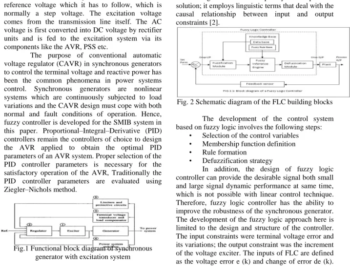
The fuzzy logic use has received a lot of attention in the recent years because of its usefulness in reducing the model's complexity in the problem solution; it employs linguistic terms that deal with the causal relationship between input and output constraints [2].
Fig. 2 Schematic diagram of the FLC building blocks The development of the control system based on fuzzy logic involves the following steps:
• Selection of the control variables • Membership function definition • Rule formation
• Defuzzification strategy
In addition, the design of fuzzy logic controller can provide the desirable signal both small and large signal dynamic performance at same time, which is not possible with linear control technique. Therefore, fuzzy logic controller has the ability to improve the robustness of the synchronous generator. The development of the fuzzy logic approach here is limited to the design and structure of the controller. The input constraints were terminal voltage error and its variations; the output constraint was the increment of the voltage exciter. The inputs of FLC are defined as the voltage error e (k) and change of error de (k).
The fuzzy controller ran with the input and output normalized universe [-1, 1] [5].
IV.
POWER SYSTEM
STABILIZERS
Power system stabilizer (PSS) controller design, methods of combining the PSS with the excitation controller (AVR), investigation of many different input signals and the vast field of tuning methodologies are all part of the PSS topic.
Control Action and Controller Design
The action of a PSS is to extend the angular stability limits of a power system by providing supplemental damping to the oscillation of synchronous machine rotors through the generator excitation. This damping is provided by an electric torque applied to the rotor that is in phase with the speed variation. Once the oscillations are damped, the thermal limit of the tie-lines in the system may then be approached. This supplementary control is very beneficial during line outages and large power transfers [3]. However, power system instabilities can arise in certain circumstances due to negative damping effects of the PSS on the rotor. The reason for this is that PSSs are tuned around a steady-state operating point; their damping effect is only valid for small excursions around this operating point. During severe disturbances, a PSS may actually cause the generator under its control to lose synchronism in an attempt to control its excitation field
Figure3: Lead-Lag power system stabilizer A “lead-lag” PSS structure is shown in Figure 3. The output signal of any PSS is a voltage signal, noted here as VPSS(s), and added as an input signal to the AVR/exciter. For the structure shown in Figure.3, this is given by
VPSS(s) =sKsTw/ (1+sTw). (1+sT1)/ (1+sT2). (1+sT3)/ (1+sT4). Input(s)………… (4.1)
This particular controller structure contains a washout block, sTW/ (1+sTW), used to reduce the over-response of the damping during severe events. Since the PSS must produce a component of electrical torque in phase with the speed deviation, phase lead blocks circuits are used to compensate for the lag (hence, “lead-lag’) between the PSS output and the control action, the electrical torque. The number of lead-lag blocks needed depends on the particular system and the tuning of the PSS. The PSS gain KS is an important factor as the damping
provided by the PSS increases in proportion to an increase in the gain up to a certain critical gain value, after which the damping begins to decrease. All of the variables of the PSS must be determined for each type of Generator separately because of the dependence on the machine parameters. The power system dynamics also influence the PSS values. The determination of these values is performed by many different types of tuning methodologies, as will be shown in Section 4.3. Other controller designs do exist, such as the “desensitized 4-loop” integrated AVR/PSS controller used by Electricité de France [26] and a recently investigated proportional-integral derivative (PID) PSS design [27]. Differences in these two designs lie in their respective tuning approaches for the AVR/PSS ensemble; however, the performance of both structures is similar to those using the lead-lag structure. Fuzzy logic is based on data sets which have non-crisp boundaries. The membership functions map each element of the fuzzy set to a membership grade. Also fuzzy sets are characterized by several linguistic variables. Each linguistic variable has its unique membership function which maps the data accordingly [20]. Fuzzy rules are also provided along with to decide the output of the fuzzy logic based system. A problem associated with this is the parameters associated with the membership function and the fuzzy rule; which broadly depends upon the experience and expertise of the designer [23]. Other controller designs do exist, such as the “desensitized 4-loop” integrated AVR/PSS controller used by Electricity de France [3] and a recently investigated proportional-integral derivative (PID) PSS design [4]. Differences in these two designs lie in their respective tuning approaches for the AVR/PSS ensemble; however, the performance of both structures is similar to those using the lead-lag structure.
DESIGN CONSIDERATIONS:
Although the main objective of PSS is to damp out oscillations it can have strong effect on power system transient stability. As PSS damps oscillations by regulating generator field voltage it results in swing of VAR output [1]. So the PSS gain is chosen carefully so that the resultant gain margin of Volt/VAR swing should be acceptable. To reduce this swing the time constant of the „Wash-Out Filter can be adjusted to allow the frequency shaping of the input signal [5]. Again a control enhancement may be needed during the loading/un-loading or loss of generation when large fluctuations in the frequency and speed may act through the PSS and drive the system towards instability. Modified limit logic will allow these limits to be minimized while ensuring the damping action of PSS for all other system events.
Another aspect of PSS which needs attention is possible interaction with other controls which may be part of the excitation system or external system such as HVDC, SVC, TCSC, FACTS. Apart from the low frequency oscillations the input to PSS also contains high frequency turbine generator oscillations which should be taken into account for the PSS design. So emphasis should be on the study of potential of PSS-torsional interaction and verify the conclusion before commission of PSS [5].5
PSS INPUT SIGNALS:
Till date numerous PSS designs have been suggested. Using various input parameters such as speed, electrical power, rotor frequency several PSS models have been designed. Among those some are depicted below.
SPEED AS INPUT: A power system stabilizer utilizing shaft speed as an input must compensate for the lags in the transfer function to produce a component of torque in phase with speed changes so as to increase damping of the rotor oscillations. POWER AS INPUT: The use of accelerating power as an input signal to the power system stabilizer has received considerable attention due to its low level torsional interaction. By utilizing heavily filtered speed signal the effects of mechanical power changes can be minimized. The power as input is mostly suitable for closed loop characteristic of electrical power feedback.
FREQUENCY AS INPUT:The sensitivity of the frequency signal to the rotor input increases in comparison to speed as input as the external transmission system becomes weaker which tend to offset the reduction in gain from stabilizer output to electrical torque, that is apparent from the input signal sensitivity factor concept.
V.
IMPLEMENTATION
The fuzzy control systems are rule-based systems in which a set of fuzzy rules represent a control decision mechanism to adjust the effects of certain system stimuli. With an effective rule base, the fuzzy control systems can replace a skilled human operator [4]. The fuzzy logic controller provides an
algorithm which can convert the linguistic control strategy based on expert knowledge into an automatic control strategy.
The fuzzy logic controller (FLC) design consists of the following steps.
A. Selection of the Control Variables
In this work, the input variables are speed deviation and the power acceleration. The output variable is control signal to excitation input of synchronous generator.
Fig.4 Fuzzy logic controller with two inputs B. Membership function definition
Input and output membership function need to be set up. In this work, eleven types of membership functions are considered for input and output variable. The input1 and input2 are speed change (ω) and power acceleration (P). The membership function for all of parameter mentioned before is set to triangular-shaped membership function (Trimf). The range of membership function is set between -1 to 1.
Each of the input and output fuzzy variables is assigned eleven linguistic fuzzy subsets varying from negative very large (NV) to positive very large (PV). Each subset is associated with a triangular membership function to form a set of eleven membership functions for each fuzzy variable.
The linguistic variables NV, NL, NB, NM, NS, ZR, PS, PM, PB, Pl, PV stands for negative very large, negative large, negative big, negative medium, negative small, zero, positive small, positive medium, positive big, positive large, and positive very large.
∆ω ∆р NV NL NB NM NS ZR PS PM PB PL PV NV NV NV NL NB NB NM NM NS NS ZR ZR NL NV NL NL NB NB NM NM NS NS ZR ZR NB NL NL NB NB NM NM NS NS ZR ZR PS NM NL NB NB NM NM NS NS ZR ZR PS PS NS NB NB NM NM NS NS ZR ZR PS PS PM
ZR NB NM NM NS NS ZR ZR PS PS PM PM PS NM NM NS NS ZR ZR PS PS PM PM PB PM NM NS NS ZR ZR PS PS PM PM PB PB PB NS NS ZR ZR PS PS PM PM PB PB PL PL NS ZR ZR PS PS PM PM PB PB PL PL PV ZR ZR PS PS PM PM PB PB PL PL PV The rules for fuzzy control will be 121 rules and is
shown in table-1
Fig.5 Membership Function of input 1
Fig.6 Membership Function of input 2
Fig.7 Membership Function of output C. Rule formation
The rule actually shows the habit of the controller when it sense the changes of the input. It works like human brains, when problem occurred;
brain might find the way out from the problems or constraints. The solutions for the problem based on human experiences. If human involved in the similar problem before, then the brain will solve the problem quickly. This concept similar with the Fuzzy Controller rules. It will make a decision based on its rules.
The fig.8 shows the rules for this fuzzy work
Fig.8 Rule Editor
Each of the 121 control rules represents the desired controller response to a particular situation. D. Defuzzification strategy
Defuzzification is a process of converting the FLC inferred control actions from fuzzy vales to crisp values. This process depends on the output fuzzy set, which is generated from the fired rules. The performance of the FLC depends very much on the deffuzzification process. This is because the overall performance of the system under control is determined by the controlling signal (the defuzzified output of the FLC). This is implemented using following FIS (fuzzy Inference System) properties: And Method: Min, Or Method: Max, Implication: Min
Aggregation: Max, Defuzzification: Centroid
VI.
SIMULATION RESULTS
After completed setting for fuzzy logic controller, simulation can be done easily. The important thing in this step knows the type of the components or devices that will be used. By choosing appropriate components, the simulation for the system can be made. Figure 9 shows the generator with hydraulic turbine governor and excitation system and FLPSS.
Fig.9 Single Generator with HTG, excitation system and FLPSS
For every condition, active power of the machine is chosen as a comparison. This is because for every system the value of the power had been set up at the start simulation. The comparison had been done after the simulation of the system subjected to three phase to ground fault. The result also shows that the system with Fuzzy Logic Power System Stabilizer more stable. Fig.9 shows the output active power for system with three phases to ground fault for different cases. The sample of time for the system responses was in five seconds. This is acceptable length of time because of at this time; most of the system had achieved desired active power that 1.0 Pu. The comparison had been made by looking at the oscillation and also the time taken by each stabilizer to achieve desired value and also stable after system subjected to disturbances.
Fig.10 Output active power for different cases
VII.
CONCLUSION
The stable systems mean the ability of the system to damp the power oscillatory to a new steady state in finite time. The addition of power system stabilizer is to damp the oscillation of power system. This is shown by the result of the simulation. By comparing the output active power for different cases
in fig.9 we conclude that the system operated with Fuzzy Logic Power System Stabilizer achieve the desired value of active power at 1.33 seconds compared to Conventional Power System Stabilizer at 1.46 seconds. This meant Fuzzy Logic Power System Stabilizer achieve the settling time by quicker than Conventional Power System Stabilizer.
REFERENCES
[1]. Abdullah Mohammed.Kh, “Design of anti windup AVR for synchronous generator Using MATLAB simulation.’’ Elec.engdept/college of engg of mosul,al-Rafian engg,vol.17.no3,june 2009.
[2]. Hiyama T., Oniki S., Nagashima H. Evaluation of advanced fuzzy logic PSS on analog network simulator and actual installation on hydro generators, IEEE Trans. on Energy Conversion, Vol. 11, No. 1, pp. 125-131, 1996.
[3]. K.Ogata, Modern Control Systems, 5th edition, Prentice Hall Publications-2002. [4]. Kundur.P, “Power System Stability and
Control”, New York: McGraw-Hill, 1994. [5]. Ziegler-Nichols (Z-N) Based PID Plus
Fuzzy Logic Control (FLC) For Speed Control of A Direct Field-Oriented Induction Motor (DFOIM). Int. Journal of Engineering Research and Applications,Vol. 3, Issue 6, Nov-Dec 2013, pp.755-762 [6]. A. Ghosh , G. Ledwich, O.P. Malik and G.S.
Hope, ”Power System Stabilizer Based on Adaptive Control techniques”, IEEE Transaction on Power Apparatus and System, Vol. PAS- 103, No.8, August 1984. [7]. D.Sumina,“Fuzzy logic excitation control of
synchronous generator”, Master thesis, Faculty of electrical engineering and computing, 2005.
BIOGRAPHIES
Srinivas Singirikonda, Asst.Professor
Received M.Tech degree in Control Systems in Dept. of Electrical and Electronics Engineering, JNTU Hyderabad. He is currently working as Asst. Professor in EEE Department of Siddhartha Institute of Engineering& Technology, Hyderabad; His is doing currently research in Fuzzy logic controllers.
G. Sathish Goud, Asst. Professor
He is currently working as Asst. Professor in EEE Department of Siddhartha Institute of Engineering& Technology, Hyderabad; His is doing currently research in Fuzzy logic controllers and electrical power systems.
M. Harika Reddy, Asst. Professor. Received M.Tech degree in power electronics in Dept. of Electrical and Electronics Engineering, JNTU Hyderabad. She is currently working as Asst. Professor in EEE Department of Sri Indu college of Engineering& Technology, Hyderabad; She is doing currently research in Fuzzy logic controllers and power electronics