ISSN Online: 2169-9631 ISSN Print: 2169-9623
DOI: 10.4236/ojer.2018.72006 May 30, 2018 88 Open Journal of Earthquake Research
Codal Requirements Using Capacity Design
Philosophy, and Their Applications in the
Design of Steel Structures in Seismic Zones
Muhammad Tayyab Naqash, Ayed Alluqmani
Department of Civil Engineering, Islamic University in Madinah, Madina Almunaworah, KSA
Abstract
The use of steel structures in the developing countries is limited in spite of its better performance in the case of seismic events due to its high ductility. Al-though steel structures behave well under seismic excitation, nevertheless the use of structural steel is limiting these days. This paper aims to address vari-ous parameters related to the capacity design approach involved in the seismic design of conventional steel structures. Few cases of the early steel structures construction such as bridges in Pakistan are briefly described. Philosophies based on the capacity design approach and the importance of conventional steel lateral load resisting systems with their global mechanisms are pro-vided. The design procedures of Eurocode 8 for Steel Moment resisting frames, Concentric cross braced frames and Eccentric braced frames are given and illustrated. It is believed that the paper will contribute and will be helpful for the designers, researchers and academicians involve in the study of lateral load resisting systems for incorporating in the design process. Since synopsis tables are provided, therefore this will allow a clear under-standing of the capacity design approach for different lateral load resisting systems.
Keywords
Moment Resisting Frames, Concentric Cross Braced Frames, Eccentric Braced Frames, Behaviour Factor, Eurocode 8, Seismic Code in Pakistan
1. Introduction
The philosophies of seismic design codes rely on the inherent capability of structures to undergo inelastic deformation. Since steel is strong, light weight, ductile and tough material hence believed to be capable of dissipating extensive
How to cite this paper: Naqash, M.T. and Alluqmani, A. (2018) Codal Requirements Using Capacity Design Philosophy, and Their Applications in the Design of Steel Structures in Seismic Zones. Open Journal of Earthquake Research, 7, 88-107. https://doi.org/10.4236/ojer.2018.72006
Received: April 16, 2018 Accepted: May 27, 2018 Published: May 30, 2018
Copyright © 2018 by authors and Scientific Research Publishing Inc. This work is licensed under the Creative Commons Attribution International License (CC BY 4.0).
DOI: 10.4236/ojer.2018.72006 89 Open Journal of Earthquake Research energy through yielding when stressed in the inelastic range, these are exactly the properties desired for seismic resistance. In fact, other construction materials rely on these basic properties of steel to assist them in attaining adequate seismic resistance. Throughout the relatively brief history, structural steel buildings have been among the best performing structural systems. Prior to January 1994 when previously unanticipated connection failures were discovered in some buildings following the Northridge earthquake (M 6.7), many engineers mistakenly re-garded such structures as nearly earthquake-proof. A year later, the Kobe earth-quake (M 6.9) caused collapse of 50 steel buildings confirming the potential vul-nerability of these structures. This experiences notwithstanding structural steel buildings if properly designed can provide outstanding earthquake performance. This paper introduces the general concepts of conventional steel structures that should be followed during analyzing and designing when dealing with earth-quake forces. The trend of design of steel structures is highly encouraging in Pa-kistan as it is a high seismic region; the October 2005 earthquake is a clear ex-ample. Nevertheless, less work has been done on the seismic design of steel structures compared to other materials such as masonry, reinforce concrete and timber etc. It is to be noted here that Building Code of Pakistan (BCP) [1] with the aid of “UBC 97” [2] is the only reference Code that is adopted in the Country and is recommended by Earthquake Reconstruction and Rehabilitation Author-ity. The seismic zones as mentioned in Table 1 defined by this Code are com-patible with the zonation map of Pakistan. The seismic zones as shown in Figure 1 assumed by BCP are mentioned in Table 1 considering five seismic zones. Since it is believed and recommended by the design community that steel struc-tures perform well during earthquake, therefore, it is of high interest to the pos-sibilities of applying more advanced design procedures in Pakistan. Seismic de-sign procedures, accurate seismic zoning, and related earthquake dede-sign Codes are the topics of high concern in Pakistan. Some major past earthquakes that hit the country with fatalities are mentioned below [3][4].
• In 1935 at 05:30—Quetta, Pakistan—M 7.5 Fatalities 30,000. • In 1945 at 11:27—Makran Coast, Pakistan—M 8.0 Fatalities 4000. • In 1974 at 12:28—Northern Pakistan—M 6.2 Fatalities 5300. • In 2005 at 10:08—Kashmir Pakistan—M 7.6 Fatalities 86,000. • In 2008 at 10:28—Pakistan—M 6.4 Fatalities 166.
• In 2011 at 01:18—Pakistan—M 7.2 Fatalities 3.
2. Steel Structures in Pakistan
DOI: 10.4236/ojer.2018.72006 90 Open Journal of Earthquake Research Table 1. Seismic zones of Pakistan.
S. No Seismic Zones Peak Ground Acceleration Hazard Level Damage Intensity Damage Effect
1 1 0.05 to 0.08 g Low Negligible Low
2 2A 0.08 to 0.16 g
Moderate Minor Medium
3 2B 0.16 to 0.24 g Moderate
4 3 0.24 to 0.32 g Large Sever High
5 4 >0.32 g Sever Collapse Huge
NOTE: Where “g” is the acceleration due to gravity. The acceleration values are for Medium hard rock (SB)
site condition with shear wave velocity (vs) of 760 m/sec.
Figure 1. Seismic zoning map of pakistan.
independence of Pakistan from the British steel Moment Resisting Frames achieve good performance under seismic events. After the 1931 Mach earth-quake some structures (see Figure 2) were designed according to the recom-mendation provided by Eng. Kumar which were tested by the 1935 Quetta earthquake and evidenced that even a modest design of steel structures saved lives in such earthquakes. These frames resisted the 1935 Quetta earthquake without significant damages [5][6].
[image:3.595.232.515.236.467.2]DOI: 10.4236/ojer.2018.72006 91 Open Journal of Earthquake Research Figure 2. Undamaged steel structures tested by 1935 Quetta earthquake.
(a) (b)
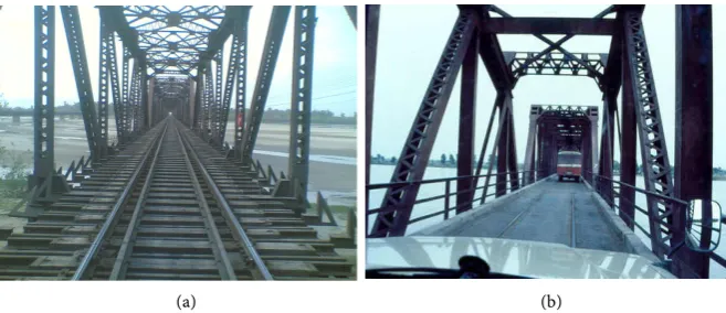
Figure 3. (a) Alexandria bridge, gujarat; (b) Old bridge over Jhelum.
single-span cantilever bridge completed in 1889. It was one of the great engi-neering feats of its time because the Indus River was too large to divert its waters to install piers therefore large beams cantilevered from the river side and was supported by the land on the other side. These cantilevers from both sides were joined in the middle by a system of trusses. Just 30 m away from this bridge the Ayub Arch stands which is an arch-pan bridge built to divert railway traffic away from the aging Lansdowne Bridge Rohri. The Attock railway bridge (Figure 4), the Alexandria Bridge in Jhelum and the Ayub arch bridge (See Figure 5) are about 50 years old whereas the Lansdowne bridge is about 100 years old located in Rohri, Sukkur. The Attock Bridge consisted of 5 spans, three are 257 ft. long and two are 312 feet long. The historical bridge (Figure 6 and Figure 7) at Ma-lakwal-Haranpur section on river Jhelum connect the three districts of Punjab, i.e. Mandi Bahauddin, Jhelum and Sargodha at a same place.
In Pakistan, almost all the railway station are ancient such as the one of La-hore (see Figure 8), constructed in British era. Due to un-availability of data on specific structure sufficient information is not available but the authors aims to enlarge such study in future to enhance the culture of steel structure in the Country [7].
[image:4.595.207.536.207.349.2]DOI: 10.4236/ojer.2018.72006 92 Open Journal of Earthquake Research Figure 4. Attock Bridge.
Figure 5. Lansdowne and ayub arch bridge.
Figure 6. Historical bridge at Malakwal-Haranpur section on river Jhelum.
Figure 7. Victoria Bridge Historical bridge at Malakwal-Haran Pur section on river Jhe-lum.
3. Parameters Used in Capacity Design Approaches
[image:5.595.207.540.431.507.2] [image:5.595.207.539.540.627.2]DOI: 10.4236/ojer.2018.72006 93 Open Journal of Earthquake Research Figure 8. Lahore railway station showing the roof trusses (courtesy unknown).
[image:6.595.208.537.270.406.2](a) (b) (c)
Figure 9. (a) Telecome tower; (b) Electric Transmission tower; (c) Overhead water tank.
(a) (b)
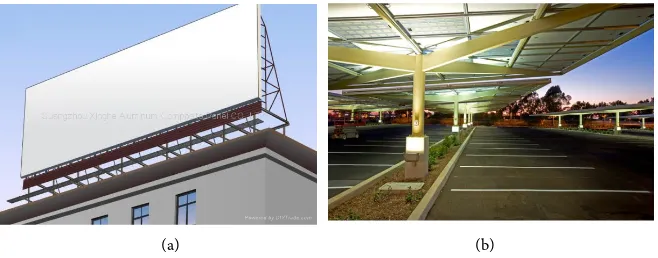
Figure 10. (left) Sign board (right) Parking shade.
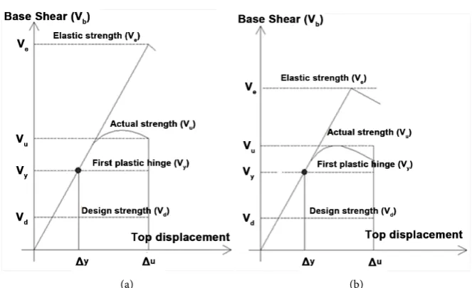
medium and long period, the “equal displacement rule” implies. Therefore the main factors affecting the structural behavior under seismic excitation can be obtained from pushover analysis using the “equal displacement rules”, as shown
in Figure 11 and explained in the following [10][11][12].
Ductility reduction factor: It is the ratio of Ve to Vy as shown in Equation (1), it can also be termed as expected behaviour factor.
, e
y
V q
V
[image:6.595.211.540.444.573.2]DOI: 10.4236/ojer.2018.72006 94 Open Journal of Earthquake Research
[image:7.595.207.539.65.267.2](a) (b)
Figure 11. Common factors used in seismic Codes (a), and equal displacement approxi-mation (b).
Redundancy factor: It is the over-strength given by the redistribution of the plastic hinges and termed as redundancy factor; it is the ratio of Vu obtained from pushover analysis to Vy defined by Equation (2). Redundancy exists when multiple elements must yield or fail before a complete collapse mechanism forms. Structures possessing low inherent redundancy are required to be stronger and more resistant to damage and therefore seismic design forces are amplified. Therefore, normally it is assumed that structures having larger global ductility exhibits high redundancy and vice versa.
u
y
V V ρ
Ω = (2)
Elastic overstrength factor: It is the allowable stress reduction factor and is given by the ratio of Vy to Vd given by Equation (3). As an ideal scenario in the design ΩE might be unity. Since the structural capacity must not be less than the design forces, ΩE is always at least 1.
y E
d
V V
Ω = (3)
Global overstrength factor: It is given by the ratio of Vu to Vd; it corresponds to the product of redundancy factor and elastic overstrength, evaluated from Eq. (4).
, y u u
E E
d y d
V V V
V V V
ρ ρ
Ω = Ω × Ω = × =
(4)
Reserve ductility: It is the ratio of Ve to Vu as given in Equation (5) as well from Equation (7) and Equation (8).
e
u
V q
V
µ
=
DOI: 10.4236/ojer.2018.72006 95 Open Journal of Earthquake Research Behaviour factor: It is given by the ratio of Ve to Vd. it is simply the product of elastic overstrength, redundancy factor and reserve ductility defined by Eq. (6).
or
y u e e u
d E d
d y u d y
V V V V
q q q
V V V V
ρ µ
∆
= Ω × Ω × = × × = =
∆
(6)
,
e d
u E
V q
q V µ
ρ
= =
Ω (7)
, e u
y
V
q q
V
µ ρ= = × Ωρ (8)
4. Lateral Load Resisting Systems
Seismic design necessitates the combinations of deformability, strength and most importantly the ductility characteristics of a structural system. Although steel structures have the capability to resist the lateral actions by means of dif-ferent Lateral Load Resisting Systems (LLRS). Nevertheless the impairing of strength with the ductility and deformability is a big challenge for the designer. Several types of earthquake resistant steel structures (some LLRS can be com-bined with the others) which depend on the selected load carrying mechanism can be conceived. These LLRSs have pros and cons on each other due to their characteristics such as high deformability (like MRFs), architectural constraints (like cross bracing that may restrict the opening) and geotechnical issues (for example concentration of forces on the footings). The most conventional types of earthquake resistant steel structures are: a) Rigid Frames, b) Concentric Braced Frames and c) Eccentric Braced Frames.
DOI: 10.4236/ojer.2018.72006 96 Open Journal of Earthquake Research Figure 12. Capacity design flowchart for steel MRF using Eurocodes process.
4.1. Rigid Frames
In this section rigid steel frames are discussed which remain elastical or in-elastical depending on the loading conditions. In the case of a low earthquake according to the performance criteria MRFs should be remain in the elastic state. On the other hand for any strong motion earthquake rigid frames might behave in elastically with the condition that it dissipates the seismic energy. Stiffness is affected if MRFs goes into the plastic state. The plastic state of rigid frames in the case of seismic event can be controlled by applying the capacity design rules [13]. The here presented Table 2 shows a synopsis for the capacity design rules for EC3-EC8 (DCH) and AISC-ASCE (SMF).
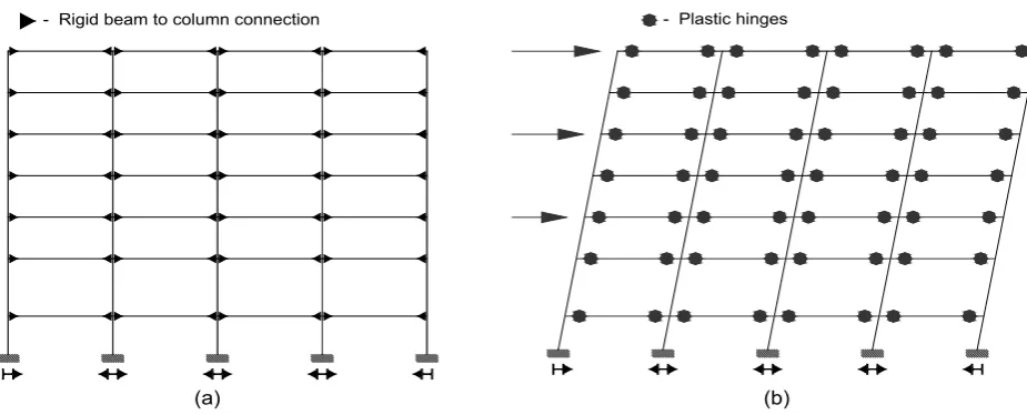
As moment resisting frames are realized by rigid connections (See Figure 13) therefore guarantees clear opening for therefore offers great flexibility for archi-tectural requirements. Generally the lateral stiffness of steel moment resisting frames is low having excessive deformability and therefore occasionally may al-low damage to non-structural elements. Nevertheless due to their high inelastic capabilities the energy dissipation in MRFs is high. If energy dissipation takes place through hysteresis loops at the ends of the beams a ductile collapse me-chanism in MRFs is achieved. In this case most convenient collapse distribution foresees by emerging plastic hinges at beam ends and at column bases. This leads to a global mechanism that maximizes the amount of dissipated energy and causes a local ductility demand lower than other collapse mechanisms such as plastic hinges at the column bases. From the capacity design perception, beams are the dissipative elements, whereas connections and columns are non-dissipative elements and must be designed for higher seismic forces to be remain in the elastic state at the level of plasticity in beams ends [20][21].
In Eurocode 8 the design elastic response spectrum is normally reduced by a behavior factor (q) that equals to 4 for DCM and 6.5 for DCH. Furthermore in order to have a global ductile behavior of the MRFs, beams should be verified in order to have sufficient resistance against lateral torsion buckling in accordance with EN 1993. Beam ends are the fuses in rigid frames and if these are designed properly they perform well. For assuring plastic hinges in the beams, Code gives some supplementary checks for the beams of MRF where demand to ca-pacity due to moment is 100%, due to shear it is 50% whereas due to axial it is only 15% as brittle failure is more related to shear and axial. Column are as-sumed to be elastic as more vulnerable to axial forces specially the compressive
Load analysis -Verical loads -Elastic spectrum(Sa) -Load combinations
Ductility [Sa/q] -DCH -DCM -DCL Preliminary design -Beams -Columns Calculate -Overstrength Capacity design checks
-Design columns -Check SCWB Check drift OK Revise design -Beams (more influential) -Columns Improve stiffness of frames Assumptions
-Material -Beams/Columns orientations
-Location Drift not
compatible with q Compatibility
q and drift limit
Check Performance Drift limit [Sa/qd]
-L1 = 0.01h -L2 = 0.0075h -L3 = 0.005h
DOI: 10.4236/ojer.2018.72006 97 Open Journal of Earthquake Research Table 2. Capacity design rules and drifts limitations.
Description EC8-DCH ASCE-SMF
Restrictions on the use of Cross
section For q higher than four only class 1 sections are permitted to be used Sections must be compact
Seismic load reduction factor q equal to 5αu/α1 R equal to 8
Energy dissipation philosophy
(significant inelastic deformation) Given by ductility class high Given by special moment resisting frames, and are anticipated to undergo
Overstrength factor Obtained from ratio of plastic moment of columns to beams Restricted to 3
Local ductility Plastic hinge rotation is restricted to 35 mrad Plastic hinge rotation is restricted to 30 mrad with inter-storey drifts to 0.04 radians
Strength checks for Beams , , ,
, , ,
1.0, 0.15, 0.5
E d E d E d
pl Rd pl Rd pl Rd
M N V
M ≤ N ≤ V ≤ Only strength checks as per AISC/LRFD are required
Ratio q =?
Ω 8 2.673
R= = Ω
Strong column weak beam (SCWB)
philosophy
∑
MRc≥1.3∑
MRb*
* 1.0
pc
bc
M M ≥
∑
∑
, Columns should have sufficientflexural strength Non-dissipative members
such as columns
, 1.1 ,
Ed Ed G ov Ed E
N =N + γ ΩN MEd=MEd G, +1.1γovΩMEd E,
, 1.1 ,
Ed Ed G ov Ed E
V =V + γ ΩV
Verification of strength with loads computed from special load combinations having Ωo
[image:10.595.65.528.377.564.2]Connections full strength full strength
Figure 13. Moment Resisting Frames: general scheme (a) and global collapse mechanism (b).
ones, therefore the actual seismic forces are increased by overstrength factor. Columns shall be verified in compression considering the most unfavorable combination of the axial force and bending moments. More generally, global ductility is achieved by the implementation of Strong Column Weak Beam “SCWB” philosophy. In this context, Eurocode 8 suggests the condition shown in Equation (9) must be fulfilled at all seismic beam-to-column joints:
1.3
Rc Rb
M ≥ M
∑
∑
(9)The factor 1.3 takes into account the strain hardening and the material
over-(a)
- Plastic hinges
(b)
DOI: 10.4236/ojer.2018.72006 98 Open Journal of Earthquake Research strength which is obtained generally by the multiplication of 1.1 with γov and as a general rule is considered as 1.3. Generally this check is often satisfied at the joint when capacity design is employed in the design.
4.2. Eccentric Braced Frames (EBFs)
Eccentrically braced frames as shown in Figure 15 are a sort of “compromise” between moment resisting frames and concentrically braced frames. They are conceived for combining the advantages of MRFs in terms of ductility and energy dissipation capacity, with those of CBFs in terms of lateral stiffness. With regard to the architectural flexibility the EBFs solution shows interme-diate peculiarities. Therefore the most attractive feature of EBFs for seismic-resistant design is their high stiffness combined with excellent ductility and ener-gy-dissipation capacity. The braces in EBFs deliver the high elastic stiffness cha-racteristic of CBFs, permitting Code drift requirements to be met economically. Additionally under severe earthquakes properly designed and detailed EBFs provide the ductility and energy dissipation capacity characteristic of MRFs [22]. The basic idea is to endow moment resisting frames with appropriate braced members and thus reduce the lateral deformability of the frame. At the same time, since at least one end of the braces is connected to the beams, a part of these, usually called “link”, is devoted to the dissipation of the input energy by yielding in shear and/or in flexure as shown by Figure 14.
[image:11.595.60.536.516.708.2]In this way the stiffness and ductility properties can be in principle adequately calibrated, so leading towards optimal structural solutions. The performances of the structure are strongly dependent on the behavior of the links, require partic-ular care in the design phase [23]. Eurocode 8 gives simple rules for the design of EBFs where the seismic energy dissipation is taken by vertical or horizontal seismic links. The behavior of link is related to their dimensions and internal forces and therefore three different types of links are defined namely, the short
Figure 14. Eccentrically Braced Frames: general scheme (a) and collapse mechanism (b).
(a) (b)
DOI: 10.4236/ojer.2018.72006 99 Open Journal of Earthquake Research link (dissipation is guaranteed by yielding in shear), the long link (link dissipate energy by yielding in flexure, see Figure 15(b)) and the intermediate link (where plastic mechanisms is a combination of bending and shear). Figure 15(a) and
Figure 15(b) show the Energy W dissipated in plastic mechanisms in shear and
in bending. The plastic mechanism achieved in seismic links depends on their length. Short links yield essentially in shear, the energy dissipated in the plastic mechanism is given by Equation (10):
,
v p link p
W =V ×θ ×e (10)
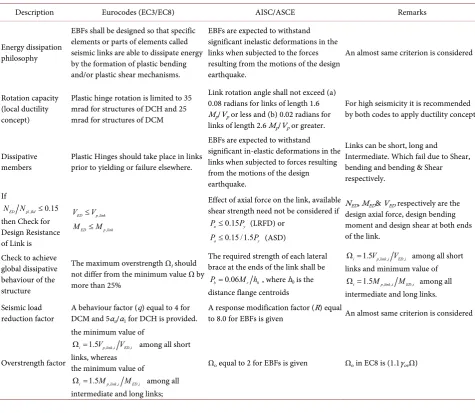
Table 3 shows the provisions for Eccentric Braced Frames according to
Eu-rocodes (EC3/EC8) and AISC/ASCE.
The limit between long and short links corresponds to the situation in which yielding could equally take place in shear or bending, therefore Equation (11) explains the case.
,
, ,
,
2 2 p link
v M p link p p link p
p link
M
W W V e M e
V
θ θ
= ⇒ × × = × ⇒ = ×
(11)
For values of e around this limit, significant bending moments and shear forces exist simultaneously and their interaction has to be considered. In Euro-code 8, the value of e for considering a plastic mechanism in shear (short links) is given by Equation (12).
, ,
1.6 p link s
p link
M e e
V
< = ×
(12)
The value of e for considering only a plastic mechanism in bending (long links) is calculated using Equation (13).
,
,
3 p link L
p link
M e e
V
< = ×
(13)
[image:12.595.132.467.588.706.2]Between these two values es and eL, links are said to be “intermediate” and the interaction between shear and bending has to be considered. If the typology of the structure is such that the shear and bending moment diagrams are not sym-metrical, only one plastic hinge will form if the link is long, therefore Equation (14) takes place.
DOI: 10.4236/ojer.2018.72006 100 Open Journal of Earthquake Research Table 3. Provisions for eccentric braced frames.
Description Eurocodes (EC3/EC8) AISC/ASCE Remarks
Energy dissipation philosophy
EBFs shall be designed so that specific elements or parts of elements called seismic links are able to dissipate energy by the formation of plastic bending and/or plastic shear mechanisms.
EBFs are expected to withstand significant inelastic deformations in the links when subjected to the forces resulting from the motions of the design earthquake.
An almost same criterion is considered
Rotation capacity (local ductility concept)
Plastic hinge rotation is limited to 35 mrad for structures of DCH and 25 mrad for structures of DCM
Link rotation angle shall not exceed (a) 0.08 radians for links of length 1.6 Mp/Vp or less and (b) 0.02 radians for links of length 2.6 Mp/Vp or greater.
For high seismicity it is recommended by both codes to apply ductility concept
Dissipative
members Plastic Hinges should take place in links prior to yielding or failure elsewhere.
EBFs are expected to withstand significant in-elastic deformations in the links when subjected to forces resulting from the motions of the design earthquake.
Links can be short, long and Intermediate. Which fail due to Shear, bending and bending & Shear respectively.
If
, 0.15
ED pl Rd
N N ≤
then Check for Design Resistance of Link is
,
ED p link
V ≤V
,
ED p link
M ≤M
Effect of axial force on the link, available shear strength need not be considered if
0.15
u y
P ≤ P (LRFD) or
0.15 /1.5
a y
P ≤ P (ASD)
NED, MED& VED respectively are the design axial force, design bending moment and design shear at both ends of the link.
Check to achieve global dissipative behaviour of the structure
The maximum overstrength Ωi should not differ from the minimum value Ω by more than 25%
The required strength of each lateral brace at the ends of the link shall be
0
0.06
b r
P = M h , where h0 is the distance flange centroids
, , ,
1.5
i Vp link i VED i
Ω = among all short
links and minimum value of
, , ,
1.5
i Mp link i MED i
Ω = among all
intermediate and long links. Seismic load
reduction factor
A behaviour factor (q) equal to 4 for DCM and 5αu/α1 for DCH is provided.
A response modification factor (R) equal
to 8.0 for EBFs is given An almost same criterion is considered
Overstrength factor
the minimum value of
, , ,
1.5 i Vp link i VED i
Ω = among all short
links, whereas the minimum value of
, , ,
1.5
i Mp link i MED i
Ω = among all
intermediate and long links;
Ωo equal to 2 for EBFs is given Ωo in EC8 is (1.1γovΩ)
,
M p link p
W =M ×θ (14)
In this case, the limiting length between long and short links corresponds to Equation (15). , , p link p link M e V ⇒ =
(15)
The following rules are allowed by Eurocode 8:
1) The reduction of the elastic design spectrum through a behavior factor (q) equals to 4 for DCM and 6.5 for DCH; 2) The web of the link should not be reinforced with plate, 3) In cases, when Equation (16) holds.
,
0.15 Ed
Pl Rd
N
N ≤ (16)
In cases, when Equation (17) is satisfied.
,
0.15 Ed
Pl Rd
N
DOI: 10.4236/ojer.2018.72006 101 Open Journal of Earthquake Research Then plastic shear and moment should be reduced by the effect of axial forces in the bracings.
The recommended inelastic rotation limits for different link lengths without restriction on the configuration of the link are; 0.08 radians or 4.6 for Short links, 0.02 radians or 1.15˚ for Long links and for Intermediate links the value is de-termined by linear interpolation. The criteria that must be satisfied in order to form a global plastic mechanism are similar in frames with eccentric or concen-tric braces, because they correspond to the same concept. Further, there should be homogenization of the dissipative connections overstrength Ωi over the height of the building for short and long links is calculated using Equation (18) and Equation (19), respectively:
Short links: , ,
,
1.5 pl Rd i i
Ed i
V V
Ω =
(18)
Long links: , ,
,
1.5 pl Rd i i
Ed i
M M
Ω =
(19)
The minimum value of Ωishould be used in the design, further the maximum value of Ωi should not differ from the minimum by more than 25%. Ωi will en-sure that yielding occurs simultaneously at several places over the height of the building, and a global mechanism is formed. The beams, columns, and connec-tions are “capacity designed” relative to the real strengths of the seismic links.
4.3. Concentric Braced Frames (CBFs)
One of the main concern of steel MRFs is their high susceptibility to large lateral displacements (lateral stiffness) during severe earthquakes, therefore needs spe-cial attention while designing. In order to limit interstorey drift, the issues due to geometric nonlinearities and brittle fracture of beam-to-column connections are mitigated and therefore excessive damage to non-structural elements is avoided. Therefore as an alternative, to many practical and economic issues involved, en-gineers are increasingly turning to the use of concentrically braced steel frames as a structure’s lateral load resisting system. Steel concentrically braced frames are assumed and recommended to be strong, stiff and ductile. The quality of the seismic response of these frames is determined by the performance of the brace. For achieving a good performance in cross bracing system the brace must be-have as a structural fuse thus should fail prior to any other component of the frame. This is important because although the frame may sustain significant damage during an earthquake, it is expected to remain stable and the building must be capable of resisting gravity loads and withstanding aftershocks without collapse.
DOI: 10.4236/ojer.2018.72006 102 Open Journal of Earthquake Research compression. From an architectural point of view, the meshes of the frame which are occupied by the braces cannot be used for openings, with consequent functional flexibility reduction. The initial lateral stiffness of CBFs is generally high, due to the axial stiffness of the braces. On the other hand, the capacity of dissipating the input seismic energy is quite poor, it being based on the plastici-zation of braces in tension. The effectiveness of this dissipation mechanism is reduced cycle by cycle, due to the degradation caused by the repeated buckling undergone when braces are subjected to compression (see Figure 16). From the capacity design point of view, the dissipative elements are the braces, whereas the connections, the beams and the columns must be over-resistant, behaving in the elastic field up to the failure of the braces [24].
A similar approach like the one for MRFs is defined by Eurocode 8 for con-centric braced frames. In this case it is aimed to obtain a ductile behavior by imposing that the yielding of diagonal members occurs before premature failure of beams, columns and connections (capacity design approach) [23][25][26]. In order to obtain such strength hierarchy among the structural members, Euro-code 8 [13] provides a simplified design procedure. This approach begins from a linear analysis of CBF structure under reduced seismic loads. With reference to frames with cross bracing (X-CBF) the simplified procedure involves the fol-lowing assumptions, limitations and checks: a) the reduction of the elastic design spectrum through a behavior factor (q) equals to 4 for both DCM and DCH (See
Figure 17); b) the use of a scheme with tension-only diagonals for the evaluation
of the design axial forces in the braced frames members (Figure 18); c) a maxi-mum allowable value for the non-dimensional slenderness λ of diagonals is given as λ ≤2.0.
2.0
λ ≤ is used to ensure satisfactory behavior under cyclic loading, where λ is defined as the square root of the ratio between the plastic resistance
,
pl Rd
[image:15.595.57.537.505.710.2]N and the Eulerian buckling load Ncr of the diagonal.
Figure 16. Concentrically Braced Frames: (a) general scheme; (b) collapse Mechanism.
(a) (b)
DOI: 10.4236/ojer.2018.72006 103 Open Journal of Earthquake Research Figure 17. Reduction of the elastic spectrum
(Eurocode 8 spectrum [13]).
Figure 18. Axial forces in diagonal and column: Tension only model.
d) A minimum allowable value for the non-dimensional slenderness λ of diagonals is given by λ>1.3.
e) In the case of cross bracing configurations (X-CBFs), devoted to avoid overloading of columns in the pre-buckling stage of compressed diagonal, i.e. when the actual structural scheme is the Tension/Compression one; where Ωiis the diagonal overstrength coefficient for the ith diagonal members of the consi-dered braced frame, defined as the axial strength capacity to demand ratio, given by Equation (20).
, ,
,
pl Rd i i
Ed i
N N
Ω =
(20)
A maximum allowable value for the difference between the maximum (Ωmax) and the minimum (Ωmin) values of the diagonal overstrength coefficients Ωi, ac-cording to Equation (21).
max
min
1.25
Ω ≤
Ω (21)
Equation (21) is devoted to obtain a uniform distribution of plastic demand along the building height, thus reducing the potential for damage concentration and eventual soft-storey mechanisms;
T [sec] a- Peak ground accelaration
a ad
1
1 2µ−1
1
µ Elasitc spectrum
In elasitc spectrum
[image:16.595.202.391.270.400.2]DOI: 10.4236/ojer.2018.72006 104 Open Journal of Earthquake Research f) The amplification of design axial forces in beam and columns (non-dissipative elements) through the system overstrength factor Ω.
5. Conclusion
The paper has dealt initially with the importance of seismic codes in general and particularly in Pakistan. From past earthquakes for example Quetta 1935, it is revealed that steel structures performed well within the limited use of steel frame structures; nevertheless their trend is still not so common in Pakistan. Useful and important steel structures have been constructed before the independence of Pakistan as mentioned in this paper. Furthermore, the use of most advance code such as Eurocode 8 is convenient to be used in the country as the defined spec-trum of the code is based on the seismic zonation which is presently available for all the regions of the country. Common parameters that are normally adopted by seismic codes are given and the importance of over-strength factor especially the elastic one that was highlighted gives a clear understanding for the designer in-volved in the seismic design of structures. In addition, conventional seismic load resisting systems were illustrated and their design criteria according to Eurocode 8 were provided with synoptic tables for the counterpart US code. The proce-dure of Eurocode 8 is explained through the use of capacity design approach in which it is evident that the calculation of overstrength required some steps and iterations whereas in the US codes this factor is generally fixed for all the lateral load resisting systems. In addition, the behavior factor in Eurocode is less com-pared to the suggested value of response modification factor in the US codes. Furthermore, it is to be underline that the capacity design rule of Eurocode 8 requires some iteration as calculation of overstrength factor is involved and this becomes more complex when the deformability needs to be satisfied. It is be-lieved and concluded that the lateral load resisting systems that dissipate more seismic energy are of prime importance and therefore need attention to be in-corporated in the plastic design.
References
[1] Building Code of Pakistan (BCP) (2007) Building Code of Pakistan (Seismic Provi-sions-2007). In: Ministry of Housing and Works, Ed., Pakistan Engineering Coun-cil, Islamabad.
[2] UBC-1997 (1997) International Conference of Building Officials. ed. Whittier, California.
[3] Naqash, M.T. (2012) Optimum Design of Steel Moment Resisting Frames Using Eurocode 8. Doctorate PhD Thesis, Department of Engineering and Geology (Ph.D. Thesis), University of Chiete and Pescara, Pescara.
[4] Naqash, M.T. (2014) Study on the Fundamental Period of Vibration of Steel Mo-ment Resisting Frames. International Journal of Advanced Structures and Geotech-nical Engineering, 3, 01-06.
[5] Kumar, S.L. (1933) Theory of Earthquake Resisting Design with a Note on Earth-quake Resisting Construction in Baluchistan. Punjab Enginering Congress.
DOI: 10.4236/ojer.2018.72006 105 Open Journal of Earthquake Research Adequate Soil Conditions Using Seismic Code Provisions. Open Journal of Civil Engineering,8, 1-12. https://doi.org/10.4236/ojce.2018.82008
[7] Alvi, P.M. (2011) The Bridges of Pakistan.
http://pakistaniat.com/2011/03/11/pakistan-bridges/
[8] Miranda, E. and Bertero, V.V. (1994) Evaluation of Strength Reduction Factors for Earthquake-Resistant Design. Earthquake Spectra, 10, 357-357.
https://doi.org/10.1193/1.1585778
[9] Fajfar, P. (2000) A Nonlinear Analysis Method for Performance-Based Seismic De-sign. Earthquake Spectra, 16, 573-592. https://doi.org/10.1193/1.1586128
[10] SEAOC Seismology Committee (2008) A Brief Guide to Seismic Design Factors. STRUCTURE.
http://www.structuremag.org/Archives/2008-9/C-GuestCol-SeismicDesign-SEAOC
-Sept08.pdf
[11] Naqash, M.T. (2017) Codal Comparisons for the Seismic Resistance of Steel Mo-ment Resisting Frames (MRF). Part A: Codes Approach. International Journal of Construction Engineering and Management, 6, 254-263.
[12] Naqash, M.T. (2017) Codal Comparisons for the Seismic Resistance of Steel Mo-ment Resisting Frames (MRFs). Part B: Design Approach. International Journal of Construction Engineering and Management,6, 264-272.
[13] EN-1998-1 (2005) Eurocode 8, Design of Structures for Earthquake Resistance, Part 1: General Rules, Seismic Actions and Rules for Buildings. In:CEN, Ed., European Committee for Standardization,36 B-1050, Brussels.
[14] Gioncu, V. and Mazzolani, F.M. (2002) Ductility of Seismic Resistant Steel Struc-tures. Vol. 1, Taylor & Francis, Milton Park, Abingdon-on-Thames.
[15] Naeim, F. (1989) The Seismic Design Handbook. Springer, Berlin.
[16] Brescia, M. (2008) Rotation Capacity and over Strength of Steel Members for Seis-mic Design. UNINA.
[17] Code, I.B. (2009) International Building Code 2009 (IBC-2009). International Code Council.
[18] ASCE/SEI-7-10 (2010) Minimum Design Loads for Buildings and Other Structures. American Society of Civil Engineers, Virginia.
[19] ANSI/AISC-341-10 (2010) Seismic Provisions for Structural Steel Buildings. American Institute of Steel Construction, Chicago.
[20] Adan, S.M. and Hamburger, R.O. (2010) Steel Special Moment Frames Structure.
http://www.structuremag.org/?p=4884
[21] Bungale, S.T. (2005) Wind and Earthquake Resistant Buildings Structural Analysis and Design. Marcel Dekker, 892 p.
[22] Roeder, C.W. and Popov, E.P. (1977) Inelastic Behavior of Eccentrically Braced Steel Frames under Cyclic Loadings. NASA STI/Recon Technical Report N, Vol. 78, 20375.
[23] Brandonisio, G., et al. (2012) Seismic Design of Concentric Braced Frames. Journal of Constructional Steel Research,78, 22-37.
[24] Uriz, P. and Mahin, S.A. (2004) Seismic Performance Assessment of Concentrically Braced Steel Frames. Proceedings of the 13th World Conference on Earthquake En-gineering, Vancouver, 1-6 August 2004, 6.
Ap-DOI: 10.4236/ojer.2018.72006 106 Open Journal of Earthquake Research plied Sciences,16, 133-142.
[26] Naqash, M.T., et al.(2014) An Overview on the Seismic Design of Braced Frames. American Journal of Civil Engineering, 2, 41-47.
DOI: 10.4236/ojer.2018.72006 107 Open Journal of Earthquake Research
Nomenclature
qµ,ρ: Ductility reduction factor
Ve: Elastic base shear
Vy: Base shear obtained at the arrival of first plastic hinge Ωρ: Redundancy factor
Vu: Ultimate base shear ΩE: Elastic overstrength factor
Vd: Design base shear calculated from the prescribed Code ΩE,ρ: Global overstrength factor
qµ: Reserve ductility
R: Response modification factor q: Behaviour factor
αu: Multiplier of horizontal seismic design action at formation of global plastic mechanism
α1: Multiplier of horizontal design seismic action at formation of first plastic hinge in the system
γc: Partial factor for concrete
γRd: Model uncertainty factor on design value of resistances in the estimation of capacity design action effects, accounting for various sources of overstrength
γs: Partial factor for steel
MEd: Design bending moment from the analysis for the seismic design situa-tion
Mpl,RdA: Design value of plastic moment resistance at end A of a member Mpl,RdB: Design value of plastic moment resistance at end B of a member VEd,i, MEd,i: Design values of the shear force and of the bending moment in Link i in the seismic design situation
Vp,link,iMp,link,i: Shear and bending plastic design resistances of link i
ΣMRc and MRb: Sum of the design values of the moments of resistance framing the joint of the columns and beams respectively
NEd: Design axial force from the analysis for the seismic design situation VEd: Design shear force from the analysis for the seismic design situation NEd,E: Axial force from the analysis due to the design seismic action alone NEd,G: Axial force due to the non-seismic actions included in the combination of actions for the seismic design situation
Npl,Rd: design value of yield resistance in tension of the gross cross-section of a member
Vpl,Rd: Design value of shear resistance of a member
NRd(MEd,VEd): Design value of axial resistance of column or diagonal taking into account the interaction with the bending moment MEd and the shear VEd in the seismic situation