© 2019, IRJET | Impact Factor value: 7.211 | ISO 9001:2008 Certified Journal | Page 5570
ANALYSIS AND DESIGN OF MULTISTOREY BUILDING (G+3) BY USING
ETABS SOFTWARE
Nagaratna. S.A
1, Ranjita. N.H
2, Asif. R.S
3, Vijaykumar. K.J
4, Sudha. P.H
5, Prof. D.S. Maganur
61,2,3,4
U.G. Student, Dept of Civil Enginneering SJT Institute of Technology Ranebennur, KA, India.
5Assistant Professor, Dept of Civil Engineering STJ Institute of technology Ranebennur, KA, India.
6
Proffesor, H O D, Dept of Civil Engineering STJ Institute of Technology Ranebennur, KA, India.
---***---Abstract - Etabs stands for extended three-dimensionalanalysis of building systems. The main purpose of this software is to design multistoried building in a systematic process. The effective design and construction of an earthquake resistant structure have great importance al over the world. This project presents multi-storied residential building analyzed and designed with lateral loading effect of earthquake using ETABS. This project is designed as per INDIAN CODES-IS 1893-PART 2:2002, IS 456-2000.
Every structural engineer should design a building with most efficient planning and also be economical. They should ensure that it is serviceable, habitable in healthy environmental for its occupants and have longer design period. structurally robust and aesthetically pleasing building are beginning constructed by combining the best properties of any construction material and at the same time meeting a specific requirement like type of building and its loads, soil condition, time, flexibility and economy. In the view of above, the high-rise buildings are best suited solution. This paper discusses the analysis of a commercial building (G+3 hospital building). Shear force and bending moments of beams and columns are observed and concluded that large span having more shear forces and bending moment.
1.0 INTRODUCTION
Project on structural analysis and design of multi-storey RCC building focuses on the structural analysis of multi-storey building using appropriate methods of structural analysis and software (E-TABS).
In this project we have taken an architectural plan of the building on the basis of which the analysis will be done for the whole structure. For analysing a multi-storied building, one has to consider all the possible loadings and see that the structure is safe against all possible loading conditions.
Analysis of beams & columns has been done by using E-TABS software and slabs & footings are designed using “LIMIT STATE METHOD” according to IS: 456-2000. Materials used are of M-25 concrete and Fe-415 steel.
The building is designed as a framed structure with brick infill walls. Keeping in view the requirement & utility of the building the dead load, live load & super imposed loads have
been considered for the analysis & design of the structures in accordance with the specification of IS: 456-2000 and IS:875-1987 (Part 1 & Part2).
Subsequently, the beam column layout was prepared with the help of which slabs were identified as One Way or Two-Way Slabs. The slabs were designated names in a series as S1 &S2. The slabs were designed as per the moments obtained using the Bending Moment Co-efficient as per Annex D of IS 456: 2000.
The present project deals with the analysis of a multi-storied residential building. The dead load and live loads are applied and the design for beams, columns, footing and slabs is obtained. For design calculation MS Excel has been used.
1.1 Stages in structural design
1. Drawing study
2. Load combinations
3. Analysis of structures
4. Structural design
2.0 Objectives
© 2019, IRJET | Impact Factor value: 7.211 | ISO 9001:2008 Certified Journal | Page 5571
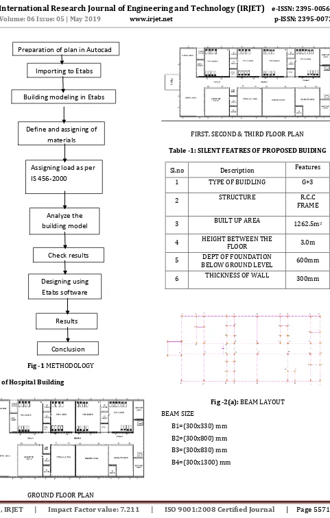
Fig -1 METHODOLOGY
3.0 Plan of Hospital Building
GROUND FLOOR PLAN
FIRST, SECOND & THIRD FLOOR PLAN
Table -1: SILENT FEATRES OF PROPOSED BUIDING
Sl.no Description Features 1 TYPE OF BUIDLING G+3
2 STRUCTURE R.C.C
FRAME
3 BUILT UP AREA 1262.5m2
4 HEIGHT BETWEEN THE
FLOOR 3.0m
5 DEPT OF FOUNDATION
BELOW GROUND LEVEL 600mm
6 THICKNESS OF WALL 300mm
Fig -2(a): BEAM LAYOUT BEAM SIZE
B1=(300x330) mm B2=(300x800) mm B3=(300x830) mm B4=(300x1300) mm
Preparation of plan in Autocad
Importing to Etabs
Building modeling in Etabs
Define and assigning of
materials
Assigning load as per
IS 456-2000
Analyze the
building model
Check results
Designing using
Etabs software
Results
[image:2.595.314.553.280.534.2]© 2019, IRJET | Impact Factor value: 7.211 | ISO 9001:2008 Certified Journal | Page 5572
Fig -2(b): COLUMN LAYOUTCOLUMN SIZE
C1=(230x300) mm C2=(450x450) mm C3=(450x600) mm C4=(600x600) mm
4.0 Analysis Methods
Etab is the primer FEM analysis and design tool for any type of project including towers, culverts, plants, bridges, stadium and marine structures. With an array of advanced analysis capabilities including linear static, response spectra, time history, cable and push over and non-linear analysis, Etab provides good compatibility with a scalable solution that will meet the demands of project every time .
5.0 Steps in Modelling
Step - 1: Initial setup of Standard Codes and Country codes.
Display units: KN-m.
Step - 2: Creation of Grid points & Generation of structure.
File → New model → Custom Grid Spacing → Edit Gird
After getting opened with ETABS we select a new model and a window appears where we had entered the grid dimensions and storey dimensions of our building.
Step - 3: Defining of Material property.
Define → Material Properties → Add New Material
Here we had first defined the material property by selecting define menu material properties. We add new material for our structural components (beams, columns, slabs) by giving the specified details in defining.
Step –4: Define Frame Sections.
Define → Frame Sections → Add Rectangular Section
After defining the property we define section size by selecting frame sections & added the required section for beams, columns etc.
Step - 5: Slab Details
Define → Wall/Slab Section → Add New Slab
We have to define the slab properties after defining frame sections.
Step - 6: Assigning of Property
After defining the property we draw the structural components using command menu. After defining the columns and beams, the columns and beams are placed on the grid lines, using various “line object” options under the command “Draw”.
Step - 7: Defining of loads
Define → Static Load Cases → Add New Load
In ETABS all the load considerations are first defined and then assigned. The loads in ETABS are defined as using static load cases.
Step - 8: Assigning of Supports
Select Plan Level →Base →Select all columns Assign →Joint Points →Restraints →Fixed Support By keeping the selection at the base of the structure and selecting all the columns we assigned supports by going to assign menu joint\frame Restraints (supports) fixed.
Step - 9: Assigning Loads Slab loads
Select slabs → Assign →Shell area loads →Uniform
6.0 ANALUSIS RESULTS
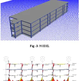
Fig -3: MODEL
[image:3.595.306.563.451.711.2]© 2019, IRJET | Impact Factor value: 7.211 | ISO 9001:2008 Certified Journal | Page 5573
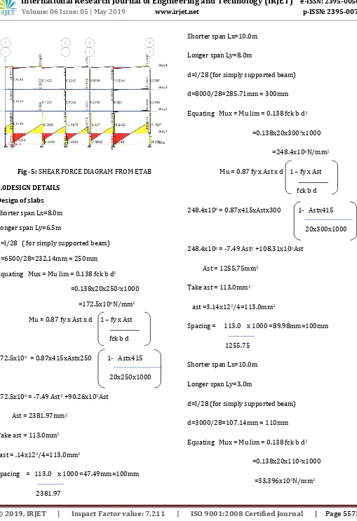
Fig -5: SHEAR FORCE DIAGRAM FROM ETAB7.0DESIGN DETAILS Design of slabs
Shorter span Lx=8.0m
Longer span Ly=6.5m
d=l/28 ( for simply supported beam)
d=6500/28=232.14mm ≈ 250mm
Equating Mux = Mu lim = 0.138 fck b d2
=0.138x20x2502x1000
=172.5x10⁶N/mm2
Mu = 0.87 fy x Ast x d 1 – fy x Ast
fck b d
172.5x106 = 0.87x415xAstx250 1- Astx415
20x250x1000
172.5x106 = -7.49 Ast2 +90.26x10³Ast
Ast = 2381.97mm2
Take ast = 113.0mm2
ast = .14x122/4=113.0mm2
Spacing = 113.0 x 1000 =47.49mm≈100mm
2381.97
Shorter span Lx=10.0m
Longer span Ly=8.0m
d=l/28 (for simply supported beam)
d=8000/28=285.71mm ≈ 300mm
Equating Mux = Mu lim = 0.138 fck b d2
=0.138x20x3002x1000
=248.4x10⁶N/mm2
Mu = 0.87 fy x Ast x d 1 – fy x Ast
fck b d
248.4x106 = 0.87x415xAstx300 1- Astx415
20x300x1000
248.4x106 = -7.49 Ast2 +108.31x10³Ast
Ast = 1255.75mm2
Take ast = 113.0mm2
ast =3.14x122/4=113.0mm2
Spacing = 113.0 x 1000 =89.98mm≈100mm
1255.75
Shorter span Lx=10.0m
Longer span Ly=3.0m
d=l/28 (for simply supported beam)
d=3000/28=107.14mm ≈ 110mm
Equating Mux = Mu lim = 0.138 fck b d2
=0.138x20x1102x1000
© 2019, IRJET | Impact Factor value: 7.211 | ISO 9001:2008 Certified Journal | Page 5574
Mu= 0.87 fy x Ast x d 1 – fy x Astfck b d
33.396x106 = 0.87x415xAstx110 1- Astx415
20x110x1000
33.396x106 = -7.49 Ast2 +39.715x10³Ast
Ast = 2112.82mm2
Take ast = 113.0mm2
ast = 3.14x122/4=113.0mm2
Spacing = 113.0 x 1000 =53.48mm≈100mm
2112.82
Design of footing:
Column size = 300 x 600mm
Grade of Concrete = M25
Grade of steel = Fe415
SBC of soil =160kN / mm2
P = 597kN
Mxx = 19kN-m
Myy = 68kN-m
Area of Footing = P/SBC
= 597/160
= 3.73 m2.
Provide a footing of 2.4 x 2.4 m
Provide area = 4 m2
Factored soil pressure = 597/4
Qu = 149.25kN/m2
Hence the footing area is adequate since the soil pressure developed at the base is less than the factored bearing capacity of soil.
Factored Bending Moments:
Cantilever projection from the short side face of
The column = 0.5(2.4-0.23)
= 1.085 m
Cantilever projection from the long side face of
The column = 0.5(2.4-0.450)
= 0.975 m
Bending moment
@short side face of the column
= (1.5x149.25x1.0852)/2
= 131kN-m
Bending moment at long side face
of the column = (1.5x149.25x0.9752)/2
=106kN-m
Depth of footing:
(a) From BM consideration
Mu = 0.133xfckxbxd2
d = 362mm
(b) From shear stress considerations we have the critical section for one-way shear is located at a distance d from the face of the column.
Shear force per meter width is
Vu = 149.25 (1085-d)
Assuming the shear strength of τc = 0.36 N/mm2 for M-20 grade concrete with nominal percentage of reinforcement Pt = 0.25
τc = Vu /bd
0.36 = 149.25(1085-d)/1000d
dmin = 317 mm
D = 600 mm
© 2019, IRJET | Impact Factor value: 7.211 | ISO 9001:2008 Certified Journal | Page 5575
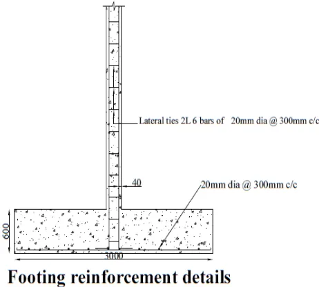
Reinforcement in footing:(a)Longer direction:
Mu =0.87xfyxAstxdx(1- fyxAst/fckxbd)
131x106 =0.87x415xAst
x550(1-415xAst/20x1000x550)
Ast = 678 mm2
Hence provide 12 mm dia bars @ 200 mm c/c.
Provide Ast = 708 mm2
(b) Shorter direction
106x106= 198577.5Ast-7.49 Ast2
Ast = 544mm2
Hence provide 12 mm dia bars @ 200 mm c/c.
Provide Ast = 565 mm2
Check for shear stress:
One Way Shear Along X-direction:
Vu = 1.5x149.25x2(1.085-(550/1000))
= 239.54kN
τv = 239.54/2400x550
= 0.1814
τc = 0.36N/mm2
Vc1 = 0.36x2400x550
= 475kN
One Way Shear Along Y-direction:
Vu =1.5x149.25x2(0.975- (550/1000))
= 190.2kN
τv = 190.2/2400x550
= 0.144
τc = 0.36N/mm2
Vc1 = 0.360x2400x550
= 475kN.
τc > τv
[image:6.595.326.557.130.338.2]Hence, safe under one-way shear.
Fig -6 Footing reinforcement details
CONCLUSIONS
1. The provided member size in the Hospital building are found safe when structure is analysed using ETABS.
2. By observing results of design data we can adopt different sizes of members at different part of the structure.
REFERENCES
1. Chandrashekar and Rajasekar (2015), “Analysis and Design of Multi Storied Building by Using ETABS Software”, International journals of scientific and research vol.4: issue.7: ISSN no. 2277-8179. 2. Balaji and Selvarasan (2016), “Design and Analysis
of multi-storied building under static and dynamic loading conditions using ETABS”, International Journal of Technical Research and Applications e-ISSN: 2320-8163, www.ijtra.com Volume 4, Issue 4, PP. 15
3. Geethu S N, Deepthi M, Abdul Nasir N A and Izzudeen K M(2016) “Comparative study on design and analysis of multi storied building by STAAD.Pro and ETABS softwares”.
4. IS 456-2000, Code of practice for plain and reinforced concrete
5. IS-875(PART-1): code for dead loads 6. IS-875(PART-2): code for imposed loads 7. IS-1893: code for seismic loads
© 2019, IRJET | Impact Factor value: 7.211 | ISO 9001:2008 Certified Journal | Page 5576
BIOGRAPHIESVIJAYKUMAR K J Student
Dept of Civil Engineering S T J I T Ranebennur
NAGARATNA S A Student
Dept of Civil Engineering S T J I T Ranebennur
ASIF R S Student
Dept of Civil Engineering S T J I T Ranebennur
RANJITA N H Student
Dept of Civil Engineering S T J I T Ranebennur
SUDHA P HADADI Professor
Dept of Civil Engineering S T J I T Ranebennur
D S MAGANUR H O D,