Master of Science Thesis
University of Twente
Formal Methods and Tools
Océ-Technologies
Automatic Verification and Analysis of Test Results
of Océ Printers
Richard Rietema
May 2009
Committee:
Preface
With this thesis three years of Computer Science and a year of final project end. Both have been periods of hard work, great fun, good talks and learning.
Many people have contributed to these periods and to my thesis in various ways. I would like to thank all of them.
First of all, I want to thank my main supervisor Mariëlle Stoelinga. She guided me during the first five months and during the last two months. In between these periods she took maternity leave. Mariëlle gave lots of interesting suggestions and provided many useful remarks.
I also want to thank my supervisor Arend Rensink. He provided many practical ideas and useful remarks on drafts of this thesis. This thesis would not look the same without his remarks.
Furthermore, I would like to thank my Océ supervisor Jac Reinders. For the valuable moments of his time, for his remarks, and the technical documents and logfiles he provided. I would like to thank all colleagues for their questions and remarks, Lou, Joost, Peter, Ton, Reinier and Sander.
Also thanks to my colleague students at Océ, Alvaro, Esmée, Eugen, Klemens and Ralph. They made the period of final project pleasant.
I would like to thank all other people who made this period to an enjoyable time. The people from „De Brug‟: family Veldhuizen, family Stephanus, and Bea. Thanks for the many meals and the good talks. And the people from Nieuwegein, for the meals and for encouraging me to write this thesis.
I would like to thank my landlady in Venlo, who used to turn the heat up before 6 am, to warm up my room.
Finally I want to thank my parents, family and friends, for their love and support, even when I only saw them once a month or less.
5
Abstract
This thesis describes the automatic verification and analysis of a printer of Océ by means of test results in the form of logfiles.
Océ is a company that develops high performance, state-of-the-art printers that produce up to 250 pages per minute. To test the complex software within these printers, all printer processes write their actions into a global logfile. When executing tests, an automatic analysis and verification of logfiles is useful, especially when these tests are automated and performed on printers under development. Currently, these logfiles are often inspected manually, which is a cumbersome and time-consuming task.
For automatic verification and analysis the logfile is transformed to a log model, which only contains log statements of functionality for tests relevant. The same (relevant) functionality is modeled in a specification. This specification consist of a composition of reference, synchronization and test-specific models representing protocols, relations between protocols, and behaviour adjusted to tests. It is defined in the formal language LOTOS. The relation between the log model and the specification is a trace membership relation, which means that a log model, if it represents correct printer behaviour, is a member of the traces formed by the specification.
This relation is implemented in a tool chain, consisting of a preprocessor, an editor, two compilers, and a Testlog verifier. The preprocessor transforms the logfile into a log model. LOTOS compilers compile the LOTOS specification, which is made in the LOTOS editor, into C code, and the Testlog verifier checks whether a relation between the log model and the compiled specification exists. Depending on the printer behaviour a verdict, true or false, is returned. In the latter case, a sequence of transitions is given which leads to the first unexpected transition in the log model.
7
Contents
ABSTRACT
5
CONTENTS
7
FIGURES
9
TABLES
11
TERMS AND ABBREVIATIONS
13
1
INTRODUCTION
15
1.1
I
NTRODUCTION TO THE PROBLEM15
1.1.1
Problem
16
1.1.2
Motivation
16
1.1.3
Solution
16
1.1.4
Results
18
1.2
B
ACKGROUND18
1.2.1
Structure
19
1.2.2
Protocols and logging
20
1.2.3
Test
22
1.2.4
Verification
23
1.3
O
UTLINE24
2
FORMAL PRELIMINARIES
25
2.1
L
ABELED TRANSITION SYSTEMS25
2.1.1
Composition of LTSs
26
2.1.2
Relation between LTSs
28
2.2
LOTOS
30
2.2.1
Basic LOTOS
30
2.2.2
Full LOTOS
32
3
METHOD
37
3.1
L
OG MODEL37
3.2
S
PECIFICATION38
3.2.1
Reference model
39
3.2.2
Synchronization model
40
3.2.3
Test-specific model
42
3.3
C
ORRECTNESS RELATION43
3.4
V
ERIFICATION44
3.4.1
On-the-fly composition of specification.
45
3.4.2
Separate verification of specification models
45
3.4.3
Composition of specification with log model
45
4
IMPLEMENTATION
47
4.1
S
PECIFICATION LANGUAGE47
4.2
T
HE TOOL CHAIN48
4.2.1
The LOTOS editor
49
4.2.2
The preprocessor
50
4.2.3
The Testlog verifier
51
4.3
A
LTERNATIVES52
4.3.1
Language
52
4.3.2
Tool
52
5
FEASIBILITY STUDY
55
5.1
P
ROTOCOLS55
5.1.1
Status protocol
55
5.1.2
Print protocol
56
5.1.3
Data protocol
57
5.2
R
ELATIONS BETWEEN PROTOCOLS58
5.2.1
Status Print synchronization model
59
5.3
T
EST SPECIFIC SITUATIONS59
5.3.1
Number of sheets test-specific model
59
5.3.2
Time test-specific model
60
5.4
C
OMPOSITION61
6
EVALUATION, CONCLUSIONS AND RECOMMENDATIONS
63
6.1
E
VALUATION63
6.1.1
Formalization of the logfile
63
6.1.2
Creation of the specification
64
6.1.3
Comparison of the formalized logfile with the specification
65
6.2
E
XPERIENCE66
6.2.1
Creation of specification
66
6.2.2
Detection of failures
67
6.2.3
Acceptance in Océ
67
6.3
C
ONCLUSIONS67
6.4
R
ECOMMENDATIONS68
9
Figures
Figure 1: Formal specification of a printer ... 17
Figure 2: Formal log model of a printer ... 17
Figure 3: Printer in environment ... 19
Figure 4: Structure of a printer ... 20
Figure 5: A part of a logfile ... 21
Figure 6: Formal verification; relation between model and specification ... 23
Figure 7: LTS of Status protocol... 26
Figure 8: LTS of Print protocol ... 27
Figure 9: LTS of parallel composition of LTSs Status and Print ... 27
Figure 10: Trace through LTS of Figure 9... 28
Figure 11: Trace inclusion ... 29
Figure 12: LOTOS specification of Status protocol ... 32
Figure 13: LOTOS specification Print protocol ... 32
Figure 14: Specification with LOTOS data type instances ... 33
Figure 15: Arbitrary LOTOS process ... 34
Figure 16: Alternative specification with value passing and constraint... 34
Figure 17: LOTOS specification ... 35
Figure 18: Log model in sequence format ... 38
Figure 19: Reference model of Status protocol ... 39
Figure 20: Reference model of Print protocol ... 40
Figure 21: Synchronization model for Status and Print protocol ... 41
Figure 22: Specification, containing reference and synchronization models ... 42
Figure 23: Test-specific model test print of one sheet ... 43
Figure 24: Test-specific model test specific time ... 43
Figure 25: AVATR tool chain ... 49
11
Tables
13
Terms and abbreviations
Logfile Text file in which internal printer actions are written, 20 LOTOS Language Of Temporal Ordering Specification, 30
LTS Labeled Transition System, 25
Message A communication package of a protocol, 20 Model A formal representation of a description of an
implementation, 16
Protocol A method of communicating information between two or more entities, 20
Requirements A description of what a particular product or service should be or do, 17
Specifications The formalized requirements, 16 Trace A sequence of transitions in an LTS, 28
Trace inclusion All traces of an LTS are also traces of another LTS, 29 Trace membership A trace is an element of the set of traces of an LTS, 29 Transition A state change in an LTS, 25
Validation The check whether the formalized implementation is correct with respect to the implementation and the specification with respect to the requirements, 23 Verification The check whether the formalized implementation is
15
1 Introduction
In the last decades, printers of Océ have become more and more complex [1], making it more and more important to perform testing. Printer tests also have become more complex in order to keep up with the complexity of printers. Printer testing produces log information, originally used by engineers for debugging. Since these logfiles are becoming larger and larger, analysis of these files is cumbersome; it is a task for specialists, which is often time consuming.
At the same time, formal (mathematical) techniques are more and more used in industry, to evaluate correctness of systems [3, 4].
Due to these trends the question arises to perform logfile verification automatically and to analyze erroneous logfiles automatically by presenting failures.
This master thesis is the result of research to formally support automatic verification and analysis of logfiles produced by a printer of Océ.
Organization of this chapter
First, Section 1.1 introduces the project by giving a description of the problem and the motivation for the project together with a sketch of the solution and the results obtained. Subsequently, Section 1.2 describes the background of the problem, consisting of an overview of the structure of the printer, the communication mechanism used, the test, and the verification of the printer. This chapter ends with an outline of this thesis in Section 1.3.
1.1 Introduction to the problem
The project, described in this thesis, is summarized as: the development of a method and a tool to formally support and simplify, the log verification and analysis process of a printer of Océ. The project is called: Automatic Verification and Analysis of Test Results, shortly AVATR.
The difference between theory and practice is a lot bigger in practice than in theory
The printer used in this project contains several processes, which communicate via different protocols. Each process writes executed protocol actions to a global logfile. In this logfile, which grows easily to 25 Megabyte, all logged actions are ordered by the time they are executed and mixed up with actions of other protocols. A logfile shows in detail what actions are performed in the printer, and is currently used for:
verification, which is an automatically performed count of particular log statements;
analysis, which is a manual search for a missing log statement, a wrong order or a wrong timing of log statements.
1.1.1 Problem
In this verification, an obligatory or forbidden order of log statements is not taken into account, nor can this verification prove the correctness of a logfile, since it is only a count of log statements. Hence this verification is incomplete. Furthermore, the analysis in case of incorrect printer behaviour is performed manually. This can take a while, depending on the experience of the involved engineer, which makes analysis labor-intensive.
1.1.2 Motivation
The drive behind the formal support and simplification of this verification and analysis is twofold.
Maximization of the value of verification verdicts. Minimization of labor-intensive analysis.
Since the logfile contains detailed information about certain processes in the printer, this can be used to maximize the amount of properties in the verification. This detailed information can also be used to analyze which printer process or protocol fails, in case of an error.
1.1.3 Solution
In order to maximize the value of the verification verdicts and to minimize the labor intensive analysis, a method has been developed and implemented in a tool chain. This method requires a notion whether a logfile is correct or not. This notion is given by a formal specification, which is a formalization of certain aspects of the requirements of the printer. It is created in the formal specification language LOTOS, which is described in chapter 2.
Specification
17
The formal specification exists of the composition of: one or more small reference models; zero or more synchronization models; zero or more test-specific models.
A reference model is an unambiguous description of a coherent subset of the requirements of the printer, typical a protocol. For each verification and analysis, this reference model can be different or it can be a combination of more models. Between reference models, synchronization constraints can exist. For example, an obligatory action order between actions of different reference models. These constraints are modeled in special synchronization models and are taken into account with the verification. Test-specific models contain test-dependent information, e.g., the number of printed sheets. With this information, the specification is matched to a specific test scenario.
Verification and analysis
The logfile, which is (intuitively) one sequence of actions of the printer, has been filtered and formalized to keep only actions of protocols which are modeled in the specification. The resulting (formalized) logfile, a log model (see Figure 2), is an element of the collection of action sequences of the specification, if the printer behaves correctly.
[image:18.612.137.500.91.214.2]Figure 1: Formal specification of a printer
[image:18.612.136.500.497.605.2]Formally supported verification is the check whether this is true or not. Formally supported analysis determines the first action in the logfile that causes a mismatch with the best fitting element of the collection of specification sequences.
Implementation
This method, to verify and analyze a printer by means of a logfile and a formal specification, has been implemented in a tool chain, which consists of five parts:
a preprocessor, which filters and formalizes the logfile; a LOTOS editor, in which a specification can be created;
a LOTOS functional compiler, which translates the functional part of the specification;
a LOTOS abstract data type compiler, which translates the abstract data type instances of the specification;
a Testlog verifier, which verifies and analyzes the formalized logfile with the created specification.
The preprocessor is implemented in the scripting language Perl [18]. The LOTOS editor is a text editor called VIM [2]. For the LOTOS compilers and the Testlog verifier the tools Caesar, Caesar.adt and Exhibitor, from the CADP (Construction and Analysis of Distributed Processes) toolbox are used [3, 4]. These tools are based on the formal description language LOTOS [5, 6, 7, 8].
1.1.4 Results
The main results of this thesis are summarized as follows.
A method has been developed to transform a logfile into a log model. This transformation filters unneeded details out and formalizes used printer actions;
A method has been developed to create a specification, consisting of reference, synchronization, and test-specific models, which describe (relevant) parts of printer requirements;
A method has been developed to verify and analyze the log model with the specification efficiently.
These results have been implemented in the AVATR tool chain, which has lead to a proof of concept.
1.2 Background
The printer studied in this thesis is an Océ high performance printer, capable of printing 250 pages per minute. Since this printer is not released yet, no specific details are given. However, the method developed is applicable to many printers.
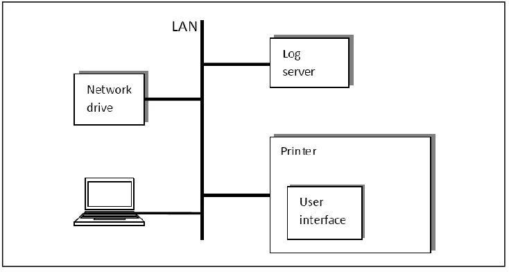
19 for example a document from Microsoft Word, this is sent to the printer over
the local area network (LAN). The printer processes this print job, and shows the printer status on the user interface (e.g., initializing, warming, printing, standby).
For research and development the printer sends internally performed protocol actions over the LAN to a log server, which stores this information in a global logfile, on a network drive (see figure 3).
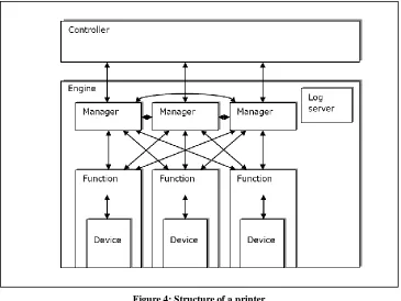
1.2.1 Structure
The printer consists of a well-defined structure, which globally exists of a Controller and an Engine (see figure 4). The Controller is, besides image processing, responsible for the control of the Engine and the information transfer between the user and the Engine. In more detail, it:
communicates with a user to provide information about the configuration (e.g., paper size, print quality, status); assigns print jobs from the user to the Engine;
controls the Engine status to correctly execute send print jobs.
The configuration and error information provided by the Controller to the user is provided by the Engine to the Controller.
The Engine is responsible for the actual printing, it is the part where the high-level control messages are translated into low-high-level system signals. To do so, the Engine consists of several processes:
[image:20.612.135.502.189.385.2] Managers form an interface from the Engine to the Controller, to which a Controller can connect. Each Manager represents a functional aspect of the printer (e.g., error handling, page printing, status control). The required behaviour of a Manager can be established by the use of Functions and other Managers.
Functions are a top-level decomposition to help managers dealing with dependencies and structures of hardware components. A Function controls a coherent set of devices, for instance the paper input. It „converts‟ Engine physical parts to Engine functional parts.
Devices consist of a software part and a hardware part. The software part of a Device is called a Device driver. It controls a coherent set of sensors and actuators, which can be on functional, temporal, or physical level. The hardware part of a device represents an actual part of the Engine hardware, and belongs to the hardware of the printer.
1.2.2 Protocols and logging
The processes of the Engine (managers, functions and devices) and the Controller communicate to each other by means of different protocols, depicted by black arrows in Figure 4.
A protocol is an agreed-upon method of communicating information between two or more entities, using an underlying service or medium [9]. There are two relevant ingredients in the used protocols:
the messages, and their intended meaning;
[image:21.612.113.478.116.390.2]21 Messages contain a label and often an identification number, which
distinguishes the protocol message from messages with an equal label. Identification numbers are also used to match the message with a message response.
Each protocol has its own distinct set of messages, there are no message sets that have messages with an equal label and identification number. In each protocol and between different protocols the combination label and identification number is always unique. Hence printer protocols form a deterministic system.
Protocol messages are not only sent from one process to another, but also to a log server in the Engine (see figure 4). This log server appends the current time to the message and sends the result represented as text string, via the Controller, to the log server outside the printer. In the printer a small buffer stores the latest log messages, which can be used to detect failures by customers. The level of messaging can be adjusted to relief printer processors. Log messages which are sent to the log server form a large logfile, in which the message, the time the message is sent and the involved processes are written (see figure 5). Because this logfile is a sequential representation of parallel communications, and because some messages have to travel a longer way to the Engine log server than others, it can happen that protocol messages are stored in a different order and that timestamps are assigned different from their actual time.
When timestamps are not assigned following the actual time (i.e., an action which is performed earlier than another one, gets a lager timestamp) the logfile is not a correct representation of the order of actions taken in the printer. When these incorrect „timed‟ logfile actions do not have a relation to each other this is not a problem. However, when they do have a relation, verification of these messages will fail. This case is very rare in practice because the extra travel time of log messages is small corresponding to the time between the log messages.
147079644: a_ESM_Printer-func /Process, newstatus=standby, no EI update needed. 147079724: a_ESM_Printer: cancelling transion timer.
147079760: a_ESM_Printer: send m_Set(PowerOffParam = normal). 147079834: a_ESM_Printer: f_UnitStatusChanged(standby)
147079909: a_ESM_Printer: send m_UnitStatus(standby) to Controller. 147079976: a_ESM_Printer: send m_UnitStatus(standby) to ACM Client. 147080499: a_ESM_Printer: p_EIMCacheControl.m_FlushAll send.
147080601: a_EDRouterCheckerPrinter: received unit status (standby) from statusmanager 147080701: a_PPM: received m_UnitStatus(standby).
147080844: a_EIManagerPrinter: Received m_Set on port s_ModuleInformation[5] with data: 147081175: a_DEV_WprStatus:/deviceWprStatus: Received_DeviceInformation
147081716: a_DEV_WprStatus:/deviceWprStatus: Received SUBTYPE_SETREPLY 147081874: a_EIManagerPrinter: Received m_flushAll. Updating all postponed items with 147082986: a_ESM_Printer: p_EIMCacheControl.m_FlushAllDone received.
[image:22.612.138.547.492.709.2]147086744: a_RC_ECadapter:printer: RC-command: ei: setparam moduleId /system paramId 147087766: a_EIManagerPrinter: Received m_Set on port p_Information[1] with data: 147087949: a_SpeedController: @SSL @PROMON Update received: D_InfoSpec:
Note that the logfile also can contain incorrectly ordered messages as result of software failures (i.e., incorrect communicating software), hardware bugs or failures due to incorrect external parameters (e.g., usage of wrong paper or too high environment temperatures).
1.2.3 Test
To be sure different printer processes interact correctly with each other, a printer is extensively tested. Tests are performed in three stages, the stages of the V-model [10] according to which the printer is developed.
A model of the printer is built, which simulates the required system. An embedded prototype is built, with code generated from the model. A final product (i.e., a printer) is built by gradually replacing the
experimental hardware of the prototype by real hardware, until the printer is build in its final form as it will be used and mass produced.
Each of the above printer appearances (model, prototype and final product) follows a V-development cycle itself, including design, build and test activities. This implies that the complete functionality can be tested for the models as well as for the prototype and the final product. However, certain detailed properties cannot be tested on the model and must be tested on the prototype or the final product, for instance, the impact of environmental conditions. The tests performed on the prototype and the final product have to deal with the whole embedded system, instead of only software in the model. These tests produce logfiles besides printed paper.
The evaluation of these tests makes use of these produced logfiles. The evaluation is partly manual and partly automatic. For instance, the check whether bitmaps are printed correctly or not is manual; the check whether the right amount of sheets is printed or not is automatic.
Tests can result in a correct or an incorrect verdict. An incorrect verdict exhibits incorrect printer behavior, which can be divided into:
test-independent incorrect behaviour; test-specific incorrect behaviour.
Test-independent incorrect behavior is in general wrong behavior (e.g., print a sheet without first warming the Engine). This printer behaviour is for all tests unacceptable. It can be recognized by an incorrect order of protocol messages or missing protocol messages, without knowing the performed test.
23
1.2.4 Verification
By performing a test, processes in the printer produce log statements. These log statements are an unambiguous representation of the protocol messages send in the printer during the test, and can be used to verify the behaviour of the printer.
Definition
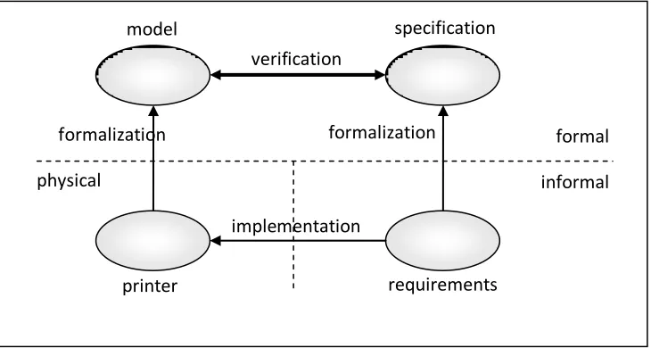
Verification is the mathematical proof of a formal relation between the formal representations of the implementation and the requirements [9] (see figure 6).
The requirements of the printer are formalized, which means: translated from a description in an informal language to a description in a formal language. A formal language is defined by a formal syntax, and has associated semantics, which give precise meaning to expressions in the syntax. The printer itself is also formalized, which means that a formal model is created from the implementation. This model is derived from the logfiles of the printer.
The formal relation between the (formal) specification and the (formal) model defines the behaviour that is allowed in the model by the specification. This relation can be that the model must be included by the specification, or that the model and the specification are equal.
The specification is created manually from the requirements of the printer. The validation of this specification, the check whether the formalization is correct, is a manual task. The model of the printer is automatically created from the logfile and should correspond to the behaviour of the printer.
formal
informal
requirements
printer
implementation
formalization
formalization
model
specification
verification
[image:24.612.136.501.216.411.2]physical
1.3 Outline
The remaining part of this thesis is divided into four chapters:
Chapter 2 (Formal preliminaries) describes labeled transition systems, the composition of these systems and the relation between them. Furthermore, it describes the formal description language LOTOS. This language is used to describe printer requirements.
Chapter 3 (Method) describes the developed method. It describes the preprocessing of the logfile, the creation of a specification, consisting of reference, synchronization and test-specific models and the composition of these models. Furthermore it describes the verification and analysis of the log model with the specification and several alternatives for it.
Chapter 4 (Implementation) describes the developed tool chain, which consists of a preprocessor, a LOTOS editor, two LOTOS compilers and a Testlog verifier. Also alternatives for this implementation are described.
Chapter 5 (Results) shows the practical use of the method and the tool chain. It describes four cases, which describe a subset of the functionality of the printer, and gives results obtained.
25
2 Formal preliminaries
Formal methods is a term used for mathematically-based techniques, used for specification, development and verification of software and hardware systems. They provide formal, unambiguous, models and precisely defined and proved methods that provide a means to verify, validate and test these models. These methods are increasingly used in industry to evaluate correctness [11, 12].
This chapter presents the required preliminaries to understand the method this thesis describes.
Organization of this chapter
Section 2.1 gives information about labeled transition systems, it includes the definition and the composition of these systems and the relations these systems have. Section 2.2 describes the specification language LOTOS, the implementation of the formal definitions in this description language. Each section in this chapter is illustrated with an example.
2.1 Labeled transition systems
DefinitionA labeled transition system (LTS) [13] is a 4-tuple S, L, T, s0 where S is a finite, non-empty set of states;
L is a finite set of labels;
is the transition relation;
s0 S is the initial state
A transition labeled from state s to state s, i.e., (s, , s) T is written as: . This is interpreted as: “when the system is in state s it may perform action and go to state s”. The labels in L represent the observable actions of a system; they model the systems‟ interactions with its environment. Internal
Seek simplicity and distrust it
actions are denoted by the special label L; is assumed to be unobservable for the systems environment. A series of transitions in which at least one with label and zero or more internal actions, from state s to state s’, is written as: s s‟. This is interpreted as: “when the system is in state s it may perform zero or more internal actions, one action , zero or more internal actions and go to state s”.
An LTS can be represented by a graph, where nodes represent states and labeled edges represent transitions.
Example
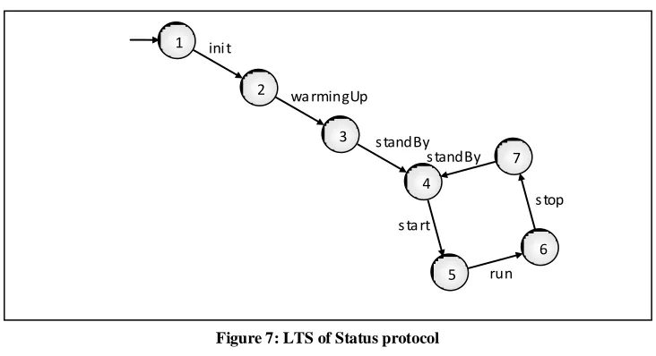
Figure 7 gives an example of an LTS represented by a graph. This figure gives a simplified representation of the Status protocol of a printer.
Figure 7 represents states by numbers and labels by character strings. The LTS has a set of states, S: {0, 1, 2, 3, 4, 5, 6}, a set of labels, L: {init, warmingUp, standBy, start, run, stop}, a set of transitions, T: {(0, init, 1), (1, warmingUp, 2), (2, standBy, 3), (3, start, 4), (4, run, 5), (5, stop, 6) , (6, standBy, 3)}, and an initial state, s0: 0.
2.1.1 Composition of LTSs
A composition of different LTSs, LTS1 and LTS2, is written as: LTS1 |[ G ]| LTS2,
where G is a set of labels (see Section 2.2.1 below). This is interpreted as: “LTS1 and LTS2 synchronize on all transitions with a label of the set G, all
transitions with other labels are interleaved” (i.e., in the composition each order of these transitions is possible). It means full interleaving if the label set G is empty (G = ), full synchronization, if the label set G equals the union of the label sets of the synchronizing LTSs and if this label sets are equal (G = L(LTS1) L(LTS2) and L(LTS1) = L(LTS2) ), and partial interleaving otherwise.
Synchronization can occur if both systems are able to perform a transition with a similar label. This implies that LTSs can also both block the occurrence of
1
7
6 5
4 3
2 ini t
wa rmingUp
s tandBy
s ta rt s tandBy
s top
[image:27.612.111.477.259.458.2]run
27 synchronization. Interleaving occurs when one of the LTSs can perform a
transition that is not a synchronizing transition.
Example
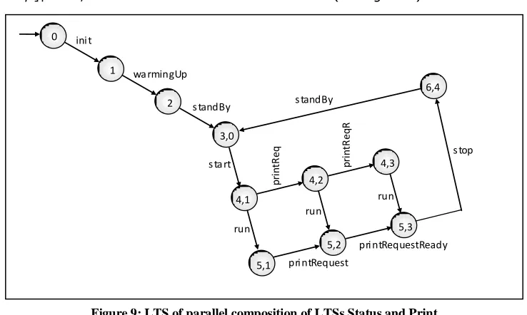
A composition LTS is created from the LTS of Figure 7 with the one in Figure 8. The latter representing a simplified version of the Print protocol of a printer (see figure 8). The transitions start and stop in the LTS in this figure are not part of the protocol, they are appended for this example.
The resulting LTS, created using the composition operator |[G]|: Status |[start, stop]| Print, contains 11 states and 13 transitions (see figure 9).
In this composition only transitions start and stop are synchronizing, all other transitions are interleaved. However, the LTS of the print protocol (figure 8) does not have transitions before start and after stop, so the only actually
1 2 3 4 5 s ta rt
pri ntRequest pri ntRequestReady s top ini t wa rmingUp s tandBy
s ta rt
[image:28.612.130.500.202.373.2]s tandBy s top run pri ntRequest pri ntRequestReady run run pr in tR eq pr in tR eq R 0 6,4 4,1 3,0 2 1 5,1 4,3 4,2 5,3 5,2
[image:28.612.132.501.408.629.2]Figure 8: LTS of Print protocol
28
interleaving transitions in Figure 9 are run, printRequest and printRequestReady.
2.1.2 Relation between LTSs
LTSs are used to model the behaviour of systems, such as distributed systems and protocols. These systems, formalizations of processes, can be compared using formal relations, which are known from literature [14, 15]. In this thesis only the trace inclusion relation is important.
The trace inclusion relation compares different LTSs by means of their traces. A trace is defined as a sequence of actions which exist in a specific LTS.
Definition
A formal notation of a trace is:
traces (s) = { L* | s }
where s is an arbitrary LTS, L the label set of s and L* the set of sequences in L.
Example
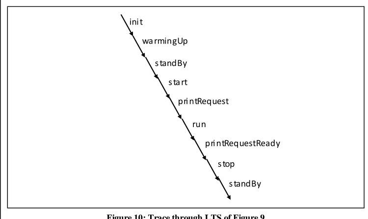
Figure 9 contains infinitely many traces, one of them is depicted below (see figure 10).
The trace in Figure 10 starts with the first transition of the LTS of Figure 9, and forms a trace through. The cycle in the LTS of Figure 9 causes an infinite number of traces.
A trace inclusion relation is intuitively defined as follows: if LTS P is trace included in LTS Q, the traces formed by the transitions of P, are also traces in Q. The other way around is not required, neither forbidden.
run
s tandBy pri ntRequest
pri ntRequestReady
s top ini t
wa rmingUp
s tandBy
[image:29.612.105.480.350.574.2]s ta rt
29 Definition
A formal notation of the trace inclusion relation [13] is: P tr Q =def traces(P) traces(Q)
[image:30.612.128.502.176.371.2]where LTS P is trace included by LTS Q. Example
Figure 11 shows two LTSs, LTS P and LTS Q.
LTS P is trace included in LTS Q since all traces of LTS P are traces of LTS Q. The traces of LTS P are traces(P): {init; init, printRequest; init, printRequest, printRequestReady} and the traces of LTS Q are traces(Q): {init; init, printRequest; init, printRequest, printRequestReady; init, printRequest, printRequestReady, stop}.
LTS Q is not trace included by LTS P since the trace: init, printRequest, printRequestReady, stop, is a trace in Q but not in P.
The relation used in this thesis is the trace membership relation. This is a simplification of the trace inclusion relation, since it describes the „inclusion‟ of one trace into an LTS. This relation is defined as: the trace is an element of the set of traces of LTS Q
Definition
The notation for the trace membership relation is: traces(Q)
Where is a trace and Q an LTS.
The Trace inclusion relation and the trace membership relation are similar when LTS P consists of only one trace (like is one trace).
If a composition of two LTSs, made by synchronizing on shared labels, contains a trace, then each of the individual LTSs contains a trace. The other way
start
printRequest
printRequestReady 1
2
3
4 1
2
3
4
5 start
printRequest
printRequestReady
stop
LTS P LTS Q
around also holds: if two LTSs both contain a trace, the composition of these two LTSs also contains a trace, when it is synchronized on shared labels. In a formal notation:
Where the label set of the composition is the union of the label sets of both LTSs:
Where L is the label set of the composition, Lp is the label set of LTS P and Lq is the label set of LTS Q. The notation means: for which holds , in this case it means that is a trace only containing labels from the label set .
2.2 LOTOS
The representation of a printer specification in an LTS, like Figure 7 or Figure 8, is not directly suitable to describe the correct behaviour of the requirements of a printer. There are two reasons for that:
a composed model of a printer can easily have billions of states, drawing them is cumbersome;
transitions can have corresponding data values, expressions and constraints, which cannot easily be modeled in an ordinary LTS.
To overcome these issues, another way of representing a transition system is needed. In this thesis the specification language LOTOS (Language of Temporal Ordering Specification), a process algebraic language, is used [5].
LOTOS has been developed for the formal description of the Open system Interconnection (OSI) architecture within the International Organization for Standardization (ISO), although it is applicable to distributed, concurrent systems in general.
In LOTOS a system is seen as a set of processes which interact and exchange data with each other and with their environment. The language consists of complementary formalisms for data and control. The control part, basic LOTOS, a CCS/CSP- based language, is a subset of the language where process synchronization is achieved, but without data exchange [6]. The data structures of LOTOS are derived from the specification language for abstract data types ACT ONE [7, 16]. Only data types (called sorts in LOTOS) and value expressions of ACT ONE are used and described in this thesis.
2.2.1 Basic LOTOS
In basic LOTOS, behavior is described by behaviour expressions [13]. The syntax for a behavior expression B, is the following:
31 The action prefix expression a; B, with a L, the set of labels of the
system, describes the action a (comparable with a transition in an LTS) and then behaves as B. The semantics for this axiom, usually formally defined by means of axioms and inference rules, is:
This axiom is to be read as: an expression of the form a ; B can always make a transition to a state from where it behaves as B.
The expression i ; B is analogous to a ; B, the difference being that i denotes an internal action in the transition system:
The choice expression , where is a countable set of behaviour expressions, denotes a choice of behaviour. It behaves as any of the processes in the set . It is formally defined by the inference rule:
This inference rule is to be read as follows: suppose that we know that B can make a transition to B; moreover we have that B and is any observable or internal action, then we can conclude that can make the same transition to B.
B1 [] B2 is used as an abbreviation of {B1, B2}, i.e., B1 [] B2
behaves as either B1 or B2. The expression stop is an abbreviation for
, i.e., it is the behaviour which cannot perform any action, so it is the deadlocked process.
The parallel expression B1 |[ G ]| B2, where G L, denotes the parallel
execution of B1 and B2. In this parallel execution all actions in G must
synchronize, while all actions not in G (including ) can occur independently in both processes, i.e., interleaved. || is used as an abbreviation for |[ L ]|, i.e., synchronization on all actions except , and ||| as an abbreviation for |[ ]|, i.e., full interleaving and no synchronization. The interference rules are as follows:
The name P can be used in behaviour expressions to stand for the behaviour expressed by its corresponding behaviour expression. Formally:
The expression stop denotes a valid end expression.
As usual parentheses are used to disambiguate expressions. If no parentheses are used „;‟ binds stronger than „[]‟, which binds stronger than „|[ G ]|‟. The parallel operators read from left to right; they are not associative for different synchronization sets.
Example
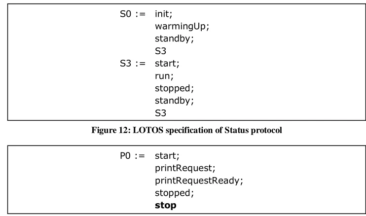
To illustrate this syntax, the examples from Figure 7 and Figure 8 are written in LOTOS (see figure 12 and figure 13).
2.2.2 Full LOTOS
Full LOTOS, or LOTOS, has the advantage over (basic) LOTOS that it has the ability to model with data types.
In full LOTOS, the semantics of parallel composition is unchanged with respect to basic LOTOS. Interprocess communication may still occur when two processes composed in parallel are offering the same action (a transition in an LTS). An action in full LOTOS, which can exchange data values, is formed of three components: a gate, comparable with a label in an LTS; a list of events; and an optional predicate [8].
S0 := init;
warmingUp; standby; S3 S3 := start;
run; stopped; standby; S3
P0 := start; printRequest;
printRequestReady; stopped;
[image:33.612.104.475.287.506.2]stop
Figure 12: LOTOS specification of Status protocol
33 Processes synchronize their actions, provided that they name the same gate,
that the lists of events are matched, and that the predicates, if present, are satisfied. An event can either offer (!) or accept (?) a value. The synchronization rule of basic LOTOS is replaced by synchronization rules in full LOTOS. In full LOTOS there are three kinds of synchronization:
Value matching:
E1 and E2 are expressions and must belong to the same data type. It will succeed if E1 equals E2 from the specification of the common type.
Value passing:
Expression E must belong to the data type S. It will succeed, replacing x by E in B2.
Negotiation:
It will succeed, becoming x = y = v, where v is some value in the specified data type S
When a predicate is used, e.g., a[E1 = E2], synchronization can only take place if the result of the predicate evaluates to true, i.e., E1 equals E2.
Example
[image:34.612.152.502.170.432.2]When data types and data are added to a specification, the actions of the specification contain besides the action name, the variable name and the variable type (see figure 14).
Figure 14 specifies the Print protocol of Figure 8, extended with a variable of the data type Natural. The transition printRequest needs a Natural value before it can synchronize, another process has to pass this value. When this condition is met, the transition printRequestReady matches the obtained value with the
P0 := start;
printRequest ? id:Nat; printRequestReady ! id; stopped;
[image:34.612.130.504.533.624.2]stop
next transition of the synchronizing process. An example of a process that can synchronize with this process is given in Figure 15.
Figure 15 depicts an arbitrary process (P1) that can synchronize with process P0 of Figure 13 (P0 || P1). After the transition printRequest the value of id is 23. This value matches in the transition printRequestReady, so synchronization can be obtained.
An alternative for the construction of value passing and value matching, as depicted in Figure 14, is a construction with value passing and a constraint (see figure 16).
The process in this figure also synchronizes with process P1 of Figure 15 (P1 || P0). The action printRequest again synchronizes passing the Natural 23 to the variable id1. The action printRequestReady of P0 tries to synchronize with printRequestReady of P1, first passing the Natural value 23 to id2. The synchronization is successful when the value of id1 is equal to that of id2, like the constraint.
P0 := start;
printRequest ? id1:Nat;
printRequestReady ? id2:Nat [id1 = id2]; stopped;
stop P1 := start;
printRequest ! 23; printRequestReady ! 23; stopped;
[image:35.612.103.481.121.201.2]stop
[image:35.612.108.477.316.392.2]Figure 15: Arbitrary LOTOS process
35
2.2.3 LOTOS example
Besides the description of the behavior of a LOTOS specification, the total specification is enclosed in specification keywords following the LOTOS syntax [5,6,7,8] (see figure 17).
A specification starts with SPECIFICATION and ends with ENDSPEC. In between these keywords one or more processes, libraries and transitions can be defined. Each process starts with the keyword PROCESS and ends with ENDPROC, each library instantiation with LIBRARY and ENDLIB. EXIT or NOEXIT defines respectively whether the process can terminate successfully or not. Below the statement WHERE an earlier used process is defined.
Declarations of types have to be placed before the use of a type instance. Processes and transitions can be placed in parallel or after each other. Libraries are at compile time pasted in the specification at the place of the library declaration. Hence a library file contains normal LOTOS code with LOTOS syntax.
SPECIFICATION Print [start, printRequest, printRequestReady, stopped] :NOEXIT
LIBRARY
NATURAL ENDLIB
BEHAVIOUR
Protocol [start, printRequest, printRequestReady, stopped] :NOEXIT
WHERE
PROCESS Protocol [start, printrequest, printrequestready, stopped]
:NOEXIT
start;
printRequest ? id : NAT; printRequestReady ! id; stopped
ENDPROC
[image:36.612.136.498.154.480.2]ENDSPEC
37
3 Method
The verification and analysis of the printer by means of its logfiles requires three ingredients:
a logfile, which has to be verified and analyzed;
a specification, which defines the correct behaviour of the printer;
a relation between the logfile and the specification.
This chapter describes these three ingredients in the developed method
Organization of this chapter
Section 3.1 describes the log model. Section 3.2 describes the specification, a formalization of the requirements of the printer, in different models: reference, synchronization and test-specific models. Section 3.3 describes the verification and analysis of a logfile. Section 3.4 describes an alternative.
3.1 Log model
A logfile contains all actions and details of actions of logged protocols, for example: the time on which the action is performed, the name of the sending or receiving process, the action label and an action identification number. To deal with this information the logfile is transformed into a log model. This transformation is done into two parts: filtering and formalization. Filtering keeps only actions of the protocols to verify and formalization puts these actions in the correct syntax. The transformation of the logfile has three reasons:
not all logged protocols are formalized in the specification, the formalization of a subset of the requirements only makes sense when also a subset of the logfile is taken;
not all details in the logfile are used in the specification. The actions in the logfile contain a large amount of details, used for debugging, the actions in the specification do not. These details are not used for the verification and analysis;
The ability to simplify means to eliminate the unnecessary so that the necessary may speak
not all statements in the logfile have the same syntax. Since the logfile is originally used for debugging, the logged actions do not always have a standardized structure. The formalization covers the inconsistent formats of the notation of logged actions.
When coding rules are applied strictly and logged actions do have the same syntax, the transformation can be brought back to filtering.
The resulting formalized logfile is called log model. This model contains only actions of protocols modeled in the specification and has a well-defined structure. The structure of the log model satisfies the Sequence format rules [17]. A log model consists of a sequence of transition labels, each possible followed by one or more identification numbers or other naturals (e.g., time). Since the syntax of the logged actions differs per protocol, the transformation is different for each protocol. If the syntax of a protocol is known, the transformation is done automatically.
Example
Figure 10 (page 27) depicts a log model in which the printer printed one sheet. This model can be represented in a sequence (see figure 18).
3.2 Specification
To verify and analyze the logfile of a printer, a notion of a correct logfile is needed. The logfile can be verified against the requirements of the printer, which describes the printer behaviour informally, but this description often is not unambiguous. To overcome this problem the requirements of the printer are formalized, which gives a formal specification.
A disadvantage of the formalization of the requirements is their large size. A printer is a complex machine, which has many complex requirements. This means that a simple verification must be preceded by the huge task of formalization. To overcome this barrier AVATR is developed to be able to use a subset of the formalized requirements.
When formalizing the logfile, the actions modeled in the specification must be known in order to verify and analyze the printer on those actions.
init;
warmingUp; standBy; start;
printRequest !3; run;
printRequestReady !3; stop;
[image:39.612.103.479.341.476.2]standBy;
39 The sections below describe the formal specification, which consist of three
types of models: reference, synchronization and test-specific.
3.2.1 Reference model
A reference model is a formalization of a small subset of the requirements of the printer. This can be a coherent part, like all the actions of one protocol, but this can also be an arbitrary part of the actions of a process. However, a small coherent part is easier to maintain and more generally applicable than a large model. This is especially true for printers under development, since they might change.
A typical coherent subset of a printer is a protocol. The requirements of a particular protocol, given in English text, consist of a description of actions and responses, illustrated with sequence diagrams.
Protocol actions and responses are modeled in one model without distinction between them, since they belong to the same protocol. By modeling them in the same model, the order of action and response is defined.
Example
From the requirements of the Status protocol a reference model is extracted, which contains all protocol actions and responses in all allowed orders (see figure 19).
At the same manner a reference model of the print protocol is drawn (see figure 20, slightly different from the model given in figure 8 on page 27 because the start and stop actions do not belong to this protocol).
0
6
5 4
3 2
1 ini t
wa rming
U
ps tandBy
s ta rt s tandBy
s top
run
[image:40.612.129.500.376.557.2]In this reference model, each transition has an integer variable to store an identification number. This makes it possible to distinguish transitions within several protocol instances of this protocol.
3.2.2 Synchronization model
A reference model describes a small subset of the printer functionality. To verify a larger part of the printer there are two options:
model a larger part of the functionality in one reference model;
create a composition of small reference models.
A model of a larger part of the functionality of the printer shatters the maintainability of the reference models, since there are no restrictions to which extent a model can be enlarged, the overview is easily lost.
A composition of more small reference models preserves maintainability of the approach but loses the obligatory order between the transitions of the different reference models. A full interleaving of small reference models is not by definition correct: some process actions are not allowed in arbitrary order. To overcome this problem, another type of models is defined: a synchronization model.
A synchronization model defines the allowed order of transitions of the different reference models; it does not define new actions. It contains a subset of actions of two or more reference models, with the obligatory order between them. In this model only actions of the related reference models that have order constraints are modeled, i.e., actions which always happen before or after another action. Actions without constraints do not need to be modeled, since they are already full interleaved.
A synchronization model provides flexibility to the specification. Due to this model small general reference models can be created and combined in every way. The composition of a synchronization model and a reference model is given by the parallel LOTOS expression (section 2.2):
0
1
2
pri ntRequest ? id : Na t
[image:41.612.103.480.103.211.2]pri ntRequestReady ! id
41 reference model1 |[ G1 ]| synchronization model |[ G2 ]| reference model2
or, since ||| and |[]| are associative and
G
1G
2=
, by:reference model1 ||| reference model2 |[ G1 G2 ]| synchronization model
Where G1 and G2 are label sets with order constraints, which contain
respectively labels of reference model1 and of reference model2.
When a synchronization model is used, all the transitions in it must be placed in one of the label sets G1 or G2. When the sets G1 and G2 are empty, full
interleaving is achieved, as if there is no synchronization model. If these sets are non empty, partial interleaving is achieved between the reference model and the synchronization model. If two reference models are completely independent of each other, no synchronization model is needed.
Example
The actions of the Status protocol, Figure 19, and the Print protocol, Figure 20, have an obligatory order. The actions in the Print protocol are only allowed after the Status protocol action standby. This obligatory order is drawn in a synchronization model (see figure 21).
This figure shows a model that defines the order of the actions standBy and printRequest. printRequest is only possible after a first occurrence of standBy, after which the action standBy is still allowed.
The models of the Status protocol and the Print protocol and the synchronization model (Figure 21) are composed together to form a total specification (see figure 22) with the LOTOS expression:
Status|[ standBy ]| synchronization |[ printRequest ]| Print
0 1
pri ntRequest s tandBy
s tandBy
3.2.3 Test-specific model
Reference and synchronization models are sufficient for test-independent verification and analysis, the verification and analysis of test-specific behaviour needs more information, e.g., information about the specific test which was performed while the printer produced the logfile. This extra information is modeled in a test-specific model.
A test-specific model contains actions of protocols on which the test-specific constraints apply. These test-specific constraints are a specific situation in the reference models that describe its specification more closely, e.g., a reference model specifies which actions are needed to print a page, a test-specific model specifies the number of pages in the specification.
The composition of a test-specific model with the reference and synchronization models is similar to that of a synchronization model with a reference model (section 3.2.2).
Example
The specification of Figure 22, describes a printer which prints one page: there is only one action printRequest in one trace possible. To verify a print job of more pages, more Print models have to be composed. This is for sake of a clear overview not drawn in an LTS. Test specific situations could be the number of printed pages before the second visit of the state standby, or the total amount of printed pages.
0 3 2 1 ini t wa rmingUp s tandBy s tandBy 6 9 8 run run s top 6 5 4 7 s ta rt
run s top 3 s tandBy 5 pri ntRequest pri ntRequestReady 6 5 s top s ta rt s ta rt
pri ntRequestReady pri ntRequestReady pri ntRequestReady pri ntRequest pri ntRequest pri ntRequest s tandBy
43 To verify that the printer prints only one page, and to exclude the printing of
no pages or a second page, a test-specific model is created (see figure 23).
This model is synchronized with the LOTOS expression:
specification
|[
printRequest
,
stop
]|
test-specific model
Every time an action printRequest is done, the counter n increments by one, every time the action stop is done, the counter n is checked to be one. When the counter exceeds 1, the stop action can not be performed since n is not equal to one and the verification fails. The number of pages can easily be adjusted.
Another example of a test-specific model deals with time. If a printRequest is done, it can be interesting to verify that the corresponding printRequestReady is performed within a given amount of time, for example 100 micro seconds. This can also be specified in a test-specific model (see figure 24).
3.3 Correctness relation
The log model represents in one sequence the behaviour of the printer. The specification, consisting of reference, synchronization and test-specific models, shows all possible correct sequences of the printer. The relation between this log model and specification determines whether the log model is correct or not
n
pri ntRequest
n = n + 1
s top [ n = 1 ]
n = 0
0 1
pri ntRequest ?time1:NAT
[image:44.612.131.500.118.252.2]pri ntRequestReady ?time2:NAT [ti me1 + 100 > ti me2]
Figure 23: Test-specific model test print of one sheet
[image:44.612.127.504.465.582.2](section 1.1.3). This relation is a trace membership relation; a log model is a member of the traces formed by the specification, if the printer behaves correctly (section 2.1.2). The verification of the printer, by means of a logfile, is the check for existence of this relation. The analysis of the printer, when this relation does not exists, determines the first failure.
The specification of the printer is deterministic (i.e., it does not contain states with outgoing transitions with an equal pair: action name, identification number, Section 1.2.2). Hence, the search of the trace inclusion relation between the log model and the specification is a deterministic process, which does not require any search algorithms; there is only one way to match every transition given the previous transitions.
The simplest algorithm to verify the log model with the specification starts with the first log model transition, if this transition matches one of the outgoing transitions from the initial state of the specification; this transition is correct and the new state of the specification is remembered. Subsequently, the next log transition is matched to an outgoing transition of the new specification state. This is repeated until the last log model transition has been reached or until a log model transition does not match with a specification transition. In the latter case, the part of the log model checked so far is printed, which leads to the unexpected transition.
To verify whether the last log model transition corresponds with a correct end transition of the specification, a final transition is appended at the end of the log model and after each correct end transition in the specification. This final transition must have a label different from all other used transition labels in the specification or log model, to distinguish between them. In a model more final transitions can be defined, which are treated the same as other transitions in the model. If more protocol instances are used, more final transitions can be appended. However, for every logfile only one final transition is needed in the specification, since a log model is a sequence of transitions which has only one last transition.
3.4 Verification
Specification models are composed together to form a larger specification (section 3.2.2). Since independent sub-models of the specification are composed in parallel, the composition can describe a very large transition system.
To handle large specifications efficiently, two verification methods are applied: the generation of the composition of the specification models on-the-fly
with the verification;
the verification of each specification sub-model separately.
45 The sections below describe the on-the-fly composition, the separate
verification of sub-models, and the composition of the specification models with the log model.
3.4.1 On-the-fly composition of specification.
The log model consists of one sequence of actions of the printer and the specification consists of all correct sequences (Section 1.1.3). Each log model transition can be matched on one specification transition, starting with the first. Since the specification is deterministic, only one specification transition can match with a log model transition. For each log model transition only one specification transition is relevant and other transitions do not match. These other transitions do not have to be created in the transition system. Hence the on-the-fly created specification transition system is smaller than the original composition of the specification models.
3.4.2 Separate verification of specification models
Besides the on-the-fly verification, the printer functionality can be verified and analyzed separately, by means of separate models. This holds for each model, whether it is a reference, synchronization or test-specific model.
A reference model can be verified stand alone, since it describes only one (stand alone) protocol. For this verification only the transitions used in the specification are formalized in the log model.
The verification of synchronization and test-specific models is done the same way. Only the transitions used in the particular specification models are formalized in a log model, and only the functionality described in the particular specification model is verified.
When a log model is trace included in a composed specification, the individual parts of this specification include traces of „sub-log‟ models. These sub-log models contain only the functionality (actions) of the particular model to verify (see section 2.1.2). This is the same as the verification of only the Print protocol or only the Data protocol.
3.4.3 Composition of specification with log model
An alternative for the previous described methods is the creation of a
composition of the log model with the specification models and check whether the last transition of this composition is reached.
47
4 Implementation
The AVATR method, described in Chapter 3, is implemented. The described models are implemented in the formal specification language LOTOS and the trace inclusion relation is implemented in the AVATR tool chain.
Organization of this chapter
Section 4.1 describes the motivation for the specification language LOTOS. Section 4.2 describes the individual parts of the tool chain, a LOTOS editor, LOTOS compilers, a preprocessor and a Testlog verifier. Section 4.3 describes two alternative specification languages: CRL and a general programming language, and five alternative Testlog verifier implementations: TETRA, UPPAAL, TorX, CADP Bisismulator and the CRL toolset.
4.1 Specification language
AVATR models are described in the formal description language LOTOS [5, 6, 7, 8], which has been introduced in Chapter 2.
Requirements for a language are:
the language has to be well-documented;
the language must be able to implement transitions;
the language must be able to use instances of the data type Natural to express identification numbers and time.
Tool support is an advantage.
The language LOTOS satisfies these requirements. It is a well-documented language, since it is a standard of the International Standard Organization. Furthermore it is possible to describe transitions and data types, since the language is designed to specify interaction of processes [5].
If I had eight hours to chop down a tree, I’d spend six hours sharpening my axe
Besides these requirements, LOTOS has the following advantages: LOTOS supports enforced synchronization, which means that
synchronizing transitions can not be taken without synchronizing partner.
there are tools available which provide the needed trace inclusion functionality.
However, LOTOS has some disadvantages:
there are no global variables, data type instances have to be passed forward with the call of a process;
there are no defined data types, only abstract data types can be used. When a data type is needed it has to be defined, which means that each data type instance and each operator have to be defined. This is called an abstract data type. The needed natural numbers range from zero to some billions (timestamps are 32 bits).
4.2 The tool chain
The developed AVATR tool chain, which implements the AVATR method, exists of five tools (see figure 25):
a LOTOS editor;
a LOTOS functional compiler;
a LOTOS abstract data type compiler; a preprocessor;
a Testlog verifier.
49 The implementation in a tool chain provides flexibility since individual tools can
be changed without changing other parts of the tool chain, provided that the specified interfaces are implemented. Some of these interfaces are specific for the used tools (e.g., preprocessor/ Testlog verifier interface), which makes it hard to replace only one specific tool; instead two tools have to be replaced.
The next sections describe the particular tools in the AVATR chain.
4.2.1 The LOTOS editor
The LOTOS editor can be any text editor, preferably with LOTOS syntax highlighting. In this project the editor VIM (Vi IMproved) [2] is used. VIM is a highly configurable text editor built to enable efficient text editing. It gives the user the possibility to create and edit LOTOS specifications (section 3.2). Text editors do not give the overview given by graphical edit