W
W
ith the surge of international terrorism and the in-creased use of explosives in terrorist attacks, law enforcement agencies throughout the world are faced with the problem of detecting hidden bombs in luggage, mail, vehicles, and aircraft, as well as on suspects. This has become a major analytical problem, which requires highly sensitive, specific, and fast methods for its solution.Another worldwide problem involving explosives is the detection of landmines. According to the United Nations, 120 million unexploded landmines, most of them unmarked, are buried in 70 countries. The development of efficient and cost-effective landmine detection devices has become an ur-gent worldwide necessity.
Because canines have excellent smell-detection capabili-ties and can perceive very small quanticapabili-ties of odorants, they have been used successfully for sniffing out drugs, agricul-tural products, fugitives, cadavers, hidden explosives, and
Jehuda Yinon
University of Central Florida
Detection of
Explosives
by Electronic Noses
Handheld chemical-sensing
systems come in several varieties
and offer advantages over the
traditional bomb-sniffing dog.
landmines (1). The sense of smell, or olfaction, is an important sense for both humans and animals, because it allows them to identify food, provides sensual pleasure (e.g., the scent of flow-ers or perfume), and warns them of dangflow-ers (e.g., spoiled meat). The olfactory epithelium, situated under a dog’s forehead, is a membrane covered with receptors that has a large, convoluted sur-face area. For example, in the German shepherd, the sursur-face area is ~100 cm2compared with 3 cm2for a human (2). Each receptor is connected by its own nerve fiber to the olfactory bulb, where the signals are processed before being sent to the brain. A good search dog can recognize at least 14 different types of odors, including drugs, human odors, and explosives. Moreover, because the dog’s nares (or nostrils) are completely separated by a septum, it has an essentially bilateral separation of olfactory stimuli, which allows it to determine the direction or location of an odor’s source (3). However, there are several problems associated with using dogs to detect explosives. They require rigorous training, test-ing, and validation exercises in various operational scenarios with different types of explosives. Dogs are trained to identify specific explosive ingredients rather than specific products; for example, a dog is trained to detect nitroglycerin instead of dy-namite, so the explosive’s exact formulation is not important. Dogs learn to discriminate between the vapor of that substance and other odors in the environment.
A dog’s performance, which requires testing and constant retraining, also frequently declines over time and after extensive fieldwork. For example, when performing a search task, dogs become tired after 30–120 min, which suggests the need for two or more dogs at each location (3). In addition, the volume of flow at airports makes the use of dogs very expensive. For example, to achieve optimal performance, each dog requires an assigned handler, which increases costs because the canine detec-tor is really a dog–handler team. Dogs also show behavioral vari-ations and changing moods, which are difficult to monitor in a quantifiable way.
Electronic noses
With a clear understanding of the advantages and disadvantages of using canines, researchers are interested in developing hand-held and mobile devices, called electronic or artificial “noses”, which mimic bomb-sniffing dogs without having their draw-backs. An electronic nose is usually composed of a chemical-sensing system and a pattern-recognition system, such as an ar-tificial neural network. Each vapor presented to the sensing system produces a signature or “fingerprint”. Presenting many different chemicals to the sensor yields a database of fingerprints, which the pattern-recognition system uses to recognize and au-tomatically identify each chemical.
Sensor arrays offer several advantages over single sensors— sensitivity to a wider range of analytes, better selectivity, multi-component analysis, and analyte recognition—rather than mere detection. Sensor arrays are more analogous to olfaction systems containing multiple receptors, whose responses are interpreted by neuron odor recognition processes. However, researchers have developed some single sensors to react to specific explosives such as trinitrotoluene (TNT), the explosive component in most land-mines. Such sensors can detect very low levels of explosive vapor. In addition, various types of mass spectrometers, gas chroma-tographs, and ion mobility spectrometers have been miniaturized into mobile and handheld explosive “sniffers” and landmine de-tectors. They are considered electronic noses because they are capable of detecting and identifying very low concentrations of vapors, thus imitating a canine’s capabilities. These sniffers have been described in great detail elsewhere (1, 4, 5).
Amplifying chromophore quenching
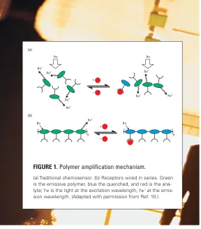
Several electronic noses use fluorescent polymers—which react to volatile chemicals such as nitrogen-based compounds from explosives—as chemical detectors. Conventional fluorescence detection normally measures an increase or decrease in fluores-cence intensity or an emission wavelength shift that occurs when a single molecule of the analyte interacts with an isolated chro-mophore. In that case, only the chromophore that interacts di-rectly with the analyte molecule is quenched; the remaining chro-mophores continue to fluoresce (Figure 1a).
A variation of this approach is the “molecular wire” config-uration, in which the absorption of a single photon of light by any chromophore will result in a chain reaction, quenching the fluorescence of many chromophores and amplifying the sensory response by several orders of magnitude (Figure 1b) (6). One example of this is a polymer used by Nomadics (6–8), which was originally developed by Swager’s group at the Massachusetts In-stitute of Technology (9–11). The polymer reacts with aromatic nitrocompounds, and thin films of it display high-fluorescence quantum yield and stability for the vapors of TNT and 2,4-dini-trotoluene (2,4-DNT), in particular. This conjugated polymer consists of three-dimensional pentiptycene groups. The back-bone of the polymer acts as a molecular wire, enabling the prop-(a)
hν
hν′
hν′
hν′ hν′
hν′ hν′
hν′ hν
+
–
– + hν′
hν
n
hν
n
[image:2.612.6.294.5.333.2](b)
FIGURE 1.Polymer amplification mechanism.
agation of an exciton (a migrating quantum of electronic energy) that can rapidly propagate along the entire polymer chain. Thin films of these materials coated onto a suitable substrate can form the sensory element of a detection system.
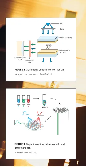
Figure 2 is a schematic of the basic sensor design. A blue light-emitting diode (LED) is used as the fluorescence excitation source. The light emitted by the LED passes through a lens and a filter, al-lowing only a narrow-wavelength band of light centered at 430 nm to impinge on the polymer film, which is coated on two thin glass sheets. A pump pulls in air samples across the coated glass sheets. If the air sample contains explosive vapors, the photomultiplier detec-tor will sense a decrease in light intensity and trigger an alarm. Binding analytes to films is reversible, and a flow of clean air over the films will purge the analyte, returning the fluorescence intensity to near the initial baseline reading. Under field condi-tions, typical recovery times after registering “hits” are 5–10 s for TNT, which recovers more slowly than other nitroaromat-ic compounds because of its stronger interactions with the polymer. The sensor was originally designed to detect vapors of DNT and TNT emanating from landmines. Field tests yielded a detection limit in the femtogram range for TNT (12).
The sensor was also adapted to locate explosives under water (13). The sensor package consists of two watertight boxes. The first box contains a sensing head that consists of a glass wave-guide coated with a thin film of the fluorescent polymer. The coating on the glass rod is illuminated with light from a laser diode source, which causes the polymer to fluoresce. When the coating is exposed to water containing TNT, the intensity of the emission from the polymer, measured with a photomulti-plier, decreases in proportion to the quantity of TNT in the water. The second box contains a peristaltic pump to control sampling and water flow through the sensor.
Fiber optics and beads
To truly mimic a biological nose requires a detector with mil-lions of sensors. Walt and his group have developed an explo-sives sniffer that uses a complex sensor array of fiber-optic ca-bles (14 –18). The sniffer samples the air and watches for the sensors’ color changes. Each sensor produces a different reaction to the same chemical—one sensor may change from blue to green in the presence of nitrogen, whereas another may change from blue to red. Each odor, therefore, creates a different pattern that can be stored in a computer database.
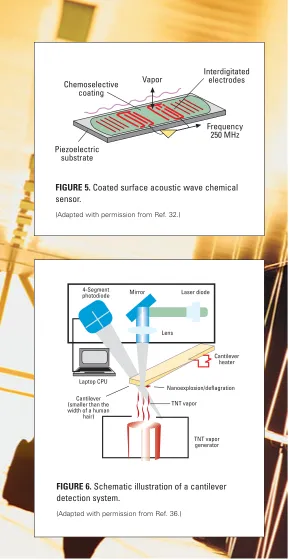
These arrays are prepared by randomly distributing a mixture of thousands of microsphere sensors (beads), each belonging to a dis-crete class, on an optical substrate containing thousands of mi-crometer-scale wells. Each type of bead is encoded with a unique signature, which can be used later to identify its location (Figure 3). A mixture of sensor beads is prepared by combining aliquots from three stock solutions, each containing a different type of poly-mer/dye (e.g., Nile red) sensor suspended in a solution. A drop of the mixture is placed onto the distal tip of an etched imaging
fiber. After the beads have settled in random locations throughout the well array, they are identified and categorized by their charac-teristic responses to a test vapor pulse. The beads are self-encoded, and the signal of each bead is used to identify it and map its po-sition in the array. The signals shown in Figure 3 represent re-sponses from three different bead types—which are assembled in separate image guide microwell arrays—to three different vapors. The sensor array is positioned on an imaging system with a CCD camera detector, and fluorescence changes are monitored before, during, and after a vapor pulse is presented. Upon expo-sure to a vapor, the sensor recognizes the intensity and wavelength shifts that are used to generate fluorescence response patterns, which are, in turn, used to construct a pattern-recognition com-putational network. Subsequent exposure to the same analyte vapor enables the network to identify the vapor by its character-istic response pattern.
Interference filter
Sample
LED
Lens
Glass substrate
Pentiptycene polymer
[image:3.612.326.606.7.551.2]Photomultiplier tube
FIGURE 2.Schematic of basic sensor design.
(Adapted with permission from Ref. 10.)
Mixture Type
A
Type
B
Type C
+ +
FIGURE 3.Depiction of the self-encoded bead array concept.
A cross-reactive optical microsen-sor array was built to detect nitroaro-matic explosives’ vapors (16). Using thousands of identical microsensors permits sensor responses to be com-bined, which reduces sensor noise and enhances detection limits. De-tection limits for 2,4-DNT and TNT were in the low parts-per-billion range.
This technology was used to de-velop a sniffer to detect 2,4-DNT vapor on soil surfaces above buried TNT landmines (17). The system uses two types of fluorescence-based vapor sensors. One type is a pentipty-cene-derived fluorescent polymer (9), which is a semiselective sensing mate-rial for nitroaromatic compounds,
whereas the other type is designed to be nonspecific and cross-reactive. Fluorescence is monitored before, during, and after vapor exposure to produce time-dependent response patterns to differen-tiate between target and nontarget vapors. The field detector sys-tem was mounted on a three-wheeled jogging stroller. The optical block accommodated the two different sensor materials. The sys-tem detected 120 ppb of 2,4-DNT vapor in spiked soil samples.
Polymeric thin films
The electronic nose developed by Lewis and his group consists of an array of different polymeric thin film sensors that respond to numerous compounds (19–24). The device is based on a multisensing principle, in which the distributed response of an array is used to identify the constituents of a vapor sample; in-dividual sensors are not specific to any one compound. The polymer sensor’s response to the analytes is detected electroni-cally by measuring changes in electrical conductivity (changes in the resistance of the polymers). The data are then analyzed by neural net pattern-recognition software that deconvolutes the data to identify the compounds and their concentrations.
Each individual detector of the sensor array is a composite material consisting of conductive carbon-black, which is homo-geneously blended throughout a nonconducting polymer. The detector materials are deposited as thin films on an alumina substrate across each of two electrical leads to create conduct-ing chemiresistors. The output of the device is an array of re-sistance values, as measured between each of the two electrical leads for each detector in the array.
When the detector is exposed to an analyte vapor, the poly-mer matrix acts like a sponge and “swells up” while absorbing the analyte. Simultaneously, the resistance increases because the conductive carbon-black pathways through the material are broken. When the analyte is removed, the polymer sponge
re-turns to its original configuration, the film shrinks, and the conduc-tive pathways are reestablished.
To identify and classify vapors, arrays of such vapor-sensing ele-ments were constructed, with each element containing the same car-bon-black conducting phase but a different organic polymer as the insulating phase. The different gas– solid partition coefficients for the various polymers of the sensor array produced a pattern of resistance changes that can be used to classify vapors and vapor mixtures. The baseline resistance (Rbaseline) of the device is measured while a repre-sentative background vapor flows over the array. The response from the chemiresistor during exposure to an analyte is measured as a relative resistance change (Rmax/Rbaseline).
Because different polymer matrixes will absorb analytes to different degrees, a pattern of responses is observed across the array. Laboratory tests have shown detection of <0.2 ppb of DNT in <5 s, with 100% probability of detection and no false alarms over a 6-h period (25).
Gold nanoclusters
Another type of chemiresistor vapor sensor is based on semi-conducting films of alkanethiol-stabilized gold nanoclusters de-posited on interdigitated microelectrode arrays (26, 27). The transducer thin film incorporates an ensemble of nanometer-sized metal particles, each coated by an organic monomolecular-layer shell. The devices are called metal–insulator–metal ensem-bles (MIME) because of the combination of a large group of colloidal-sized, conducting metal cores separated by thin insulat-ing layers (26).
The MIME devices behave as chemiresistors, selectively ab-sorbing vapors into the alkylthiol layers and causing the insulating layers to swell. Increasing the distance between conducting gold particles increases the device’s resistance. Varying the chemistry of the stabilizing alkylthiol groups modifies both vapor selectivity and sensitivity. Moreover, when alkylthiols contain certain polar con-stituents, such as nitrogen from explosives, the sensors show an in-crease in conductivity instead of an inin-crease in resistance. Sensor conductivity can increase or decrease by electron tunneling, which occurs because of the small separation distance between the gold particles in a nanoscale assembly of particles (27). The tunneling current might be influenced by the composition and structure of the alkylthiol stabilizing groups as well as by the composition, structure, and concentration of the absorbed vapor molecules.
The gold nanocluster films are exposed to the analyte vapor while the change in conductivity is measured using an ac tech-nique. A square wave potential of 5 V at a frequency of 100 Hz excites the microelectrode. The resulting current is converted into a proportional dc voltage, which is converted to frequency to allow data acquisition over a wide dynamic range. A variety of different MIME devices were exposed to vapors of dinitrobenzene (DNB), DNT, and TNT at room temperature (27). The lengths of the hy-drocarbon chains of the alkylthiols were varied from 6 to 12 car-bon atoms, the gold-to-thiol ratios were varied from 1:1 to 5:1, and the alkyl chains were substituted with various polar groups, in-cluding COOH, COH, and Cl. Each of the devices gave small but measurable responses to headspace vapors of DNB and DNT, and some responded to TNT. However, the best results were obtained using the MIME device with hexafluoroacetone substitution in the alkylthiols, when heating the tested explosives to 35 °C. When exposed to the analyte vapor, the sensor signal increased by more than 600% for DNT, TNT,
and urea nitrate; 100–250% for ammonium nitrate; and 40–150% for two different black powders.
SAW
Another type of electronic nose is based on the surface acoustic wave (SAW) detec-tor (28). An acoustic wave confined to the surface of a piezoelectric substrate mate-rial is generated and allowed to propagate. If a vapor is
present on the same surface, then the wave and any substances in the vapor will interact to alter the properties of the wave (e.g., amplitude, phase, harmonic content, etc.). The measurement of changes in the surface wave characteristics is a sensitive indicator of the properties of the vapor. Applying a radio frequency elec-tric field to the piezoelecelec-tric crystal will cause a synchronous
me-chanical deformation of the substrate with a coincident genera-tion of an acoustic wave in the substrate material. Suitable selec-tion of the single-crystal orientaselec-tion for the substrate will result in the acoustic wave propagation being constrained to the sur-face. The electric field is applied to the piezoelectric substrate by means of a thin metal foil transducer. The same type of trans-ducer that is used to generate the surface wave can also be used to detect the surface wave. Thus, the construction of a SAW delay line provides a means for generating a surface wave, inter-acting with matter (vapor) on the surface of the delay line, and monitoring changes in the wave as a result of the wave–matter interaction. Amplitude response is proportional to the pressure of the vapor and to the square root of its molecular weight.
A SAW-based gas chromatograph was developed for detecting explosives (29, 30) using a resonator crystal operating at 500 MHz (Figure 5). The crystal is exposed to the gas exit of a cap-illary column. When con-densable analyte vapors im-pinge on the active area of the SAW crystal, a frequency shift occurs that is propor-tional to the mass of the an-alyte, the temperature of the crystal, and the chemical na-ture of the crystal surface. The specificity of the SAW detector is based on the tem-perature of the crystal sur-face and the vapor-pressure characteristics of the analyte. At a given crystal tempera-ture, only those analytes which condense on the crystal will be detected. A temperature of 0 °C was chosen to ensure that most analytes were trapped on the SAW crystal surface.
The analysis is performed in two steps. In the sample posi-tion, air to be tested passes through an inlet filter and through a loop trap, which contains an absorbent. Selection of sample time
T h e a d v a n t a g e s o f s e n s o r a r r a y s o v e r s i n g l e
s e n s o r s a r e s e n s i t i v i t y t o a w i d e r a n g e o f
a n a l y t e s , b e t t e r s e l e c t i v i t y , m u l t i c o m p o n e n t
a n a l y s i s , a n d a n a l y t e r e c o g n i t i o n .
Au
Au Au
Au Au
Au
Individual nanoclusters
Sorption of vapor
+ –
Micrometer-scale coated electrode
[image:5.612.323.605.5.303.2]15 µm
FIGURE 4.Schematic illustration of the metal– insulator–metal ensembles sensor concept.
and flow rate determines the total amount of airborne vapors collected in the trap. In the analysis position, the loop trap is rapidly heated by a capacitive discharge, which, with the aid of helium carrier gas, transfers vapors to the GC column. The sep-arated analytes elute and condense on the SAW crystal and are detected as frequency changes. The system was able to complete an analysis in 10–15 s using a 1-m DB-5 column with a 0.18-mm inner diameter. Scale factors for frequency shifts for the SAW resonator system were 9600 Hz/ng for TNT and 14,460 Hz/ng for RDX. Detection sensitivity is in the picogram range. A series of chemoselective polymers were synthesized to en-hance the sorption properties of polymer-coated SAW devices for nitroaromatic explosive vapors (31). The chemoselective material
selectively and reversibly sorbs an analyte of interest from sampled air and concentrates it to obtain lower detection limits. SAW de-vices coated with the carbosilane polymers CS6P2 and CS3P2 and operated at 25 °C showed the strongest responses to DNT vapor in air. The detection limit for DNT was estimated at 92 ppt. Researchers at Sandia National Laboratories are developing a trace explosives detection system, called µHound, on the basis of microfabricated sensors and macro sampling and preconcen-tration (32). The sensors include a SAW detector and a micro ion mobility spectrometer.
MEMS
Another approach for trace particle detection is to use micro-electromechanical systems (MEMS): the integration of mechanical elements, sensors, actuators, and electronics on a common silicon substrate by microfabrication.
A suggested artificial nose is based on microfabricated nanome-chanical cantilever sensors (33). A cantilever is a beam supported at only one end, like a diving board. In this case, the cantilevers are silicon beams, a few hundred micrometers long and 1 µm thick. Each cantilever sensor in an array is coated with a different sensor layer. When the sensor is exposed to an analyte, the analyte mole-cules adsorb on the cantilever’s surface, which leads to interfacial stress between the sensor and adsorbing layer that bends the can-tilever. Each cantilever bends in a characteristic way typical for each analyte. From the magnitude of the cantilever’s bending response as a function of time, a fingerprint pattern for each analyte can be obtained. Experiments to measure the response of silica fluoro polymer-coated cantilevers to the vapors of DNT, TNT, and RDX, delivered by a gas chromatograph, showed detection sensitivities in the parts-per-billion range (34).
Another operational mode involves changes in the vibration frequency of a heated polymer-coated silicon-based microcan-tilever (35, 36). These changes are due to nano-explosions of the detected explosive vapors. These micromachined silicon cantilevers are one-tenth the width of a human hair, and an optical diode laser beam detects minute forces caused by heat-induced nano-explo-sions. Scanning the temperature of the cantilever allows detection of various explosives, according to their temperature of deflagra-tion. If TNT is present when a cantilever is heated to 570 °C and held at that temperature for 0.1 s, a mini-explosion will occur.
Researchers at Oak Ridge National Laboratory are developing an explosives detector on the basis of a microcantilever, which is coated with a metal film to form a bimetal that is extremely sensitive to temperature variations (Figure 6; 35, 36). In this tech-nique, air containing explosive vapor is drawn into a chamber containing the cantilever. During the sampling, the molecules of explosive vapor adsorb on the cantilever surface, which is heated to a high temperature by a piezoresistive track implanted in the cantilever. Because of the small thermal mass of the can-tilever, it can be heated to a few hundred degrees Celsius and cooled to ambient temperature in a few seconds. As the cantilever
4-Segment
photodiode Mirror Laser diode
Lens
Cantilever heater
Nanoexplosion/deflagration
TNT vapor
TNT vapor generator Cantilever
(smaller than the width of a human
hair) Laptop CPU
FIGURE 6.Schematic illustration of a cantilever detection system.
(Adapted with permission from Ref. 36.)
Chemoselective coating
Vapor Interdigitatedelectrodes
Frequency 250 MHz
[image:6.612.4.294.22.582.2]Piezoelectric substrate
FIGURE 5.Coated surface acoustic wave chemical sensor.
is heated, the adsorbed explosive molecules undergo combus-tion, producing a large and sudden deflection of the cantilever. The developers of this device expect a part-per-trillion detec-tion sensitivity for TNT.
The future by a nose
Electronic noses for detecting explosives are still in various stages of testing and have a long way to go before being field-operational. However, there is a increasing trend in the development of these devices for detecting hidden explosives in various security scenar-ios and explosives’ vapors emanating from landmines. It seems that we will see more and more of these systems replacing some of the larger and more expensive detection devices. Because these elec-tronic noses are smaller and less expensive, law-enforcement and security agencies will be able to deploy them in a wider range of potential terrorist targets and in larger numbers.
Jehuda Yinon is a visiting professor of forensic science at the Nation-al Center for Forensic Science at the University of CentrNation-al Florida. His research interests focus on applying novel MS techniques to forensic and environmental problems, emphasizing the analysis and detection of explosives. Address correspondence about this article to Yinon at [email protected] or [email protected].
References
(1) Yinon, J. Forensic and Environmental Detection of Explosives;John Wiley & Sons: Chichester, England, 1999.
(2) Lovett, S. Proceedings of the 1st International Symposium on Explosive Detection Technology, Atlantic City, NJ, 1991; pp 774–775.
(3) Ternes, J. W. Proceedings of the 1st International Symposium on Explo-sive Detection Technology, Atlantic City, NJ, 1991; pp 891–902.
(4) Yinon, J.; Zitrin, S. Modern Methods and Applications in Analysis of Explosives;John Wiley & Sons: Chichester, England, 1993. (5) Yinon, J. TRAC-Trends in Anal.
Chem.2002,21,292–301. (6) Fisher, M.; Cumming, C.
Proceed-ings of the 7th International Sym-posium on Analysis and Detection of Explosives, Edinburgh, Scotland, 2001; p 71.
(7) Fisher, M.; Cumming, C. Proceed-ings of the 3rd International Avia-tion Security Technology Sympo-sium, Atlantic City, NJ, 2001; p 288. (8) Fisher, M.; Cumming, C.
Proceed-ings of the 3rd International Avia-tion Security Technology Sympo-sium, Atlantic City, NJ, 2001; p 597. (9) Yang, J.-S.; Swager, T. M. J. Am.
Chem. Soc.1998,120,5321–5322.
(10) Cumming, C. J.; et al. IEEE Trans. Geoscience and Remote Sensing2001,39,
1119–1128.
(11) Rose, A.; Lugmair, C. G.; Shane-Yang, J.; Swager, T. M. Proceedings of the 3rd International Aviation Security Technology Symposium, Atlantic City, NJ, 2001; pp 589–596.
(12) Swager, T. M; Wosnick, J. H. MRS Bull.2002,27,446-450.
(13) Dock, M.; Fisher, M.; Cumming, C. Proceedings of the 5th International Symposium on Technology and the Mine Problem, Monterey, CA, 2002. (14) Michael, K. L.; Taylor, L. C.; Schultz, S. L.; Walt, D. R. Anal. Chem.1998,70,
1242–1248.
(15) Dickinson, T. A.; Michael, K. L.; Kauer, J. S.; Walt, D. R. Anal. Chem. 1999,
71,2192–2198.
(16) Albert, K. J.; Walt, D. R. Anal. Chem.2000,72,1947–1955.
(17) Albert, K. J.; Myrick, M. L.; Brown, S. B.; James, D. L.; Milanovich, F. P.; Walt, D. R. Environ. Sci. Technol.2001,35,3193–3200.
(18) Stitzel, S. E.; Cowen, L. J.; Albert, K. J.; Walt, D. R. Anal. Chem.2001,73,
5266–5271.
(19) Freund, M. S.; Lewis, N. S. Proc. Natl. Acad. Sci.1995,92,2652–2656. (20) Lonergan, M. C.; et al. Chem. Mater.1996,8,2298–2312.
(21) Doleman, B. J.; Severin, E. J.; Lewis, N. S. Proc. Natl. Acad. Sci.1998,95,
5442–5447.
(22) Doleman, B. J.; Sanner, R. D.; Severin, E. J.; Grubbs, R. H.; Lewis, N. S.
Anal. Chem.1998,70,2560–2564.
(23) Sotzing, G. A.; Briglin, S. M.; Grubbs, R. H.; Lewis, N. S. Anal. Chem.2000,
72,3181–3190.
(24) Koscho, M. E.; Grubbs, R. H.; Lewis, N. S. Anal. Chem.2002,74,
1307–1315.
(25) Briglin, S. M.; et al. Proceedings of the SPIE, Vol. 4038: Detection and Remediation Technologies for Mines and Minelike Targets V , Orlando, FL, 2000; pp 530–538.
(26) Wohltjen, H.; Snow, A. W. Anal. Chem.1998,70,2856–2859.
(27) Jarvis, N. L.; Wohltjen, H.; Snow, A. W. Proceedings of the 3rd Interna-tional Aviation Security Technology Symposium, Atlantic City, NJ, 2001; pp 639–647.
(28) Wohltjen, H; Dessy, R. Anal. Chem.1979,51,1458–1464.
(29) Watson, G.; Horton, W.; Staples, E. Proceedings of the 1st International Symposium on Explosive Detection Technology, Atlantic City, NJ, 1991; pp 589–603.
(30) Staples, E. J.; Watson, G. W. Presented at Pittsburgh Conference on Analytical Chemistry and Applied Spectroscopy, New Orleans, LA, 1998; Paper 1583CP.
(31) Houser, E. J.; Mlsna, T. E.; Nguyen, V. K.; Chung, R.; Mowery, R. L.; McGill, R. A. Talanta2001,54,469–485.
(32) Linker, K. L.; et al. Proceedings of the 3rd International Aviation Security Technology Symposium, Atlantic City, NJ, 2001; pp 622–628.
(33) http://monet.physik.unibas.ch/nose/nosmain.htm
(34) Pinnaduwage, L. A.; et al. Proceedings of the 3rd International Aviation Security Technology Symposium, Atlantic City, NJ, 2001; pp 602–615. (35) Lareau, R. T.; Chamberlain, T.; Hallowell, S. F. Proceedings of the 3rd
International Aviation Security Technology Symposium, Atlantic City, NJ, 2001; pp 332–339.