warwick.ac.uk/lib-publications
Original citation:
Jacobsen, Gunnar, Xu, Tianhua, Popov, Sergei, Li, Jie, Friberg, Ari T. and Zhang, Yimo. (2012)
EEPN and CD study for coherent optical nPSK and nQAM systems with RF pilot based phase
noise compensation. Optics Express, 20 (8). pp. 8862-8870.
Permanent WRAP URL:
http://wrap.warwick.ac.uk/93883
Copyright and reuse:
The Warwick Research Archive Portal (WRAP) makes this work by researchers of the
University of Warwick available open access under the following conditions. Copyright ©
and all moral rights to the version of the paper presented here belong to the individual
author(s) and/or other copyright owners. To the extent reasonable and practicable the
material made available in WRAP has been checked for eligibility before being made
available.
Copies of full items can be used for personal research or study, educational, or not-for-profit
purposes without prior permission or charge. Provided that the authors, title and full
bibliographic details are credited, a hyperlink and/or URL is given for the original metadata
page and the content is not changed in any way.
Publisher’s statement:
© 2012 Optical Society of America. One print or electronic copy may be made for personal
use only. Systematic reproduction and distribution, duplication of any material in this paper
for a fee or for commercial purposes, or modifications of the content of this paper are
prohibited.
A note on versions:
The version presented here may differ from the published version or, version of record, if
you wish to cite this item you are advised to consult the publisher’s version. Please see the
‘permanent WRAP URL’ above for details on accessing the published version and note that
access may require a subscription.
EEPN and CD study for coherent optical nPSK
and nQAM systems with RF pilot based phase
noise compensation
Gunnar Jacobsen,1,* Tianhua Xu,1,2,3 Sergei Popov,2 Jie Li,1 Ari T. Friberg,2 and Yimo Zhang3
1Acreo AB, Electrum 236, SE-16440, Kista, Sweden 2Royal Institute of Technology, Stockholm, SE-16440, Sweden
3Tianjin University, Tianjin, 300072, China *
Abstract: A radio frequency (RF) carrier can be used to mitigate the phase noise impact in n-level PSK and QAM systems. The systems performance is influenced by the use of an RF pilot carrier to accomplish phase noise compensation through complex multiplication in combination with discrete filters to compensate for the chromatic dispersion (CD). We perform a detailed study comparing two filters for the CD compensation namely the fixed frequency domain equalizer (FDE) filter and the adaptive least-mean-square (LMS) filter. The study provides important novel physical insight into the equalization enhanced phase noise (EEPN) influence on the system bit-error-rate (BER) versus optical signal-to-noise-ratio (OSNR) performance. Important results of the analysis are that the FDE filter position relative to the RF carrier phase noise compensation module provides a possibility for choosing whether the EEPN from the Tx or the LO laser influences the system quality. The LMS filter works very inefficiently when placed prior to the RF phase noise compensation stage of the Rx whereas it works much more efficiently and gives almost the same performance as the FDE filter when placed after the RF phase noise compensation stage.
©2012 Optical Society of America
OCIS codes: (060.1660) Coherent communications; (060.2330) Fiber optics communications.
References and links
1. P. S. Henry, “Lightwave primer,” IEEE J. Quantum Electron. 21(12), 1862–1879 (1985).
2. G. P. Agrawal, Fiber-optic communication systems, 3rd ed. (John Wiley & Sons, Inc., 2002), Chap. 2. 3. J. G. Proakis, Digital Communications 5th ed. (McGraw-Hill Companies, Inc., 2008), Chap.10.
4. M. G. Taylor, “Coherent detection method using DSP for demodulation of signal and subsequent equalization of propagation impairments,” IEEE Photon. Technol. Lett. 16(2), 674–676 (2004).
5. A. Färbert, S. Langenbach, N. Stojanovic, C. Dorschky, T. Kupfer, C. Schulien, J. P. Elbers, H. Wernz, H. Griesser, and C. Glingener, “Performance of a 10.7 Gb/s Receiver with digital equaliser using maximum likelihood sequence estimation,” in Proceeding of IEEE European Conference on Optical Communication (Stockholm, Sweden, 2004), paper Th4.1.5.
6. S. J. Savory, G. Gavioli, R. I. Killey, and P. Bayvel, “Electronic compensation of chromatic dispersion using a digital coherent receiver,” Opt. Express 15(5), 2120–2126 (2007).
7. S. J. Savory, “Digital filters for coherent optical receivers,” Opt. Express 16(2), 804–817 (2008).
8. S. J. Savory, “Compensation of fibre impairments in digital coherent systems,” in Proceeding of IEEE European Conference on Optical Communication (Brussels, Belgium, 2008), paper Mo.3.D.1.
9. K. Ishihara, T. Kobayashi, R. Kudo, Y. Takatori, A. Sano, E. Yamada, H. Masuda, and Y. Miyamoto, “Coherent optical transmission with frequency-domain equalization,” in Proceeding of IEEE European Conference on Optical Communication (Brussels, Belgium, 2008), paper We.2.E.3.
10. M. Kuschnerov, F. N. Hauske, K. Piyawanno, B. Spinnler, A. Napoli, and B. Lankl, “Adaptive chromatic dispersion equalization for non-dispersion managed coherent systems,” in Proceeding of IEEE Conference on Optical Fiber Communication (San Diego, California, 2009), paper OMT1.
#162022 - $15.00 USD Received 23 Jan 2012; revised 22 Mar 2012; accepted 27 Mar 2012; published 2 Apr 2012
11. R. Kudo, T. Kobayashi, K. Ishihara, Y. Takatori, A. Sano, E. Yamada, H. Masuda, Y. Miyamoto, and M. Mizoguchi, “Two-stage overlap frequency domain equalization for long-haul optical systems,” in Proceeding of IEEE Conference on Optical Fiber Communication (San Diego, California, 2009), paper OMT3.
12. T. Xu, G. Jacobsen, S. Popov, J. Li, E. Vanin, K. Wang, A. T. Friberg, and Y. Zhang, “Chromatic dispersion compensation in coherent transmission system using digital filters,” Opt. Express 18(15), 16243–16257 (2010). 13. W. Shieh and K. P. Ho, “Equalization-enhanced phase noise for coherent-detection systems using electronic
digital signal processing,” Opt. Express 16(20), 15718–15727 (2008).
14. A. P. T. Lau, W. Shieh, and K. P. Ho, “Equalization-enhanced phase noise for 100Gb/s transmission with coherent detection,” in Proceedings of OptoElectronics and Communications Conference (Hong Kong, 2009), paper FQ3. 15. A. P. T. Lau, T. S. R. Shen, W. Shieh, and K. P. Ho, “Equalization-enhanced phase noise for 100 Gb/s
transmission and beyond with coherent detection,” Opt. Express 18(16), 17239–17251 (2010).
16. K. P. Ho, A. P. T. Lau, and W. Shieh, “Equalization-enhanced phase noise induced timing jitter,” Opt. Lett. 36(4), 585–587 (2011).
17. C. Xie, “Local oscillator phase noise induced penalties in optical coherent detection systems using electronic chromatic dispersion compensation,” in Proceeding of IEEE Conference on Optical Fiber Communication (San Diego, California, 2009), paper OMT4.
18. C. Xie, “WDM coherent PDM-QPSK systems with and without inline optical dispersion compensation,” Opt. Express 17(6), 4815–4823 (2009).
19. I. Fatadin and S. J. Savory, “Impact of phase to amplitude noise conversion in coherent optical systems with digital dispersion compensation,” Opt. Express 18(15), 16273–16278 (2010).
20. S. Oda, C. Ohshima, T. Tanaka, T. Tanimura, H. Nakashima, N. Koizumi, T. Hoshida, H. Zhang, Z. Tao, and J. C. Rasmussen, “Interplay between Local oscillator phase noise and electrical chromatic dispersion compensation in digital coherent transmission system,” in Proceeding of IEEE European Conference on Optical Communication (Torino, Italy, 2010), paper Mo.1.C.2.
21. T. Xu, G. Jacobsen, S. Popov, J. Li, A. T. Friberg, and Y. Zhang, “Analytical estimation of phase noise influence in coherent transmission system with digital dispersion equalization,” Opt. Express 19(8), 7756–7768 (2011). 22. G. Jacobsen, M. S. Lidón, T. Xu, S. Popov, A. T. Friberg, and Y. Zhang, “Influence of pre- and post-compensation
of CD on EEPN in coherent multilevel systems,” J. Opt. Commun. 32, 257–261 (2012).
23. M. Nakamura, Y. Kamio, and T. Miyazaki, “Pilot-carrier based linewidth-tolerant 8PSK self-homodyne using only one modulator,” in Proceeding of IEEE European Conference on Optical Communication (Berlin, Germany, 2007), paper 8.3.6.
24. M. Nakamura, Y. Kamio, and T. Miyazaki, “Linewidth-tolerant 10-Gbit/s 16-QAM transmission using a pilot-carrier based phase-noise cancelling technique,” Opt. Express 16(14), 10611–10616 (2008).
25. G. Jacobsen, T. Xu, S. Popov, J. Li, A. T. Friberg, and Y. Zhang, “Receiver implemented RF pilot tone phase noise mitigation in coherent optical nPSK and nQAM systems,” Opt. Express 19(15), 14487–14494 (2011). 26. www.vpiphotonics.com
27. Y. Mori, C. Zhang, K. Igarashi, K. Katoh, and K. Kikuchi, “Unrepeated 200-km transmission of 40-Gbit/s 16-QAM signals using digital coherent receiver,” Opt. Express 17(3), 1435–1441 (2009).
28. S. L. Jansen, I. Morita, N. Takeda, and H. Tanaka, “20-Gb/s OFDM transmission over 4,160-km SSFM enabled by RF-pilot tone for phase noise compensation”, in Proceeding of Conference on Optical Fiber Communications, (Anaheim, California, 2007), paper PDP 15.
29. G. Jacobsen, “Laser phase noise induced error rate floors in differential n-level phase-shift-keying coherent receivers,” Electron. Lett. 46(10), 698–700 (2010).
1. Introduction
Fiber impairments, such as chromatic dispersion (CD) and phase noise, severely impact the performance of high speed optical fiber transmission systems [1,2]. Digital coherent receivers allow complete equalization of chromatic dispersion (a linear transmission impairment) in the electrical domain by using discrete signal processing (DSP) techniques. Such an approach has become a promising alternative to the use of dispersion compensation fibers [3–7]. Several discrete (digital) filters have been applied to compensate the chromatic dispersion in the time and frequency domain [4–12]. These include the maximum likelihood sequence estimation (MLSE) method [5], a time domain fiber dispersion finite impulse response (FD-FIR) filter [7,8,12], or a frequency domain equalizer (FDE) [9–12]. It is important to note that there is a complicated interplay between the discrete chromatic dispersion compensation and the laser phase noise. This interplay leads to a combination of correlated equalization enhanced phase noise (EEPN), amplitude noise and time jitter [13–21]. The detailed effect is dependent on which type of discrete chromatic dispersion compensation is implemented in the receiver (Rx) using post- CD compensation or in the transmitter (Tx) using pre- CD compensation [21,22]. Adaptive dispersion compensation - using the least mean square (LMS) method – has a
#162022 - $15.00 USD Received 23 Jan 2012; revised 22 Mar 2012; accepted 27 Mar 2012; published 2 Apr 2012
different impact than using fixed filter implementations such as a time domain FD-FIR or FDE [21]. Furthermore, the resulting phase noise impact depends on the use of a radio frequency (RF) pilot tone for phase noise compensation [23–25].
In this paper, we investigate - for the first time to our knowledge - how the resulting EEPN behavior is influenced by particular implementation of the CD compensation and the RF pilot tone phase noise compensation. The study provides significant new insight into the EEPN effect especially when adaptive LMS filtering is used in the CD compensation. The results are presented on a bit-error-rate (BER) basis using the VPI simulation platform [26].
The principle of an Rx-extracted RF pilot tone is presented in section 2 of this paper. Section 3 reports simulation results, i.e. demonstrates benefit and problem areas. Section 4 gives conclusive remarks.
2. Theory
2.1 Principle and structure for Rx using RF pilot tone in combination with CD equalization
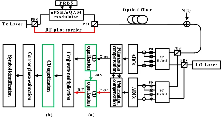
An example of a complete single polarization coherent system is schematically shown in Fig. 1 including an optical RF signal tone for eliminating the phase noise. We will consider an FDE filter or a maximum likelihood sequence estimation (MLSE) filter for the chromatic dispersion compensation and carrier phase extraction using the normalized least mean square (NLMS) method [27]. We note that in this configuration the FDE and the FD-FIR filters give the same bit-error-rate (BER) performance [21]. The FDE, rather than the FD-FIR filter, is selected as commonly used in most practical system demonstrations at this time. As indicated in Fig. 1, we consider two situations, namely 1) CD compensation takes place prior to the RF based phase noise compensation and 2) CD compensation takes place after the RF based phase noise compensation. In the simulations, we will not consider the use of an Rx based RF pilot tone extraction [25] which in principle allows the use of two polarization states for signal transmission.
Some earlier works for PSK/QAM systems have considered an RF pilot tone transmitted in the orthogonal polarization relative to the signal [24,25]. This removes any limitations for the RF bandwidth and significantly simplifies the receiver implementation which would be more difficult to perform when including filtering to recover the RF pilot tone. This represents a limiting (best possible) situation for the elimination of phase noise and is the RF tone implementation considered in this paper. The RF tone transmitted in the same polarization state as the signal is significant to consider in future practical PSK/QAM system implementations
We note that for OFDM systems it is more natural to have the RF pilot tone as one tone in the center of the OFDM signal grid since each OFDM tone is demodulated separately [28].
The principle of phase noise cancellation by an RF pilot tone carrier is simple. Let the detected coherent signal field – in the ideal case without any influence of equalization enhanced phase noise - be represented as:
(
)
(
)
( ) ( ) exp ( ) ( ) ( )
s Tx LO
E t =A t ⋅ j φ t +φ t +m t (1)
where n-level PSK or QAM modulation is considered, i.e. A(t) is the modulated (real-valued) amplitude, φTx( )t is the phase noise from the transmitter, φLO( )t is the phase noise from the local oscillator (LO), and m(t) represents the phase modulation. The additive noise contribution from transmitter and local oscillator is a good approximation in our simplified model. The RF pilot tone in the ideal case is:
( ) exp( ( ( ) ( )))
RF Tx LO
E t = ⋅B jφ t +φ t (2)
where B is an arbitrary constant amplitude, and the conjugated signal operation that eliminates the phase noise is given (within the arbitrary amplitude constant, B) as:
#162022 - $15.00 USD Received 23 Jan 2012; revised 22 Mar 2012; accepted 27 Mar 2012; published 2 Apr 2012
( )
*
( ) ( ) exp( ( ))
s RF
E t ⋅E t = ⋅B A t ⋅ jm t (3)
In the simulations, we consider a QPSK system with a symbol frequency of 28 GS/s i.e. the single polarization system capacity is 56 Gb/s. We utilize the software tool from VPI [26] for the system simulations, and we evaluate the bit-error-rate versus optical signal-to-noise ratio (OSNR).
2.2 Phase noise analysis
It is relevant to discuss the total phase noise influence in the system. In this discussion we will consider the case where the fiber dispersion has a zero dispersion slope i.e. the dispersion is constant over the signal bandwidth. The inclusion of a non-zero dispersion slope will be commented on in the discussion in section 3 and will be the subject of future research efforts. Furthermore, we will in the first part of the discussion focus on the (fixed) FDE filter for CD equalization. In this configuration the EEPN scales linearly with the accumulated chromatic dispersion and the linewidth of the Tx or the LO laser. The laser that contributes to the generation of EEPN is the one where the laser phase noise interacts with a non-zero net-dispersion. In the reference situation without phase noise compensation (i.e. no RF pilot tone is transmitted and the complex multiplication stage in the Rx is omitted in Fig. 1) this means that the LO laser generates EEPN. This is also the case when the CD equalization takes place prior to the complex multiplication. When the CD equalization is performed after the complex multiplication, the LO laser phase noise is cancelled, and it does not interact with the CD equalization stage. Accordingly, the LO laser does not generate EEPN. However, the Tx laser phase noise interacts with the transmission fiber dispersion but does not interact with the CD equalization. Thus the Tx laser generates EEPN in this situation. The variance of the additional noise due to the EEPN can be expressed as follows, see e.g [13]:
2 2
2 2
A
EEPN EE s
S
D L f
f T
c T
πλ
σ = ⋅ ⋅ ⋅ ∆ ≡ π∆ ⋅ (4)
where index A = LO or A = Tx shows the laser that contributes to EEPN, λ is the central
wavelength of the transmitted optical carrier wave, c is the light speed in vacuum, D is the chromatic dispersion coefficient of the transmission fiber, L is the transmission fiber length,
∆fLO is the 3-dB linewidth of the LO laser, ∆fEE is the 3 dB linewidth associated with EEPN and Ts is the symbol period of the transmission system. This enables a definition of the effective
intermediate frequency (IF) linewidth [21] - which defines the phase noise influence in the receiver:
2
2 2 2
2 2
Eff Tx LO EEPN
Eff Tx LO EE
S s
f f f f
T T
σ
σ σ σ
π π
+ +
∆ ≈ ≡ = ∆ + ∆ + ∆ (5)
where ∆fTx is the 3-dB transmitter laser linewidth, 2
2 Tx fTx TS
σ = π∆ ⋅ is the transmitter laser phase noise variance and 2
2
LO fLO TS
σ = π∆ ⋅ is the LO laser phase noise variance. Equation (5) implies that correlation between the LO and EEPN phase noise contributions can be neglected which is a valid approximation for a normal transmission fiber for very short (few km) or longer distances (above the order of 80 km) [21]. The BER-floor position which is defined from the phase noise influence is specified as (for an nPSK Rx) [29]:
2 1 log 2 NLMS floor Eff BER erfc n n π σ ≈ (6)
Normally, the phase noise to have a certain penalty in dB or a position of the resulting BER-floor is given in terms of a linewidth. If a reference value of ∆fEff,2 is specified for a 2PSK
#162022 - $15.00 USD Received 23 Jan 2012; revised 22 Mar 2012; accepted 27 Mar 2012; published 2 Apr 2012
system, then it follows that the required linewidth to have the same penalty for an nPSK system is given as ∆fEff,n≈n2∆fEff,2⁄4.
The discussion above is not applicable when the CD equalization is performed by an adaptive LMS filter. When no phase noise compensation takes place - or when the complex multiplication happens after the CD equalization – the adaptive filter coefficients are directly influenced by the received signal with phase noise. Therefore, the phase noise is expected to strongly influence the BER performance but no analytical description of an effective linewidth to describe the effect (see e.g. Equation (2)) is available. When the CD equalization takes place
after the complex multiplication, it is not influenced by the noise on the optical phase and, thus,
it may be expected that the resulting BER performance is very similar to the one using a fixed (FDE) filter.
Numerical examples will be considered in Section 3 of this paper.
n P S K /n Q A M m od u la tor
P R B S
T x L ase r
N (t)
L O L a ser
A D C s P ola riz at io n co m p en sa tio n C ar rie r p h as e e sti m at io n S ym b ol id en tif ic at io n
O p tica l fib e r
P B S
P B C
R F p ilot c ar r ier
P B S P B S X -p ol
Y -p ol
P D 9 0o
H y b rid
P D 9 0o
H y b rid
A D C s P ola riz at io n co m p en sa tio n R F C on ju ga te m u lti p lic at io n C D eq u ali za tio n
L M S
C D e q u ali za tio n
(b ) (a )
C D eq u ali za tio n
Fig. 1. Block diagram for single polarization nPSK/nQAM system using an optical RF pilot tone for phase noise correction (including red system parts). The chromatic dispersion (CD) equalization (indicated in green system blocks) takes place either before (case (a)) or after (case (b)) the conjugate multiplication. The green arrow indicated by LMS shows that the LMS filter tap weights are determined by the QPSK time signal and that the filtering of the RF tone path uses the same tap weights. N(t) shows the added optical noise which is used to measure the bit error rate (BER) as a function of optical signal-to-noise ratio (OSNR). Figure abbreviations: Tx – transmitter; PBS – polarizing beam splitter; RF – radio frequency; PRBS – pseudo random bit sequence ; LO – local oscillator; ADC – analogue to digital conversion; CD – chromatic dispersion.
3. Simulation results and discussion
In the simulations, we consider a QPSK system with a symbol frequency of 28 GS/s, i.e. the single polarization system capacity is 56 Gb/s. One polarization state is used to transmit an RF carrier. We consider a normal single mode transmission fiber with dispersion coefficient D = 16 ps/nm/km and zero dispersion slope. The transmission distance L is 2000 km. We consider an intrinsic intermediate frequency 3 dB linewidth of ∆fIF = ∆fLO + ∆fTx = 4 MHz and three
cases where we have 1) ∆fTx = 4 MHz, ∆fLO = 0; 2) ∆fTx = ∆fLO = 2 MHz and 3) ∆fTx = 0, ∆fLO = 4 MHz. For cases 1) and 3) this gives an effective linewidth (Eq. (3)) ∆fEE = 160.8 MHz
whereas for case 2 we have ∆fEE = 82.4 MHz. We note that the adaptive LMS filter
implementation in the Rx must be done in such a way that the filtering of the RF tone path uses the same tap weights as the signal path (as is indicated in Fig. 1). The procedure for determination of the tap weights is described in [12]. We utilize the software tool from VPI
#162022 - $15.00 USD Received 23 Jan 2012; revised 22 Mar 2012; accepted 27 Mar 2012; published 2 Apr 2012
[image:6.612.126.488.218.409.2][26] for the system simulations, and we evaluate the bit-error-rate versus optical signal-to-noise ratio (OSNR).
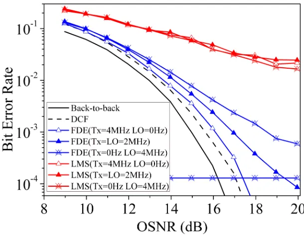
Fig. 2. BER for single polarization QPSK coherent system of Fig. 1 when the phase noise compensation is omitted. Results are for transmission distance of 2000 km. The 3 different intrinsic linewidth cases discussed in section 3 are indicated in the figure for the FDE and LMS CD equalization filters. The PRBS length is 216-1. Figure abbreviations: OSNR - optical
signal-to-noise ratio; Rx – receiver.
Figure 2 shows the reference system performance in the case where no phase noise compensation is performed for a single polarization QPSK system. The data display important trends for BER-values above the order of 10−4 where the simulation results are reliable. BER results are shown for the adaptive LMS CD compensation as well as using the FDE fixed filter. The 3 cases discussed in the previous paragraph are shown together with the theoretical prediction of the BER-floor position for case 3); the cases 1) and 2) have BER-floors (Eq. (6)) at 1.5·10−7 and 10−150 i.e. well below 10−4. The BER floor of case 3) which is 1.3·10−4 is shown on the figure. The figure shows for the LMS adaptive CD equalization that we have a strong influence of the laser phase noise with BER-values above 10−1 and that the result is the same for all three cases of distributing the phase noise between Tx and LO lasers. For the fixed FDE filter we have no phase noise influence from the Tx laser and increasing influence from the LO laser for cases 2)-3) when the LO laser linewidth is increased and EEPN increases accordingly. We have good agreement with the theoretically predicted error-rate-floor for case 3). The increasing EEPN influence for the FDE filter is as expected for case 2) and 3) [13,21,22,25]. For case 1) where EEPN from the Tx laser determines the phase noise performance we have a similar situation as when the CD equalization is performed in the transmitter with a FDE filter in the electrical domain [25].
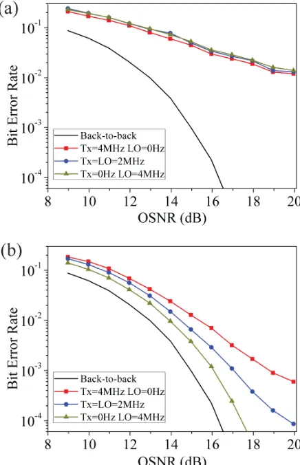
Figure 3 shows the system performance when RF pilot tone phase noise compensation is used for the adaptive LMS filter. Figure 3(a) is for the case when CD equalization is prior to the complex conjugation step in the Rx, whereas Fig. 3(b) is when the CD equalization is completed after the complex conjugation stage. When comparing to Fig. 2 it appears that the added phase noise compensation gives only a small improvement in BER performance in Fig. 3(a). Again the result is the same for all cases 1)-3). This is attributed to the fact that the
#162022 - $15.00 USD Received 23 Jan 2012; revised 22 Mar 2012; accepted 27 Mar 2012; published 2 Apr 2012
[image:7.612.150.455.102.338.2]adaptive filter update of weighting coefficients takes place when no phase noise compensation occurs. In Fig. 3(b) we have a significant improvement in BER performance compared to Fig. 3(a) which shows that the adaptive update of coefficients is much more efficient in a situation where the phase noise is eliminated as efficiently as possible. It is clear that residual EEPN from the Tx laser influences the BER performance.
Fig. 3. BER for single polarization QPSK coherent system of Fig. 1 when an adaptive LMS filter is used for CD equalization. Figure 3(a) is for CD equalization prior to phase noise compensation and Fig. 3(b) is for CD equalization after phase noise compensation. Results are for a transmission distance of 2000 km. The 3 different intrinsic linewidth cases discussed in section 3 are indicated in the figure. The PRBS length is 216-1. Figure abbreviations: OSNR - optical signal-to-noise ratio; Rx – receiver.
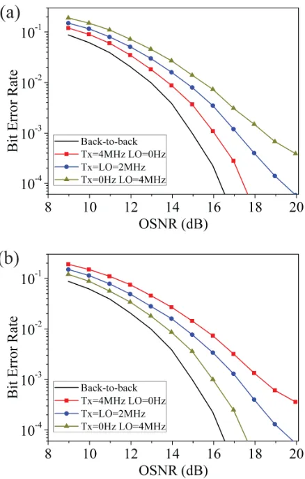
Figure 4(a) and Fig. 4(b) show the BER results for the FDE filter in the same format as Fig. 3 for the LMS filter. When comparing to Fig. 2, it appears that the added phase noise compensation gives only a small improvement in BER performance in Fig. 4(a) and the EEPN - which cannot be fully phase noise compensated - is caused by the LO laser. This is related to the fact (discussed in more details in the beginning of Section 2.2) that the LO laser noise interacts with CD compensation module which introduces a “wrong” dispersion distortion to the LO. Thus, the conjugate multiplication affects the dispersion distorted LO, while the situation with transmitter signal is exactly opposite – the CD compensation module neutralizes the CD introduced by the whole transmission link. In Fig. 4(b) we have an identical behavior as in Fig. 4(a) with the only difference that the EEPN which cannot be fully compensated is on the
#162022 - $15.00 USD Received 23 Jan 2012; revised 22 Mar 2012; accepted 27 Mar 2012; published 2 Apr 2012
[image:8.612.192.410.139.477.2]Tx laser. We observe that the LMS CD equalization filter gives a slight penalty compared to the FDE CD equalization filter when the complex multiplication is prior to the CD equalization.
[image:9.612.195.414.252.596.2]It is noted that the CD equalization using the fixed FDE (or FD-FIR) filter is ideal when the dispersion slope of the transmission fiber is zero (as considered in this paper). In a situation with non-zero dispersion slope this is not the case, and adaptive LMS filtering after complex multiplication to remove the phase noise should be expected to give better BER performance than FDE (or FD-FIR) filtering. When it comes to the update of CD equalization filter weights in the situation with non-zero dispersion slope then this appears major modifications for the FD-FIR filter (see [7,8,21]) whereas it is straightforward to update the filter frequency response for the FDE filter [9,10,21]. For the LMS filter, this is a straightforward and automated part of the adaptive filter optimization. The required number of significant taps for a specified fiber length for the FD-FIR filter and the required FFT size for the FDE filter needs careful consideration. The current discussion is important for practical systems and it should be quantified by further simulation studies.
Fig. 4. BER for single polarization QPSK coherent system of Fig. 1 when a fixed FDE filter is used for CD equalization. Figure 3(a) is for CD equalization prior to phase noise compensation and Fig. 3(b) is for CD equalization after phase noise compensation. Results are for a transmission distance of 2000 km. The 3 different intrinsic linewidth cases discussed in section 3 are indicated in the figure. The PRBS length is 216-1. Figure abbreviations: OSNR - optical
signal-to-noise ratio; Rx – receiver.
#162022 - $15.00 USD Received 23 Jan 2012; revised 22 Mar 2012; accepted 27 Mar 2012; published 2 Apr 2012
4. Conclusions
We have considered coherent systems with post-compensation in the Rx for transmission fibers with zero dispersion slope. In this type of Rx, the RF pilot carrier can be used to mitigate the phase noise influence in n-level PSK and QAM systems, and a discrete type filter can be used to compensate for the chromatic dispersion influence. The system phase noise performance – for instance specified in terms of bit-error-rate (BER) versus optical signal-to-noise-ratio (OSNR) - is influenced by the implementation of a RF pilot carrier to accomplish phase noise compensation through complex multiplication in combination with discrete filters to compensate for the chromatic dispersion.
We have performed a detailed study comparing two filters for the CD compensation, namely the frequency domain equalizer (FDE) filter and the adaptive least-mean-square (LMS) filter. When considering the LMS filter, we find (as a major new result from the simulations) that the system is influenced by equalization enhanced phase noise which originates from interaction of the intrinsic laser phase noise and the net CD. This means that using CD equalization prior to phase noise compensation (through complex multiplication) gives a resulting EEPN from the LO laser, whereas using CD equalization after the phase noise compensation gives no EEPN from the LO laser. However, since the CD equalizer does neither interact with the Tx or LO laser phase noise the the net CD from the transmission fiber provides an EEPN influence from the Tx laser. Thus, the FDE filter position relative to the RF carrier phase noise compensation provides a possibility for choosing whether the EEPN from the Tx or the LO laser influences the system quality.
The LMS filter works very inefficiently when placed prior to the RF phase noise compensation stage of the Rx, whereas it gives almost the same performance as the FDE filter when placed after the RF phase noise compensation stage.
#162022 - $15.00 USD Received 23 Jan 2012; revised 22 Mar 2012; accepted 27 Mar 2012; published 2 Apr 2012