Dynamic Performance and Effectiveness of
Voltage Disturbances on the Improvement of
Power Quality for Grid-Connected DFIG
System Based Wind Turbines
Shazly A. Mohamed
1*and Montaser Abd El Sattar
21Department of Electrical Engineering, Faculty of Engineering, South Valley University, Qena, Egypt 2
Department of Electrical and Computer Engineering, High Institute of Engineering and Technology, El-Minia, Egypt
[email protected] [email protected]
Abstract- Power quality (PQ) is renowned as any power
problem manifested as a non-standard frequency, current & voltage that cause failure of end customer apparatus. The wind utilization, generation & its penetration in electrical grid are increasing widespread. One of the main problems in wind is the connection to the network. If the wind is inserted to grid generally controls the voltage disturbances on the system power quality, variation of voltage is the almost prevalent type of disturbance which affects stability and the quality of power for grid-connected wind energy system. This paper investigates the two widespread types of voltage variations like voltage sag and swell, which can occur when large amount of wind system is connected to grid. Also this article studies the response and performance at faults of a wind turbines inserted to distribution systems. In this work, a wind turbine with DFIG system is simulated by using MATLAB/Simulink program. The simulated model is subjected to disturbances which define as; voltages (sag and swell). The results of simulation show that, voltage sag & swell lead to mal-operation as well as shut-down of entire system, so, deteriorating the enhancement of power quality for the utility grid.
Keywords: Voltage disturbances, Wind turbines, Power quality problems, DFIG system.
I.INTRODUCTION
Traditionally, the electrical grid has been prepared to integrate different types of conventional generation plants such as: gas, hydro and nuclear etc., and with increased population and manufacturing development, there is more demand of energy. To confront this large and increasing energy demand, it becomes necessary for the possible sources embracing the renewable energy like wind system
[1]. PQ is a big interest to the grid operators particularly when large wind is inserted to the electrical grid which, at rated frequency means to keep voltage/current waveforms is sinusoidal.
A wind farm is a set of wind turbines in the same site and used for the generation of wind system. Installing different turbines in groups at a location leads to
large-scale utilization of wind. This has operation, maintenance and economic features. Wind system is neat and abundant resource of energy; so, it plays a prevalent role in adding neat and non-polluting energy to the electrical grid.
Actually, wind system can effectively contend with other conventional resources of energy in the market [2]. Thus, as contend by Rini Ann Jerin and et al. [3], wind energy is starting to contend with other conventional resources of renewable energy. Utilize clean energy like wind using to generate electricity reduces the dependency on fossil fuels.
Power quality is one of the important roles in electrical system due to increasing penetration of renewable energy sources and it is extremely affected by the working of a transmission and distribution grid [4]. One of the modest techniques of a wind operation is to use the DFIG linked directly to the grid. The main issues of the power quality such as; voltage sag and swell in low voltage distribution systems & on the transmission side due to sensitive loads. Thus, voltage at the point of common coupling (PCC) should be maintained within a specific limit to keep the power quality required by consumers [5]-[7].
II.DFIGTECHNOLOGY
Wind farm employ a doubly fed induction generator (DFIG) which consists of a wound rotor & an AC/DC/AC insulated-gate bipolar transistor based on pulse width modulation converter. The stator winding of DFIG is directly linked into the grid, while the rotor is fed at variable frequency across the power electronic converter model. The operation of DFIG is depend on the principle of induction generator. By regulating the converter’s parameters, it is bearable to control the real and reactive power fed to the grid independently of the generators turning speed, giving it a distinct merit over other conventional power generators. The DFIG technology is usually used in wind turbines; this is an important wind conversion system having variable-speed ability. These machines are also famous as wound rotors or slip-ring IG
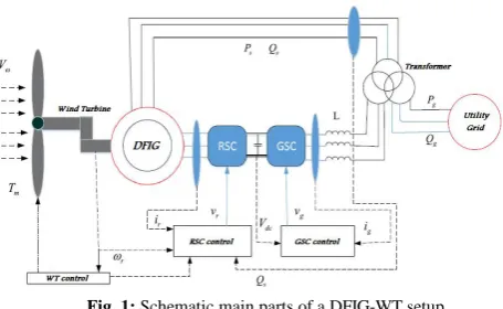
in different ranges of power (1.5-6 MW). Fig. (1) shows schematic main parts of a DFIG-WT setup.
The wind turbine is a set of mechanical and electrical parts, the DFIG system, (RSC) rotor-side converter, DC-link, (GSC) grid-side converter and the control unit. The main task of the GSC is to regulate the bus voltage Vdc.
The task of the RSC is to control the speed to realize power from the wind across an extent of wind speeds. There are many types of wind generator, but this paper focus about DFIG unit. Generally, features of the DFIG based wind turbine can be brief as follows: control of power factor can be executed at lower cost, improvement of PQ, reduced acoustic noise and another advantage of DFIG system has top performance through a voltage sag, disturbance situation &transient time[9],[10].
Fig. 1: Schematic main parts of a DFIG-WT setup
1. Turbine constant speed
For constant WT speed, the generator is inserted to the grid which stator is injected and will constantly operate at fixed speed anyhow rapidly the wind strikes. Fixed WT's speed is basically used induction generator for generation and it is stall regulated. The rotor windings three-phase is directly injected into the grid, while the stator supplies excitation to the machine. The shaft rotation speed can be studied in terms of frequency of electrical power supply (f) and pole-pairs (p) [11]-[13].
(1)
The second parameter used in the analysis of induction generator is the slip that is define as the difference among the synchronous speed & the rotor speed illustrated as a percentage of the synchronous speed which calculated as:
(2)
Two slip modes, (+ve) for motoring and (-ve) for generating. So, wind with induction generator can supply power to the grid when the speed, N𝑟 overtakes the synchronous speed, N𝑠.
2. Turbine variable speed
The machine is allowed to be driven at varying speed with the wind. For this purpose a converter model is used to switch the AC to DC & finally to the grid, AC variable speed WTs can be stall, pitch regulated and active-stall types. In stall, the blades of the WT are sure fixed to the
hub at a particular angle and this technique is simple, cheap and robust. This can be carried out by varying the pitch of the blade or direction & changes its aerodynamic competence. Otherwise, in active-stall, the rotation of the rotor is executed by pitching the blades back to a deeper stall [12].
III.VOLTAGE VARIATIONS IN WIND POWER
The variations of voltage is directly associated to active and reactive power variations owing to the fluctuations in the WT due to wind and are described as the changes in the root mean square value of the supply voltage through a short time ranging among micro-seconds to few minutes
[13]. For grid-connected wind, the parent variations of voltage can be in the forms such as: voltage sag or swell, transient, harmonics & short interruptions. Fig. (2) shows a grid-connected WT configuration.
Fig. 2: A grid-connected WT representation
Apply Kirchhoff’s voltage law to Fig. 2 gives: (3)
Where: V1: Grid voltage, V2: Voltage at the WT.
r: Resistance of the grid and x: Reactance of the grid. When the wind turbine generates the power desired to meet the load demand and no current drawn from grid. At this status, V1 must be equal to V2 according to eq. (3).
So, when the WT produces more power than demanded, then, V1 will be less than V2. Similarly, when the WT
creates lower power than demanded, then, the difference among the load and turbines generated power shall be supplied to the grid, the current drawn will pass through the impedance, thus, grid voltage shall be greater than at the PCC. So, the short circuit power (Ssc) in the wind
connected point can be computed as follows:
(4)
Where: Z, Impedance of the grid (Z = r + J x).
terms of real power (Pw), reactive power (Qw), impedance
(Z) and the nominal phase voltage of the grid [14].
(5)
Where: Vn, Nominal voltage of the grid.
Among all forms of variations; voltage sag & swell are widespread. Therefore, they are the main focused in this study as follows:
A. Voltage Sag
Voltage sag means a short sudden reducing in the potential of the grid and can occurs at any instant of the time usually ranging among 10 to 90 % of its nominal value followed by a fast return which typically lasts for interval from one-half cycle to a minute and may affect phase/amplitude [15]. Generally, voltage sags are caused by weather and utility equipment, it associated as a result of faults, electric heaters turning on and starting of large motors. The decrease of relative voltage change ΔVd at
point of interconnection for the wind can be presented in terms of the change factor of voltage (Kv), the apparent
power of the WT (Sr) and the short circuit power of the
grid (Ssc). The allowable voltage sags limiting rate is ≤ 3
percentage [16].
(6)
Where: ΔVd, Voltage dip change.
Kv: Sudden voltage reduction factor.
Sr: Rated apparent of the wind.
B. Voltage Swell
Voltage swell means a short duration increase in the RMS value of the supply voltage which is among 110 and 180 %, at the fundamental frequency for time duration of 0.5-cycle to one minute. For grid-connected WT, voltage swell can occur owing to the inrush currents or shut down of large capacity of the WT's. One more resources of voltage swell encompass grid lightning, fault on other phase and improper tuning of substations [17].
The increase of relative voltage change, ΔVr at point of
interconnection for the wind turbine can be expressed as a function of turbine’s maximum power (𝑆𝑚𝑎𝑥), grid impedances (Z) of the grid, the phase difference ( ) and nominal voltage of the grid. The limiting voltage swell acceptable is < 2 percentage [16]-[18]. Fig. (3) showsan RMS depiction of voltage sag and swell.
(7)
Where: ΔVr, Voltage rise change.
Smax: Turbine maximum power.
Fig. 3: Depiction of voltage sag and swell
IV. Simulation & Experimental Setup
The system is simulated based MATLAB software that illustrates in Fig. (4) is a 3-phase source connected to a 9 MW wind turbines based DFIG, consists of (6*1.5MW) each WT at 0.92 power factor that inserted to distribution system with a 25kV and exports power to a 120kV grid across 30Km/25kV feeder. At B25, factory of 2*106VA, 2.3kV with 1.68MW induction motor load, p.f of 0.94 lagging and a resistive load of 0.2MW. Also 0.5MW of a resistive load is injected on the 575V bus. A protection system is integrated to WT & motor load that observes the parameters such as: machine speed, current and voltage. This study applied to investigate the steady-state and dynamic response of a WF based DFIG technology. The system parameters are listed in Appendix.Fig. 4: Wind farm based on DFIG simulated model
V. Results and Discussion
The voltage variation and dynamic response of a wind farm based on the DFIG system is tested as follows:
Case study (1): Effect of voltage sag
of motor as shown in Fig. 5-c decreases gradually as soon as the protection unit drives the factory. Fig. 5-d depicts the WT maintains on real power generating at 1.85MW. So, at B25, 1.35MW real power is transmitted to the grid after the factory has tripped as shown in Fig. 5-e.
(a)
(b)
(c)
(d)
(e)
Fig. 5: Voltage sag based VAR regulation mode
Case study (2): Effect of voltage swell
In this case, a 0.2pu voltage swell lasting 0.52s is set to the 120kV utility grid to occur at the simulation time of 8s and the WT control adjusts to VAR regulation mode.
The simulation results of wind farm in VAR regulation mode are shown in Fig. (6) at 9m/s constant wind speed. Notice that, from Fig. 6 (a-e) a voltage swell for period of 0.52s exceeding the threshold limit trips the factory 0.22s after it is measured, the speed of motor starts decreasing gradually.
(a)
(b)
(c)
(d)
(e)
Fig. 6: Voltage swell based VAR regulation mode
Case study (3): WT response to variation in wind speed
to simulation. At t=5s, the active power generated starts increasing simply with each other with the turbine speed to arrive its rated value of 9MW in about 15s. During this time period the turbine speed increases among 0.82pu to 1.24pu. The pitch angle is (0) deg., the turbine working point follows the red curve of the wind characteristics up to point D as depicted in Fig. (7). The DFIG is controlled to follow the curve (ABCD) in wind characteristics. Turbine speed optimization is obtained at points (B&C). In this study, the rotor is operate at sub-synchronous for speeds less than 10m/s and it is operating at a super-synchronous for higher speeds of the wind. The output power of the turbine is presented for different speeds ranging among 5m/s to 16.2m/s.
Fig. 7: Wind characteristics based DFIG
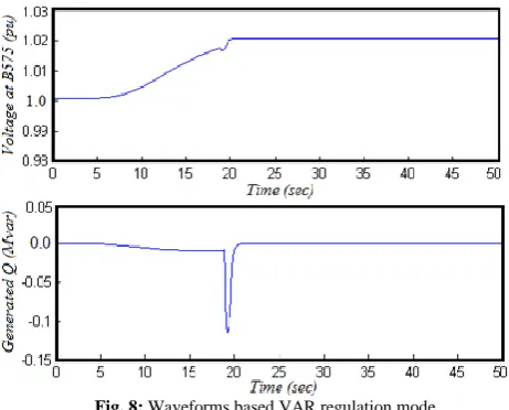
Also, observe that, voltage & reactive power generated that is controlled to maintain a one pu voltage. The wind absorbs 0.7 MVAR to control voltage at one pu. If you change the mode to VAR regulation based on the reactive power generated Qref regulate to zero, the voltage will
increases to 1.3 pu if the WT produces its nominal power at unity power factor. Fig. (8) illustrates the wind farm waveforms based on VAR regulation mode.
Fig. 8: Waveforms based VAR regulation mode
Case study (4): Effect of a single fault
In this scenario, observe the effect of a single phase fault happen on 25kV system that applied at t=5s on phase (A)
at B25. If the VAR regulation mode is applied with Qref
regulate to 0, the voltage falls to 0.74 pu and the under-voltage trips the WF. Observe that, the turbine speed will increase. At t=40s the pitch angle initiates to increase to limit the speed. Fig. (9) depicts the simulation results of wind farm waveforms during fault at B25 based on VAR regulation mode.
Fig. 9: Simulation results during fault based VAR regulation mode
CONCLUSION
APPENDIX
The system parameters applied are given as follows:
Grid Voltage:
3-phase, 25 kV, 60 Hz.
Generator Parameters:
Power rated: 6*1.5 MW at 0.92 PF, 575 V, 60 Hz. Stator resistance & reactance = Rs= 0.014 and Ls = 0.2 pu
Rotor resistance & reactance = Rr= 0.01 and Lr = 0.16 pu
Magnetizing inductance Lm = 5 pu
Parameters of WT
Nominal mechanical power: 6*1.5MW
Controller gain of pitch angle [Kp] = 500 with (deg) = 45
Converter parameters:
Maximum power = 0.52 pu
Grid-side [L R] = [0.15 0.15/100] pu
IGBT with 3 arms, 6 pulse and sample time 5 μs. Nominal DC-bus voltage = 1200 V
Nominal DC-bus capacitor = 6*10000e-6 F
Control Parameters:
Reference voltage Vref = 1 pu
Gains of grid voltage [Kp Ki] = [1.32 300]
Generated reactive power Qref (pu) = 0 pu
Gains of reactive power [Kp Ki] = [0.1 5]
Load Parameters:
Plant with induction machine load 1.68 MW at 0.94 PF, 2300 V, 60 Hz with resistive load = 200 Kw
Load = 500 kW inserted on the 575 V bus.
REFERENCES
[1] M. Nazir, Q. Wu, M. Li, Symmetrical short-circuit parameters comparison of DFIG–WT, International Journal of Electrical and Computer Engineering Systems, 8: 77-83, 2017.
[2] Ch. Subramanian, D. Casadei, A. Tani, C, Rossi, Modeling and Simulation of Grid Connected Wind Energy Conversion System Based on a Doubly Fed Induction Generator (DFIG), International Journal of Electrical Energy, 2: 161-166, 2014.
[3] R. Jerin, N. Prabaharan, K. Palanismy, S. Umashankar, FRT Capability in DFIG based wind turbines using DVR with Combined Feed-Forward and Feed-Back Control,Energy Procedia, 138: 1184-1189, 2017.
[4] S. Mohod, M. Aware, A STATCOM Control Scheme for Grid Connected Wind Energy System for Power Quality Improvement, IEEE
Systems Journal, 4: 346-352, 2010.
[5] S. Valentine, Understanding the variability of wind power costs,
Renewable and Sustainable Energy Reviews, 15: 3632– 3639, 2011.
[6] Shazly Abdo Mohamed and Salma AbdelAal Shaaban, “Impact of
Wind Farm with Static Compensator under Grid Faults”, IEEE Twentieth International Middle East Power Systems Conference (MEPCON), Cairo University, Egypt, Dec. 2018.
[7] Y. Ceyhun, et al, Power Quality Measurement and Evaluation of a Wind Farm Connected to Distribution Grid, Procedia - Social and Behavioral Sciences, 195: 2370 – 2375, 2015.
[8]D. Gaona, E. Goyti, O. Lara, Fault Ride-Through Improvement of DFIG-WT by Integrating a Two-Degrees-of-Freedom Internal Model Control, IEEE Transactions on Industrial Electronics, 60 (3): 1133-1145, 2013.
[9] A. Khajeh, R. Ghazi, M. Abardeh, Implementation of the Maximum Power Point Tracking Algorithm on Indirect Matrix Converter Controlled DFIG wind Turbine, The 4th International Conference on Renewable Energy and Distributed Generation, Iran, Mashhad, 11-15, 2016.
[10] A. Safaei, S. Hosseinian, H. Abyaneh, Investigation and enhancement of SFCL impacts on DFIG‐based wind turbine during
fault and post‐fault, Int. Trans. Electrical Energy System, Wiley, 1-13. 2016.
[11] P. Pfister, Y. Perriard, Torque Measurement Methods for Very High Speed Synchronous Motors, Proceedings of International Conference on Electrical Machines, 1-5, 2008.
[12] B. Whitby, C. Ugalde-Loo, Performance of Pitch and Stall Regulated Tidal Stream Turbines, IEEE Transactions on Sustainable Energy, 5 (1), 64-72, 2014.
[13] N. Kadandani, Y. Maiwada, Impact of Voltage Sag and Swell on the Power Quality of Grid Connected Wind Power Plant, the International Journal of Engineering and Science (IJES), 4 (7), 56-64, 2015.
[14] Q. Zhong, Z. Ma, W. Ming, C. George, Grid-friendly wind power systems based on the synchronverter technology, Energy Conversion and Management journal, 89, 719–726, 2015.
[15] S. A. Mohammed, M. Abdel-Moamen, B. Hasanin, Analysis, Modeling and Simulation of Dynamic Voltage Restorer for Compensation of Voltage Quality Disturbances, International Journal of Control, Automation and System, 1 (2), 23-29, 2013.
[16] M. Thirupathia, P. Prasad, Analysis of Various Compensation Devices for Power Quality Improvement in Wind Energy System,
International Journal of Electrical Engineering & Technology (IJEET), 7 (3), 25–39, 2016.
[17] E. Babae, F. Shahir, S. Tabrizi, Compensation of Voltage Sags and Swells using Photovoltaic Source Based DVR., 2017 IEEE 14th International Conference on Electrical Engineering/Electronics, Computer, Telecommunications and Information Technology (ECTI-CON), 930-906, 2017.