International Journal of Science Engineering and Advance
Technology, IJSEAT, Vol 2, Issue 11, November - 2014
ISSN 2321-6905
www.ijseat.com
Page 712
Performance Improvement of IUPQC in Distribution
System under Abnormal Conditions Using FLC
E.DURGA PRASAD
SHEIK MAHABOOB SHARIFF
N.RAMA SURYA RAO
PG scholar, Dept of EEE, Assistant professor, Dept of EEE PG scholar, Dept of EEE,
Pragati Engineering College, Pragati Engineering College, Kakinada Institute of Engg.&Technology II
JNTUK, Surampalem, A. P. JNTUK, Surampalem, A. P. JNTUK, Surampalem, A. P.
Abstract: This paper proposes a new connection for a Interline Unified Power Quality Conditioner (IUPQC) to improve the power quality of two feeders in a distribution system. An IUPQC consists of a series voltage-source converter (VSC) and a shunt VSC both joined together by a common dc bus which is placed in between two different independent feeders to regulate the bus voltage of one of the feeders while regulating the voltage across a sensitive load in the other feeder. In the earlier case IUPQC is operated with VSC’s with Proportional plus Integral (PI) controller to mitigate harmonics& sags. The structure, control and capability of the IUPQC with Fuzzy Logic Controller (FLC) at Faults & Swells are discussed in this paper. The efficiency of the proposed configuration has been verified & compared with PI configuration through simulation studies using MATLAB/SIMULINK.
Keywords: Distribution system, Fuzzy Logic
Controller (FLC),Faults, Power Quality, Sensitive Load, Voltage Sag, Voltage Swell, Voltage-Source Converter (VSC), Total Harmonic Distortion (THD).
I.INTRODUCTION
Due to the usage of number of electronic components in industries, residences etc, where these devices need high quality energy to work properly & at the same time these are the most responsible for injection of voltage sags, swells, harmonics and other related disturbance in the distribution system. Voltage Source Converter based custom power devices are increasingly being used in custom-power applications for improving the power quality (PQ) of power distribution systems. Devices such as distribution static compensator (DSTATCOM) and dynamic voltage restorer (DVR) have already been discussed extensively in [1]. A DSTATCOM can compensate the distortion and unbalance due to symmetrical & asymmetrical faults in a load such that a balanced sinusoidal current flows through the feeder [2]. It can also regulate the voltage of a
distribution bus[3], [4]. A DVR can compensate the voltage sag/swell and distortion in the supply side
voltage such that the voltage across a
sensitive/critical load terminal is perfectly
regulated[5], [6]. An Interline unified power-quality conditioner (IUPQC) can perform the functions of both DSTATCOM and DVR [7], [8].The IUPQC consists of two voltage-source converters (VSCs) that are connected to a common dc bus. One of the VSCs is connected in series with a distribution feeder, while the other one is connected in shunt with the same feeder.
In [9], a configuration called IDVR has been discussed in which two DVRs are connected in series with two separate adjacent feeders. The dc buses of the DVRs are connected together. The IDVR absorbs real power from one feeder and maintains the dc link voltage to mitigate 90% (about 0.1 p.u.) voltage sag in the other feeder with balanced loads connected in the distribution system. It is also possible to connect two shunt VSCs to different feeders through a common dc link. The IUPQC consists of two voltage-source converters (VSCs) that are connected to a common dc bus.
International Journal of Science Engineering and Advance
Technology, IJSEAT, Vol 2, Issue 11, November - 2014
ISSN 2321-6905
www.ijseat.com
Page 713
absorb power from one feeder (sayFeeder-1) to Hold Vt2 constant in case of a sag in the voltage Vs2.This can be accomplished as the two VSC’s are supplied by a common dc capacitor. The dc capacitor voltage control has been discussed here along with voltage reference generation strategy. Also, the limits of achievable performance have been computed. The performance of the IUPQC has been evaluated
through simulation studies using
MATLAB/SIMULINK.
II. STRUCTURE AND CONTROL
The IUPQC consists of two VSCs (VSC-1 and VSC-2) that are connected back to back through a common energy storage dc capacitor Cdc. Let us
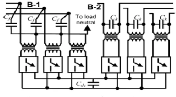
assume that the VSC-1 is connected in shunt to Feeder-1 while the VSC-2 is connected in series with Feeder-2.An IUPQC connected to a distribution system is shown in Fig.1.
Figure1. IUPQC connected in distribution system
In this figure 1, the feeder impedances are denoted by the Pairs (Rs1, Ls1) and (Rs2, Ls2). It can be seen that the two feeders supply the loads L-1 and L-2. The load L-1 is assumed to have two separate components—an unbalanced part (L-11) and a non-linear part (L-12).The currents drawn by these two loads are denoted byIt11and It22 respectively. It is assumed that the load L-2 is a sensitive load that requires uninterrupted and regulated voltage. The shunt VSC (VSC-1) is connected to bus B-1 at the end of Feeder-1[3], [4], while the series VSC (VSC-2) is connected at bus B-2 at the end of Feeder-2 [5], [6]. The voltages of buses B-1 and B2 and across the sensitive load terminal are denoted by Vt1 and Vt2 respectively. In order to attain these aims, the shunt VSC-1 is operated as a voltage controller while the series VSC-2 regulates the bus voltage Vt2across the sensitive load [1]. The length of Feeder-1 is arbitrarily chosen to be twice that of Feeder-2.The complete structure of a three-phase IUPQC with two such VSCs is shown in Figure.2
Figure 2.Complete structure of an IUPQC
The secondary (distribution) sides of the shunt-connected transformers (VSC-1) are shunt-connected in star with the neutral point being connected to the load neutral. The secondary winding of the
series-connected transformers (VSC-2) are directly
connected in series with the bus B-2 and load L-2.The schematic structure of a VSC is shown in Fig.4. Each of the two VSCs is realized by Three H-bridge inverters [10],[11].
Figure 3. Schematic structure of VSC
In this structure, each switch represents a power semiconductor device (e.g., IGBT) and an anti-parallel diode as shown in Fig.3. All the inverters are supplied from a common single dc capacitor Cdc and each inverter has a transformer connected at its output.
A)IUPQC Power System: Block diagram &
International Journal of Science Engineering and Advance
Technology, IJSEAT, Vol 2, Issue 11, November - 2014
ISSN 2321-6905
www.ijseat.com
Page 714
can be generated within the 3-Φ grid supply. Here feeder-1 is taken in bottom side & feeder-2 is taken at top.
Fig.4 Block Diagram of IUPQC power circuit
Fig.5 Simulation Diagram in MATLAB
B) Control Strategies: The two control strategies in this work have been investigated are Proportional Integral (PI) controller and Fuzzy Logic controller (FLC).
i) Proportional-Integral (PI) controller: The main goal of the controller is to maintain constant voltage
magnitude at sensitive load during supply
disturbances. This control method is based on comparing source and load voltage. The three phase voltage is transformed to dqo, using park transformation. After converting the voltage is constant with d-voltage is 1 in p.u and q-voltage is 0
in p.u under the normal and balanced condition but varies under abnormal condition. After comparison d-voltage and q-d-voltage with the desired d-voltage, the difference in voltage is enhanced by PI controller, after it go through dqo to abc transformation to convert into abc component which is the main signal to generate switching pulses of voltage source PWM inverter. The significant role of controller is to detect the voltage sag, swell, harmonics & faults, inject voltage deviation and turn off inverter, when voltage sag event in the system is removed. Fig.6 represents the PI controller placed in feed back path.
The input of the controller come from the Sensitive load voltage, VSL measured by three-phase V-I measurement at Sensitive Load in p.u. VSL is then transformed in dq term. The voltage sag is detected by measuring the error between the dq voltage and the reference values. Such error is processed by a PI controller. The d-reference is set to rated voltage as unity in p.u while q-reference is set to zero.
Fig.6 PI-Controller
ii) Fuzzy Logic controller (FLC): FL controllers are a smart choice when exact mathematical formulations are tedious. The construction of the rules requires a detailed understanding of the system to be controlled. Fig.7. shows the FL controller which can be characterized as follows: 7 linguistic variables for Error, 7 linguistic variables for Derivative Error are two inputs and 7 linguistic variables for output. Triangular membership functions for Error & Derivative error in terms of voltages and triangular membership functions for output variables are considered. A rule base of 49 rules is selected to establish the fuzzy controller [14]. With the use of Mamdani’s implication and with de-fuzzification by a centroid method, the FL controller provides the switching function to carry out best control action and each rule expresses an operating condition in the
International Journal of Science Engineering and Advance
Technology, IJSEAT, Vol 2, Issue 11, November - 2014
ISSN 2321-6905
www.ijseat.com
Page 715
Fig.7 Fuzzy logic Controller
In this paper, the error in terms of voltage(Vd) and the derivative of error in terms of voltage (ΔVd) are considered as the inputs of the first FL controller and the the error in terms of voltage (Vq)and the derivative of error in terms of voltage (ΔVq) as the inputs of the second FL controller. The reference voltages for the voltage regulator are the voltages Vdref and Vqref. The FL controller consists of 7
linguistic variables from Error which are as negative big (NB), negative medium (NM), negative small (NS), zero (ZE), positive small (PS), positive medium (PM) and positive big (PB).For derivative error are same 7 linguistic variables as negative big (NB), negative medium (NM), negative small (NS), zero (ZE), positive small (PS), positive medium (PM) and positive big (PB).The membership functions of the inputs are illustrated in Fig 8 and Fig 9.
Fig.8 Membership Function of Error
In de-fuzzification process, there are 7 linguistic variables through which Error and Error-rate are defined by these linguistic variables such as negative big (NB), negative medium (NM), negative small (NS), zero (ZE), positive small (PS), positive medium (PM) and positive big (PB) characterized by triangular membership functions Fig. 10. shows each parameter in membership function of Output .
Fig.9 Membership Function of derivative error
Fig.10 Membership Function of output
iii) PWM voltage control in Inverter: Ac loads may require constant or adjustable voltage at their input terminals. When inverters feed such loads, it is essential that output voltage of the inverters is so controlled as to fulfill the requirement of ac loads. An ac load may require a constant input voltage through different levels. For such load, any variations in the dc input voltage must be suitably compensated in order to maintain a constant voltage at the load terminals at the desired level. There are three possible methods of external control of ac output voltage obtained from inverter output terminals. These methods are: a. Ac voltage control
b. Series –Inverter control c. Shunt -Inverter control
d. Pulse Width Modulation control
In Pulse Width Modulation Control method, a fixed dc input voltage is given to the inverter and a controller ac output voltage is obtained by adjusting the on and off period of the inverter components. This is the most popular method controlling the output voltage and this method is termed as Pulse Width Modulation (PWM) control.
International Journal of Science Engineering and Advance
Technology, IJSEAT, Vol 2, Issue 11, November - 2014
ISSN 2321-6905
www.ijseat.com
Page 716
Different PWM techniques are as under
a) Single–pulse modulation b) Multiple–pulse modulation & c) Sinusoidal pulse modulation
In PWM inverters, forced commutation is
essential. The three PWM techniques listed above differ from each other in the harmonic content in their respective output voltage. Thus, choice of a particular PWM technique depends upon the permissible harmonic content in the inverter output voltages. The converter output voltage can be controlled using various control techniques. Pulse Width Modulation (PWM) techniques can be designed for the lowest harmonic content. It should be mentioned that these techniques require large number of switching per cycle leading to higher converter losses. Therefore, PWM techniques are currently considered unpractical for high voltage applications. However, it is expected that recent developments on power electronic switches will allow practical use of PWM controls on such applications in the near future. Due to their simplicity many authors, i.e. have used PWM control techniques in their IUPFC studies.
When sinusoidal PWM technique is applied to turn on and turn off signals for GTOs are generated comparing a sinusoidal reference signal Vr of amplitude Ar with a saw tooth carrier waveform Vc
of amplitude Ac. The frequency of the saw tooth waveform establishes the frequency at which GTOs are switched..The fundamental frequency of the converter output voltage is determined by the frequency of the reference signal. Controlling the amplitude of the reference signal controls the width of the pulses. The amplitude modulation index is defined as ratio of Ar to Ac.
m = Ar/Ac.
For m≤1 the peak magnitude of the fundamental frequency component of the converter
Output voltage can be expressed as V=m Vdc/2.
System Parameters Values
System fundamental frequency
50Hz
Voltage source(vs1) 415(L-L,rms),Phase angle 0o
Voltage source(vs2) 415(L-L,rms),Phase angle 0o
Feeder-1(R1+jX1) Impedence : (6+j36)Ω
Feeder-2 (R2+jX2) Impedence : (3+j18) Ω
Load L11
Unbalanced RL component
Phase-A : (24+j60) Ω Phase-B : (36+j78) Ω Phase-C: (48+j94) Ω Load L12 Non- Linear
component
3-phase diode rectifier supplies a load of (10+j9.45) Ω Balanced load L2
impedence
P=2.5KW,Q=30Var.
Table 1. System Parameters
III. System Description
An IUPQC connected to a distribution system is shown in Fig.1. In this figure, the feeder impedances are denoted by the pairs (R1,X1) and (R2,X2) . It can
be seen that the two feeders supply the loads L-1 and L-2. The load L-1 is assumed to have two separate components—an unbalanced part (L-11) and a non-linear part (L-12). The currents drawn by these two loads are denoted by iL11and iL12 , respectively. We
further assume that the load L-2 is a sensitive load that requires un-interrupted and regulated voltage. The series VSC (VSC-1) is connected to bus B-1 at the end of Feeder-1, while the shunt VSC (VSC-2) is connected at bus B-2 at the end of Feeder-2. The voltages of buses B-1 and B-2 and across the sensitive load terminal are denoted by Vt1, Vt2, and
Vt3, respectively. The aim of the IUPQC is two-fold
to protect the sensitive load L-2 from the disturbances occurring in the system by regulating the voltage; to regulate the bus B-1 voltage against sag/swell and or disturbances in the system. In order to attain these aims, the shunt VSC-2 is operated as a voltage controller while the series VSC-1 regulates the voltage V across the sensitive load. The system parameters used in the study are given in Table 1. The length of Feeder-1 is arbitrarily chosen to be twice that of Feeder-2.
IV. IUPQC Operation
As we know that VSC-2 like DSTATCOM injects current into the feeder-2 whereas VSC-1like DVR regulates voltage in the feeder-1.Both gets supply from opposite feeder when they are operating for their corresponding feeders through a D.C link capacitor. PI Controller or FLC controllers are used to generate the control signals to PWM pulse generator which in turn helps to control the inverter operation. IUPQC is an interline UPQC connected between two 11KV/415 distribution feeders which can alone controls the feeder operation under abnormal conditions like Sag, Swell, Harmonics, Symmetrical & Asymmetrical faults. D.C link acts as a source to individual feeder connected VSC’s. Unbalanced resistive/ impedance load can be connected to feeder-1 along with a non-linear load, sensitive uncontrolled non-linear load is connected to feeder-2.
International Journal of Science Engineering and Advance
Technology, IJSEAT, Vol 2, Issue 11, November - 2014
ISSN 2321-6905
www.ijseat.com
Page 717
V. SIMULATION RESULTS
The IUPQC consists of two-voltage source converters that are connected to back-to-back through common energy storage DC capacitor. One Voltage Source Converter (VSC-2) is connected in series with the feeder-2 i.e., DVR and another voltage source converter is connected in shunt with the feeder-1 i.e, DSTATCOM. Two separate load components are connected in feeder-1 i.e. unbalanced and nonlinear loads. The sensitive load is connected in feeder-2. Here simulation results have taken under individual abnormal conditions & in combined cases with PI & FLC controllers acting one at a time in the IUPQC system.THD in the system with FLC controller is observed less compared to system with PI controller. In [13], Sags and Harmonics are mitigated with IUPQC connection using conventional PI controller.
In[14],under abnormal conditions performance of DVR connected to a single feeder system is investigated with PI and FLC controllers. Here, with IUPQC system operated with PI is investigated first for abnormal and dangerous conditions like sags, swells, harmonics, symmetrical and asymmetrical faults. Then the same IUPQC system with Mamdani based FLC is investigated for above faulty conditions. Using MATLAB/Simulink software the
IUPQC connected between two feeders is
investigated with a fault generator block for LLG and LLLG.
By using a uncontrolled diode bridge, harmonics are created and injected into the system. By adjusting the amplitude values less than 1.0 p.u sag is created between time periods like 0.14 to 0.24s,and by adjusting the amplitude values greater than 1.0 p.u, swell is generated between the time periods like 0.24 to 0.34 s in the three phase source block. All the blocks are taken from Simulink library. Here both PI and FLC controllers mitigated all the above abnormal conditions successfully but FLC showed good results over PI.
The following are the different cases where simulation results have taken in two ways with base voltage (VL=415v) which is converted to per unit
values. Here peak value 325V (230V r.m.s ) is taken as 1.0 p.u.
A) Individual occurrences & B) Combined occurrences
A) Individual Occurrences with PI/FLC:
Case i: Mitigation of harmonics in feeder-1 in the total three phases system due to uncontrollable-diode rectifier with load (10+j9.45) Ω during (0-0.5s).
Case ii: Mitigation of Sags & Swells in phase-B of feeder-2 during (0.14-0.24-0.30s).
International Journal of Science Engineering and Advance
Technology, IJSEAT, Vol 2, Issue 11, November - 2014
ISSN 2321-6905
www.ijseat.com
Page 718
Case iv: Mitigation of Unsymmetrical (LLG) fault i.e., two phases to ground in feeder2 during (0.10 -0.21s).
B) Combined Occurrences:
Case i: Mitigation of (LLLG) faults i.e., three phase to ground, sags & swells in feeder-2 with PI controller during (0.10-0.21-0.24-0.30s).
Case ii: Mitigation of (LLLG) faults, sags, swells & harmonics in feeder-1 & feeder-2 with FLC during (0.10-0.21-0.24-0.30s)
Total Harmonic Distortion at load voltage
comparison of PI with FLC
5.3.1With PI Controller
5.3.2With FLC Controller
6. Conclusion
International Journal of Science Engineering and Advance
Technology, IJSEAT, Vol 2, Issue 11, November - 2014
ISSN 2321-6905
www.ijseat.com
Page 719
system in which the loads are unbalanced and distorted. Here PI & FLC controllers are used to control the PWM pulses given to controller.THD in FFT analysis is compared in both the cases where FLC reduces THD to 0.99% compared to PI controller based system with 1.71%. Both controllers mitigated the abnormal conditions like harmonics, symmetrical & asymmetrical faults, sags & swells in the distributed system along with D.C link connection successfully. Extensive case studies have been included to show that an IUPQC might be used as a versatile device for improving the power quality in an interconnected distribution system.
7. References
[1] A. Ghosh and G. Ledwich, Power Quality
Enhancement Using Custom Power Devices.
Norwell, MA:Kluwer, 2002.
[2] F. Z. Peng and J. S. Lai, ―Generalized instantaneous reactive power theory for three-phase power systems,‖ IEEE Trans. Instrum. Meas.,vol. 45, no. 1, pp. 293–297, Feb. 1996.
[3] G. Ledwich and A. Ghosh, ―A flexible DSTATCOM operating in voltage and current control mode, ‖Proc. Inst. Elect. Eng., Gen., Transm. Distrib., vol. 149, no. 2, pp. 215–224, 2002.
[4] M. K. Mishra, A. Ghosh, and A. Joshi, ―Operation of a DSTATCOM in voltage control mode,‖ IEEE Trans. Power Del., vol. 18, no. 1, pp. 258–264, Jan. 2003.
[5] N. H. Woodley, L. Morgan, and A. Sundaram, ―Experience with an inverter-based dynamic voltage restorer,‖ IEEE Trans. Power Del., vol.14, no. 3, pp. 1181–1186, Jul. 1999.
[6] A. Ghosh, A. K. Jindal, and A. Joshi, ―Design of a capacitor-supported Dynamic Voltage Restorer
(DVR) for unbalanced and distorted loads, IEEE
Trans. Power Del., vol. 19, no. 1, pp. 405–413, Jan. 2004.
[7] H. Fujita and H. Akagi, ―The unified power quality conditioner: the integration of series- and shunt-active filters,‖ IEEE Trans. Power Electron., vol. 13, no. 2, pp. 315–322, Mar. 1998.
[8]F.Kamran and T.G. Habetler, ―Combined dead beat control of a series parallel converter combination used as a universal power filter,‖ IEEE Trans. Power Electron., vol. 13, no. 1, pp. 160–168, Jan. 1998. [9] H. M. Wijekoon, D. M. Vilathgumuwa, and S. S. Choi, ―Interline dynamic voltage restorer: and economical way to improve interline power quality,‖
Proc. Inst. Elect. Eng., Gen., Transm. Distrib., vol. 150,no. 5,pp. 513–520, Sep. 2003.
[10] A. Ghosh, A. K. Jindal, and A. Joshi, ―A unified power quality conditioner for voltage regulation of
critical load bus,‖ in Proc. IEEE Power Eng. Soc.
General Meeting, Denver, CO, Jun. 6–10, 2004.
[11] A. Ghosh and G. Ledwich, ―A unified power quality conditioner (UPQC) for simultaneous voltage and current compensation,‖ Elect. Power Syst. Res., vol. 59, no. 1, pp. 55–63, 2001.
[12] A. Ghosh, G. Ledwich, O. P. Malik, and G. S. Hope, ―Power system stabilizer based on adaptive control techniques,‖ IEEE Trans. Power App. Syst., vol. PAS-103, no. 8, pp. 1983–1989, Aug. 1984. [13] S.M. Shariff, A. Ramesh, and P.A Chaitanya,‖ Mitigation of Voltage sag and Harmonics in
Distribution System by IUPQC‖, International
Journal of Advances in Science and Technology, Vol. 7, No.2, Dec. 2013.
[14] Shakti Prasad Mishra, Lisby Varghese, J. Preetha Roselyn, D. Devraj ‖ Mitigation of Voltage Sags and Swells by Dynamic Voltage Restorer ‖,Advanced Materials Research, Vol. 768, pp.338-343, Sep. 2013.
Authors Profile
E. DURGA PRASAD was born in Kakinada,
Andhra Pradesh ,India in 1989.He obtained the
B.Tech Degree in Electrical & Electronics
Engineering from Pragati College of Engineering,
Surampalem near Peddapuram, A.P in 2010.He is
pursuing M.Tech in Power Electronics & Electric
Drives from Pragati Engineering College,
Suramplaem, A.P, India. His research interests include Control Systems, Multi-level Inverters, FACTS.
SHEIK MAHABOOB SHARIFF was born in
Pandalapaka, Andhra Pradesh, India in 1980. He obtained the B.Tech Degree in Electrical & Electronics Engineering from Nirma College of Engineering & Technology, Ibrahimpatnam near Vijayawada ,A.P in 2001. He obtained the M.Tech Degree in Power Electronics & Electric Drives from Pragati College of Engineering, Surampalem , A.P in 2013. His research interests include Power Electronic Drives ,Multilevel Inverters ,Fuzzy Logic.
N.RAMA SURYA RAO was born in Panduru,
Andhra Pradesh ,India in 1987.He obtained the
B.Tech Degree in Electrical & Electronics