Surgical Guide
The MED‑EL Cochlear Implant System serves to restore hearing sensations through electrical stimulation of the auditory nerve. It is the result of many years of research at leading technical institutions throughout the world.
MED‑EL cochlear implants are manufactured to the highest quality standards in order to ensure long term reliability. All materials used in the implant have been rigorously tested for biocompatibility, durability and reliability. MED‑EL applies a quality management system that meets all EN ISO 13485:2016 requirements and complies with US Quality System Regulations and Canadian Medical Device regulations (CAN/CSA ISO 13485‑2016). Components of the MED‑EL Cochlear Implant System meet the requirements for AIMD 90/385/EEC and MDD 93/42/EEC.
This Surgical Guide describes proper techniques for implanting the Mi1210 SYNCHRONY ST Cochlear Implant (hereafter referred to as the SYNCHRONY ST). It serves as additional information for professionals and should not be used as an instructions for use. The information in this brochure is believed to be true and correct. However, specifications are subject to change without notice. Not all products represented on these materials are currently approved or available in all markets. For country specific
Table of contents
Patient selection and evaluation ...3
Intended Use ... 4
Selection and Evaluation ... 4
Technical description of the implant ...5
Performance Characteristics... 7
Implant Variants ... 7
Surgical tools ...13
CI Surgical Instrument Tray ... 14
Additional Implant Tools ... 17
SYNCHRONY Magnet Tool Kits ... 18
Insertion Test Tools ... 19
General remarks about the surgery ...21
Surgical procedure ...23
STEP 1: Prepare Patient ...24
STEP 2: Mark Implant Position ...25
STEP 3: Plan Incision ...26
STEP 4‑A: Open Skin Flap ... 27
STEP 4‑B: Skin Flap Thickness ...28
STEP 5: Check Position of Implant and Electrode Lead ...29
STEP 6: Drill Mastoidectomy and Posterior Tympanotomy ... 30
STEP 7: Drill Stimulator Bed and Electrode Channel ...32
STEP 8 – VARIANT 1: Preparation for a Round Window opening ... 33
STEP 8 – VARIANT 2: Preparation for a Cochleostomy ... 35
STEP 9: Select Appropriate Electrode Variant ... 37
STEP 10: Immobilise the Implant ... 39
STEP 11: Opening the Cochlea... 40
STEP 12: Insert the Electrode Array ... 41
STEP 13‑A: Seal Cochlear Opening ... 44
STEP 13‑B: Secure Electrode Lead ... 45
STEP 14: Intra‑operative Recordings ... 47
STEP 15: Close Wound ... 48
Appendix ...49
Magnet Replacement Procedure ... 50
Interference with other equipment, robustness of the device in special environments ... 54
Explanting the Device ... 54
Patient selection
and evaluation
The MED‑EL Cochlear Implant System is intended to evoke auditory sensations via electrical stimulation of the auditory pathways. It is designed for severely to profoundly hearing im‑ paired individuals who obtain little or no benefit from acoustic amplification in the best aided condition.
The MED‑EL Cochlear Implant System is also intended to evoke auditory sensations via electrical stimulation of the auditory pathways for individuals* with single‑sided deafness, which is defined as severe to profound hearing impairment in one ear and normal hearing or mild to moderate hearing impairment in the other ear.
Additionally, the MED‑EL Cochlear Implant System used in combination with the Cochlear Implant variants SYNCHRONY ST FLEX24 and SYNCHRONY ST FLEX20 are intended to evoke auditory sensations via electrical stimulation or via combined electric‑acoustic stimulation (EAS) of the auditory pathways for partially deaf individuals, who obtain benefit from acoustic amplification in the lower frequencies only.
Patients should fulfil the audiological criteria of their respec‑ tive country for open‑set sentence testing and open‑set monosyllabic words when tested with hearing aids. MED‑EL strongly recommends the use of optimally fitted hearing aids for a minimum of three months before deciding to pursue a cochlear implant. In cases of ossification or deafness due to infectious disease, there may be no need to try a hearing aid, and implantation should generally not be delayed.
A complete cochlear implant evaluation protocol should include an audiologic assessment, a medical/surgical evaluation, coun‑ selling sessions and, when possible, a psychological
assessment. To obtain the optimal benefit from the implant, candidates should be sufficiently motivated and understand the importance of returning to the implant centre for regular audio processor programming, training, and assessment sessions. The medical evaluation prior to cochlear implant surgery serves to:
• assess the candidate’s health status and ability to un‑ dergo surgery
• verify the absence of disease and infection of the outer and middle ear
• screen for cochlear obliteration and other obstacles to electrode insertion
• rule out central auditory lesions and verify a functional auditory nerve
The above evaluations usually involve an otologic/otoscopic examination and a CT scan and/or MRI. If there are concerns about the integrity of the upper auditory pathways and audi‑ tory lesions, an MRI is necessary.
It is important to realise that there are a variety of conditions that predispose a person to contracting bacterial meningitis irrespective of cochlear implantation, such as: malformations of the inner ear, history of recurrent meningitis, the presence of CSF leaks, etc. There is no evidence that implantation of a MED‑EL device increases the risk for postoperative meningi‑ tis. MED‑EL encourages all cochlear implant candidates and recipients, especially individuals with cochlear malformations and other risk factors, to discuss with their physician whether vaccination may be appropriate for them. The immunisation status of all cochlear implant candidates should be determined prior to surgery. Vaccination may reduce the risk of infection.
Technical description
of the implant
The SYNCHRONY ST is the implantable part of the MED‑EL Cochlear Implant System and can only be used together with compatible MED‑EL external components.
The device consists of a stimulator, a coil with a removable magnet within its centre, a reference electrode, an EAP refer‑ ence electrode and an electrode array permanently attached to the stimulator. The active electrode can be of different types, thus resulting in different implant variants (implant family SYNCHRONY ST). This device is intended to be implanted by adequately trained and experienced surgeons only.
The SYNCHRONY ST has been designed according to the high‑ est safety and reliability standards. All materials used in the construction of the SYNCHRONY ST have been extensively tested for biological compatibility and durability. The power required by the implant is transmitted from the external audio processor through the intact skin via an inductive link. The implant therefore contains no batteries or other components that require replacement.
The implant offers a stimulation mode and a telemetry mode. Stimulation sequences of biphasic and triphasic pulses can be delivered sequentially or simultaneously on two or more chan‑ nels. In telemetry mode the device allows a functional check about the technical status of the implant including communi‑ cation over the transcutaneous link as well as the assessment of the electrode impedances and recording of the electrically evoked compound action potential of the hearing nerve. The electronics of the SYNCHRONY ST contain a power‑ ful custom‑made circuit that is capable of processing large amounts of information at a very rapid rate. It can stimulate at 50,704 pulses per second. This capability makes the implant compatible with a wide range of pulsatile processing strategies and future developments in speech processing. A telemetry feature enables the clinic to verify the functional status of the implant within a matter of seconds. For added safety, each output has a capacitor to prevent any possible leakage of DC current to the auditory nerve.
Figure 1 SYNCHRONY ST Cochlear Implant with FLEX28 electrode array (~dimensions in mm, typical values. Electrode length varies depending on chosen electrode type).
45 .7 m m 17. 3 m m 25.4 mm 135 .2 m m 28 m m 5.9 mm 3.3 mm
Implant Variants
• Output characteristics of a stimulation signal on a 1 kOhm resistor:
Maximum current amplitude:
Median value = 1250 µA, range = 500 µA Maximum pulse width:
Median value = 203.8 µs, range = 8.2 µs
• The impedance measurement accuracy is typically better than 5 %.
• There are no default factory settings of the implant system. • Proper functioning of the implantable part of the CI
system can be checked by performing telemetry (refer to MED‑EL application software user manual).
• The implant has 24 independent current sources stimulating 12 independent electrode channels in monopolar mode. • The implant has a mass of 8.6 g (typical value). • The volume of the implant without electrode is 4.3 cm³. • The electrode is made of medical grade silicone, platinum
(electrode contacts) and platinum/iridium (90/10) wires and nitinol.
• All electrode variants have a straight and flexible design. The electrode does not deliver any medicinal substances. • Geometric surface area of the stimulation reference elec‑
trode = 50 mm².
• Following materials are in direct contact with human tis‑ sue: medical grade silicone, platinum, iridium and parylene c.
Cochleae may differ significantly in size and shape from one another as can individual cochlear duct lengths. MED‑EL of‑ fers the largest selection of electrode arrays for each implant variant. Please see Chapter 6, Step 9, “Select Appropriate Electrode Variant” for the circumstances in which each variant should be used.
FLEXSOFT Electrode Array
Order number: 33336
The FLEXSOFT Electrode Array (see Figure 2) is 31.5 mm long featuring FLEX tip technology for increased mechanical flex‑ ibility and enabling CCC (Complete Cochlear Coverage). The contacts for the 12 channels are arranged as 5 single contacts at the apical array end and 7 contact pairs at the base with a 2.4 mm spacing between each channel. The specially de‑ signed electrode tip offers increased mechanical flexibility for reduced insertion force. The marker ring is located 31.5 mm from the electrode tip and indicates the deepest insertion. Near the marker ring, the electrode lead features an additional marker dot on the same side of the array as the single apical contacts.
FLEX‑Tip
1 19 platinum electrode contacts
Optimal spacing over a 26.4 mm stimulation range
2 Diameter at basal end: 1.3 mm
3 FLEX‑Tip for minimal insertion trauma Dimensions at apical end: 0.5 × 0.4 mm Figure 2 FLEXSOFT Electrode Array
*
Performance
Characteristics
FLEX28 Electrode Array
Order number: 33338
The FLEX28 Electrode Array (see Figure 3) is 28 mm long featuring FLEX tip technology suitable for 96 % of all normal cochlear duct lengths. The contacts for the 12 channels are arranged as 5 single contacts at the apical array end and 7 contact pairs at the base with a 2.1 mm spacing between each channel. The specially designed electrode tip offers increased mechanical flexibility for reduced insertion force. The marker ring is located 28 mm from the electrode tip and indicates the deepest insertion. Near the marker ring, the electrode lead features an additional marker dot on the same side of the ar‑ ray as the single apical contacts.
FLEX‑Tip
1 19 platinum electrode contacts
Optimal spacing over a 23.1 mm stimulation range
2 Diameter at basal end: 0.8 mm
3 FLEX‑Tip for minimal insertion trauma Dimensions at apical end: 0.5 × 0.4 mm Figure 3 FLEX28 Electrode Array
FLEX26 Electrode Array
Order number: 36631
The FLEX26 Electrode Array (see Figure 4) is 26 mm long featuring FLEX tip technology and is intended to be used in open cochleae (no obliteration or ossification) for an elec‑ trode insertion depth of about 26mm. The contacts for the 12 channels are arranged as 5 single contacts at the apical array end and 7 contact pairs at the base with a 1.9 mm spacing between each channel. The specially designed electrode tip offers increased mechanical flexibility for reduced insertion force. The marker ring is located 26 mm from the electrode tip and indicates the deepest insertion. Near the marker ring, the electrode lead features a colored silicone orientation marker on the same side of the array as the single apical contacts for improved visibility during surgery.
FLEX‑Tip
1 19 platinum electrode contacts
Optimal spacing over a 20.9 mm stimulation range
2 Diameter at basal end: 0.8 mm
3 FLEX‑Tip for minimal insertion trauma Dimensions at apical end: 0.5 × 0.3 mm Figure 4 FLEX26 Electrode Array
FLEX24 Electrode Array
Order number: 33337
The FLEX24 Electrode Array (see Figure 5) is 24 mm long fea‑ turing FLEX tip technology and designed for combined Electric Acoustic Stimulation (EAS) less than 1.5 turns. The contacts for the 12 channels are arranged as 5 single contacts at the apical array end and 7 contact pairs at the base with a 1.9 mm spac‑ ing between each channel. The specially designed electrode tip offers increased mechanical flexibility for reduced insertion force. The marker ring is located 24 mm from the electrode tip and indicates the deepest insertion. Near the marker ring, the electrode lead features an additional marker dot on the same side of the array as the single apical contacts.
FLEX‑Tip
1 19 platinum electrode contacts
Optimal spacing over a 20.9 mm stimulation range
2 Diameter at basal end: 0.8 mm
3 FLEX‑Tip for minimal insertion trauma Dimensions at apical end: 0.5 × 0.3 mm Figure 5 FLEX24 Electrode Array
FLEX20 Electrode Array
Order number: 33341
The FLEX20 Electrode Array (see Figure 6) is 20 mm long featuring FLEX tip technology and designed for combined Electric Acoustic Stimulation (EAS). The contacts for the 12 channels are arranged as 5 single contacts at the apical array end and 7 contact pairs at the base with a 1.4 mm spacing between each channel. The specially designed electrode tip offers increased mechanical flexibility for reduced insertion force. The marker ring is located 20 mm from the electrode tip and indicates the deepest insertion. Near the marker ring, the electrode lead features an additional marker dot on the same side of the array as the single apical contacts.
FLEX‑Tip
1 19 platinum electrode contacts
Optimal spacing over a 15.4 mm stimulation range
2 Diameter at basal end: 0.8 mm
3 FLEX‑Tip for minimal insaertion trauma Dimensions at apical end: 0.5 × 0.3 mm Figure 6 FLEX20 Electrode Array
EAS
EAS Surgical Training Recommended
EAS
FORM 24™
Order Number: 33340
The FORM24 Electrode Array* (see Figure 7) is 24 mm long designed for open (no obliteration or ossification) or mal‑ formed cochleae, especially Type II malformations. It features 12 evenly spaced electrode pairs spaced over 18.7 mm, with 1.7 mm spacing between each contact pair. The FORM24 elec‑ trode array features an integrated SEAL function designed to aid closing off the cochlear opening. SEAL is a 2.4 mm conical thickening located at the basal end of the array designed to help control the leakage of cerebrospinal fluid (CSF) during surgery, also known as ‘gusher’.
SEAL
1 24 platinum electrode contacts
Optimal spacing over a 18.7 mm stimulation range
2 Diameter at basal end: 0.8 mm
3 SEAL
4 Diameter at apical end: 0.5 mm Figure 7 FORM 24™
FORM 19™
Order Number: 33339
The FORM19 Electrode Array* (see Figure 8) is 19 mm long designed intended to be used in cochleae with malformation, especially Type I and Type III, obliteration, or ossification. It features 12 evenly spaced electrode pairs spaced over 14.3 mm, with 1.3 mm spacing between each contact pair. The FORM19 electrode array features an integrated SEAL function designed to aid closing off the cochlear opening. SEAL is a 2.4 mm coni‑ cal thickening located at the basal end of the array designed to help control the leakage of cerebrospinal fluid (CSF) during surgery, also known as ‘gusher’.
SEAL
1 24 platinum electrode contacts
Optimal spacing over a 14.3 mm stimulation range
2 Diameter at basal end: 0.8 mm
3 SEAL
4 Diameter at apical end: 0.5 mm Figure 8 FORM 19™
STANDARD Electrode Array
Order number: 33333
The STANDARD Electrode Array (see Figure 9) is 31.5 mm long and designed for long cochlear duct lengths. Contacts are spaced over 26.4 mm with 2.4 mm spacing between each con‑ tact pair. The electrode’s length allows insertion into the scala tympani and stimulation of the cochlear canal to the fullest extent possible. The array features a marker ring 31.5 mm from the apex that is used to seal and to indicate maximum electrode insertion. The diameter of the array increases to 1.3 mm at the proximal thicker part of the array just before the marker ring.
1 24 platinum electrode contacts
Optimal spacing over a 26.4 mm stimulation range
2 Diameter at basal end: 1.3 mm
3 Diameter at apical end: 0.5 mm Figure 9 STANDARD Electrode Array
MEDIUM Electrode Array
Order number: 33334
The MEDIUM Electrode Array (see Figure 10) is 24 mm long and designed for cases where deep insertion is not desired or is not possible due to anatomic restrictions. It features 12 evenly spaced electrode pairs spaced over 20.9 mm, with 1.9 mm spacing between each contact pair. Note that the MEDIUM Electrode Array is not inserted to the marker ring.
1 24 platinum electrode contacts
Optimal spacing over a 20.9 mm stimulation range
2 Diameter at basal end: 0.8 mm
3 Diameter at apical end: 0.5 mm Figure 10 MEDIUM Electrode Array
COMPRESSED Electrode Array
Order number: 33335
The COMPRESSED Electrode Array (see Figure 11) is 15 mm long and designed for partial ossification or malformation of the cochlea. It features 12 pairs of contacts spaced closer together in the apical end of the array. The contacts are spaced over 12.1 mm, with 1.1 mm between each contact pair. Note that the COMPRESSED Electrode Array is not inserted to the marker ring.
1 24 platinum electrode contacts
Optimal spacing over a 12.1 mm stimulation range
2 Diameter at basal end: 0.7 mm
3 Diameter at apical end: 0.5 mm Figure 11 COMPRESSED Electrode Array
Note that the surgical tools supplied by MED‑EL should not be modified in any way. Modification of any of the tools is done at the surgeon’s own risk.
Detailed instruction of the reprocessing process and the individual preparation before cleaning the tools can be found in the appropriate instructions for use.
CI Surgical Instrument Tray
CI Surgical Instrument Tray
Oder number: 33117
The CI Surgical Instrument Tray is a collection of reusable tools for implantation of all current titanium MED‑EL cochlear implants. The tools should be sterilised before use.
CI Instrument Tray includes:
Order number:
1 SONATA Implant Template 5064
1 SONATA Stimulator Template 4715
1 Processor Template 1557
1 PIN Drill Guide SI 09906
1 Skin Flap Gauge 6 3543
1 Surgical Claw Angled 0284
1 Micro Forceps Right‑Angled 05777
1 Micro Forceps Left‑Angled 05778
PIN Drill Guide SI (Ms040211)
Order Number: 09906
The PIN Drill Guide SI is a re‑usable surgical instrument for creation of defined holes on the skull for the fixation pins of the Cochlear Implant, PIN. It can also be used for implants without pins to outline the position of the stimulator on the skull and to assess the size and flatness of the stimulator bed. It consists of a PIN Drilling Template made of titanium and a Clamping Handle made of stainless chromate steel. The device is especially recommended for surgeons using a small incision. This tool is a re‑usable surgical instrument for transient use. The device is delivered non‑sterile.
Figure 13 PIN Drill Guide SI Figure 12 CI Surgical Instrument Tray
Processor Template (Ms040213)
Order number: 1557
The Processor Template shows the minimum spacing which must remain free behind the ear so that the external coil and the BTE Audio Processor do not interfere with each other when worn by the patient post‑operatively. The section of the Processor Template closest to the pinna (auricle) depicts the outline of MED‑EL’s BTE processors. The section furthest from the pinna represents the safety distance between pinna and stimulator of the implant.
This tool is a re‑usable surgical instrument for transient use made from medical grade stainless steel. The device is deliv‑ ered non‑sterile.
Skin Flap Gauge 6
Order number: 3543
The Skin Flap Gauge 6 is used to evaluate the thickness of the skin flap in the area covering the cochlear implant. A skin flap thickness of 6 mm or less is necessary for a good magnetic hold and optimal signal transmission. Thick skin flaps should be reduced to 6 mm or less.
This tool is a re‑usable surgical instrument for transient use made from medical grade stainless steel. The device is deliv‑ ered non‑sterile.
Figure 14 Processor Template
Surgical Claw Angled
Order number: 0284
The Surgical Claw Angled can help to position and insert the electrode array into the cochlea. The tip of this instrument is slightly bent for better visualisation during electrode insertion. This tool is a re‑usable surgical instrument for transient use made from medical grade stainless steel. The device is deliv‑ ered non‑sterile.
Micro Forceps Angled
Order number: 05761 Right Angled & Left Angled 05777 Right Angled
05778 Left Angled
The Micro Forceps Left Angled and the Micro Forceps Right Angled are used to grip, hold and insert the electrode into the cochlea without damaging it. It is the surgeon’s preference which angled Micro Forceps to use to insert the electrode array in either the left or the right ear. In the closed position, the tips of the forceps are parallel to each other, separated by a distance of 0.25 mm.
This tool is a re‑usable surgical instrument made from medical grade stainless steel. The device is delivered non‑sterile.
Figure 16 Surgical Claw Angled
Figure 17 Micro Forceps Right Angled Micro Forceps Left Angled
These additional tools can be used for implanting SYNCHRONY but are not included in the CI Surgical Instrument Tray.
FENTEXmedical Forceps
FENTEXmedical GmbH is specialised in the development, manufacturing and marketing of surgical instruments and visu‑ alisation systems for ENT, Head & Neck and Facial Surgery. Basic description of the device:
CI Electrode Insertion Forceps L=155 mm, with longitudinal groove, for electrodes with a basal diameter in the range 0.8 – 1.3 mm
FENTEXmedical forceps have been successfully tested at head‑ quarters with all MED‑EL electrode arrays. This surgical tool is no MED‑EL product and may therefore be ordered directly at your local FENTEXmedical distributor.
http://www.fentexmedical.com/
Surgical Claw Straight
Order number: 7711
The Surgical Claw can help to position and insert the electrode array into the cochlea. The tip of this instrument is straight. This tool is a re‑usable surgical instrument made from medical grade stainless steel. The device is delivered non‑sterile.
Mi1210 Implant Template
One template is included in every implant packaging. Order number: 33056
This silastic template is intended to be transiently used as a surgical tool which can aid surgeons in evaluating the posi‑ tion of the implant on the skull and to estimate the fit of the implant in the implant bed or sub‑periosteal pocket.
The implant template is for single use only and is therefore not intended to remain in the body. Do not reuse or resterilise.
Additional Implant Tools
Figure 20 Mi1210 Implant Template Figure 19 Surgical Claw Straight Figure 18 FENTEXmedical Forceps
SYNCHRONY features a secure removable implant magnet. The Magnet Replacement Kit and Magnet Tool Kit provide all the necessary components for magnet removal and replacement.
Magnet Replacement Kit
Order number: 09693
Provides the magnet components needed for SYNCHRONY ST magnet removal/replacement and should be used in conjunc‑ tion with the Magnet Tool Kit. This kit is for single‑use only and is delivered sterile.
Includes:
1 Non-Magnetic Spacer (Purple) 1 Replacement Magnet (Blue)
Magnet Tool Kit
Order number: 09734
Provides the surgical tools needed for SYNCHRONY magnet removal/replacement and should be used in conjunction with the Magnet Replacement Kit. These tools are re‑usable instru‑ ments for transient use. They are delivered non‑sterile.
Includes:
1 Magnet Removal Tool (08400) 1 Magnet Insertion Tool (08399)
SYNCHRONY Magnet Tool Kits
Figure 23 Magnet Removal Tool
working direction upper handle
bottom handle instrument tip
Figure 24 Magnet Insertion Tool
upper handle
bottom handle working direction
locking mechanism
Figure 21
Non‑Magnetic Spacer
Figure 22 Replacement Magnet
They are primarily used when ossification or fibrosis is suspect‑ ed to aid the surgeon in determining which electrode variant to use (e.g. for detailed dimensions please see Chapter 3 Implant Variants).
Insertion Test Device (ITD)
Order number: 02081
The ITD is similar to the STANDARD electrode array in dimen‑ sion and shape. It has a stopper at 18.0 mm and 5 pairs of markers to help determine insertion depth up to a maximum of 18.0 mm. The Insertion Test Device is delivered in sterile pack‑ aging and is a single‑use device only.
Insertion Test Device
18.0 2.4
12.0
6.0 stopper
Ø 0.5
Typical dimensions in mm Figure 25 Insertion Test Device
Contact spacing: 2.4 mm Markers: 2×5 Max. insertion depth: 18.0 mm
Insertion Electrode (IE)
With the Insertion Electrode (IE) the surgeon can establish whether the cochlear lumen is obstructed or if it is freely ac‑ cessible up to different insertion depths depending upon the considered electrode variant planned for the implantation. The Insertion Electrodes are delivered in sterile packaging and are single‑use devices only.
Order Number Insertion Electrode Array
08255 IE FLEXSOFT
08348 IE FLEX28
36633 IE FLEX26
08257 IE FLEX24
08254 IE STANDARD
08256 IE MEDIUM
08258 IE COMPRESSED
General remarks
about the surgery
• Prophylactic use of antibiotics is recommended for all patients unless medically contraindicated.
• Facial nerve monitoring is recommended. When carried out, neuromuscular blockage should be avoided. • Evaluation of possible electrode insertion length for the
individual patient is recommended prior to surgery. This can be performed by acquiring a CT scan.
• Furthermore, OTOPLAN can support healthcare profes‑ sionals in preoperative planning and postoperative quality checks of otological procedures*.
• Sterility of the implant must be ensured at all times. • The implant must never be dropped onto a hard surface;
damage to the implant or electrodes during the operation will invalidate the warranty.
• Before opening the implant box a telemetry should be done to check the function of the implant inside the box. • In cases where the patient has a thick skin flap, the flap
should be thinned to no more than 6 mm. Use the Skin Flap Gauge 6 to accurately determine skin flap thickness. • Make sure the implant is immobilised so that there will be
no postoperative movement. For a more detailed descrip‑ tion, please refer to Step 10 “Immobilise the Implant”. • The electrode lead should be placed in a ramp‑like bony
channel without sharp edges to protect it against postop‑ erative movement and excessive mechanical impact. • Do not place sutures over the electrode lead.
• Good physical and thus stable electrical contact between stimulation reference electrode and surrounding tissue is essential for electrical stimulation. Therefore do not place any fixation sutures directly over the reference electrode and do not recess the stimulator too deeply to avoid any air gap over the reference electrode.
• Only surgical instruments approved by MED‑EL should be used during the insertion process, other instruments (probes, hooks, forceps, tweezers, etc.) can damage the electrode array.
• The electrode array should be inserted as far as possible or planned, according to the individual electrode insertion length, into the cochlea without compressing the array, or using excessive force.
• After the electrode array has been inserted into the cochlea, small pieces of temporalis fascia should be placed around the electrode array at the entrance to the cochlea to secure the electrode array and to seal the cochlea opening.
• The excess electrode lead must be looped and secured with caution in the mastoid cavity. It must be secured un‑ der the cortical overhang so that the electrode array will not migrate out of the cochlea or be subject to external pressure that could cause movement and subsequent damage to the electrical connections.
• Monopolar electrosurgical instruments must not be used in the head and neck region. If bipolar electrosurgical instruments are used, the tips of the cautery must be kept at least 5 mm away from the reference electrodes on the stimulator housing and any contacts of the electrode array.
• A paper on pathomechanisms, clinical symptoms, con‑ servative and surgical treatments in cases of meningitis may be useful additional reading. (Arnold et al, ORL 2002;64:382‑389).
• Middle ear infection or a temporary loss of lymphatic fluid in cochlea can lead to temporarily elevated electrode impedances or impedance fluctuations. Such impedance fluctuations can cause variation in loudness which may in some cases resolve on its own over the course of a few weeks, other cases may require surgical intervention.
STEP 1: Prepare Patient
As a prophylactic measure, intravenous antibiotics should be given 1/2 to 1 hour before the incision is made.After the patient has been anaesthetised, the incision area should be shaved. Usually an area including the incision line and the area between the incision and the pinna is shaved. Some surgeons choose to shave only the area over the pre‑ determined line of the incision, and they recommend a margin of at least 2 cm around the incision. Meticulous care should be taken to ensure that the site is well cleansed. After cleans‑ ing and draping the site, inject local anaesthetics containing vasoconstrictors, e.g. adrenaline 1:200,000 up to 20 mls.
The SYNCHRONY ST Cochlear Implant can be implanted using a small incision, however, for demonstration purposes only, the fol‑ lowing illustrations include an enlarged incision area. Additionally, some of the medical illustrations are schematic and can differ from a patient’s anatomical situation.
Every CI surgery should be performed as atraumatically as possible so that critical structures and existing residual hearing can be preserved. Additional important surgical steps for EAS patients can be found in the dedicated EAS infoboxes. Summarised EAS information can be found in the appendix.
EAS
• Please ensure that corticosteroids (crystalline triamcinolone solution or dexamethasone), intra-venous corticosteroids, and hyaluronic acid are all available for the surgery.
• Administer intravenous antibiotics from the Cephalosporin group approximately half an hour before the skin incision.
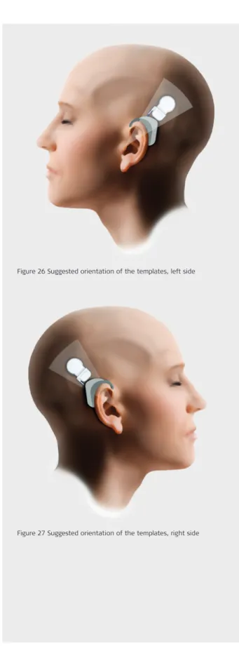
Figure 26 Suggested orientation of the templates, left side
Place the Processor Template behind the ear and position the Mi1210 Implant Template. The section of the Processor Template closest to the pinna (auricle) depicts the outline of MED‑EL’s BTE processors. The section furthest from the pinna represents the safety distance between pinna and stimula‑ tor of the implant. There are various orientation options. A suggested orientation for each ear is shown in Figure 26 and Figure 27, but the orientation depends on various factors, like e.g. the curvature of the skull.
Position the implant template in such a way that the SYNCHRONY ST Cochlear Implant will be in the hair bearing area. The lower part of the stimulator should be under or close to the temporal line, with an angle between 30° and 60°. The electrode exits on the lateral side of the implant. Therefore the electrode lead comes out superiorly for the left ear and inferiorly for the right ear.
Particular attention should be paid to the placement of the electrode lead on the skull. The position of the reinforced part of the electrode lead should be selected to facilitate the placement of the entire length of the electrode in a recessed channel. This ensures that the reinforced part of the electrode lead does not protrude into the mastoidectomy.
Once the implant template is in place, surgical ink may be used to mark its position on the surface of the skin. Surgeons may choose to transpose the position of the implant template onto the surface of the bone by using a hypodermic needle inserted perpendicularly to the skin at points along the side of the implant template.
When implanting a patient bilaterally, care should be taken with the placement of the implants. In particular the second side should be placed specifically to match the location of the first to give a symmetric appearance of the external part. The skull curvature and pinna position need to be taken into consideration when placing the second implant similar to the contralateral side.
Figure 27 Suggested orientation of the templates, right side
Choose the line of incision so that a well vascularised skin flap results. Make the incision 1–2 cm from the implant to ensure that the scar will not lie directly over the body of the implant. Incise the tissue with a scalpel and use bipolar electrocoagula‑ tion for haemostasis.
An example of a commonly used postaural incision is shown in Figure 28 and Figure 29. Postaural incisions start in the sulcus behind the pinna and extend posteriorly.
For greater mastoid bone exposure, each of these incisions
can be extended posteriorly in the shape of an arc. Figure 28 Minimal incision (left picture) and lazy “S” incision (right picture) – right ear
Figure 29 Minimal incision (left picture) and lazy “S” incision (right picture) – right ear – close up
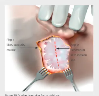
Flap 2: Periosteum with incision line Flap 1:
Skin, subcutis, muscle
Figure 30 Double layer skin flap – right ear
The incision is made and the wound is held open by retractors. At all times care should be taken to ensure that the flap is kept moist with damp surgical gauze.
Either a single layer skin flap – all four layers, skin, subcutis, muscle and periosteum are incised in a single cut, or a double layer skin flap can be performed.
A double layer skin flap may:
• reduce the chance of infection because the incisions are at different locations and layers, and
• allow better healing so it is often used for re‑implanta‑ tions and when encountering postauricular scar formation. Double layer skin flap (see Figure 30)
The four different tissue layers skin, subcutis, muscle, and periosteum are incised with two different incisions. First, the skin, subcutis and muscle are raised and retracted. Second, the periosteum is incised, the periosteum is freed from the surface of the bone and then retracted in another location. Various methods may be used when incising the periosteum. Care should be taken to avoid incision over the implant later on.
STEP 4‑A: Open Skin Flap
In order to achieve good magnetic hold and optimal signal transmission, the skin flap or the muscle may need to be thinned out so it does not exceed 6 mm.
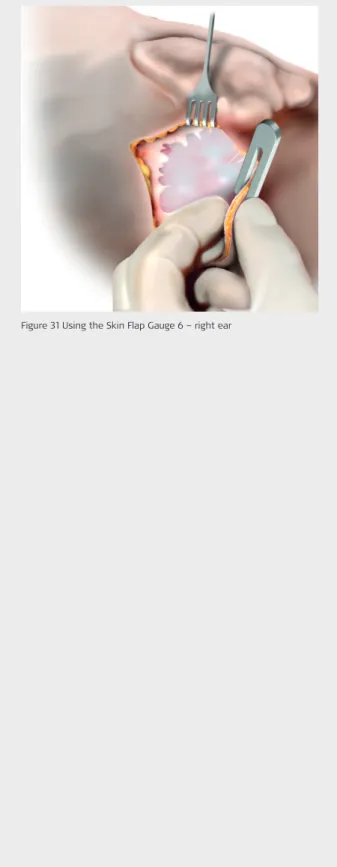
Evaluate the portion of the flap over the magnet and receiving coil with the Skin Flap Gauge 6, as shown in Figure 31. If the flap does not fit in the gauge loosely, carefully thin the flap until it does. It is important to avoid over‑thinning of the flap, which may result in wound complications. Care must be taken to avoid exposing hair follicles.
Figure 31 Using the Skin Flap Gauge 6 – right ear
CAUTION
Retractors may distort the actual position of the implant in relation to the pinna as the ear is retracted.
The Mi1210 Implant Template should be placed on the skull in order to visually check its proper position. The bony ear canal should be identified and re‑marking on the skull should be done if necessary (see Figure 32).
Figure 32 Marking the implant position with the Implant Template – right ear
CAUTION
Clear identification of the anatomical landmarks is required. When drilling, care should be taken to avoid exposing the dura inadvertently. If the dura is exposed as a landmark, exposure shall be kept to an absolute minimum. Inadequate large exposure or injury to the dura may reduce the barrier to future infection and may increase the potential risk for future meningitis. For example, neuro‑radiological follow‑up in cases of fractures of the anterior skull base have shown that foudroyantly progressing meningitis may occur, even years later. Similar mechanisms may also exist in respect of ear and mastoid surgery.
Facial nerve monitoring is recommended; when carried out, neuromuscular blockade should be avoided.
A standard cortical mastoidectomy is performed with a cutting burr, while ensuring good irrigation. A cortical overhang should be left, both superiorly and posteriorly; it can later serve as a natural support for the electrode lead as it is looped in the mastoid cavity.
The fossa incudis should be located, and the tip of the short process of the incus is identified to ensure the proper orienta‑ tion of the posterior tympanotomy. This important part of the operation should be practiced many times on human cadaver temporal bones before live surgery is performed. A triangular opening is made between the mastoid and the facial nerve, which is referred to as the facial recess. The posterior limit is the vertical portion of the facial nerve, the anterior limits are the annulus and chorda tympani, and the upper aspect is a posterior buttress at the level of the fossa incudis. Start drilling immediately below the fossa incudis, using a 3 mm dia‑ mond burr centred on the tip of the short process. Use high magnification and copious irrigation. Extreme care should be taken in drilling the posterior tympanotomy and the surgeon should be aware of any possible anatomical variants of the facial nerve.
Figure 33 Posterior epitympanotomy and posterior tympanotomy – right ear
POSTERIOR
INFERIOR
ANTERIOR
SUPERIOR
STEP 6: Drill Mastoidectomy and Posterior
Tympanotomy
The following should be visible after the posterior tympanot‑ omy: the long process of the incus, the incudostapedial joint, the stapes pyramid and stapedius tendon, the promontory and the round window niche (see Figure 33 and Figure 34). When the Fixation Clip will be used to stabilise the electrode lead inside the middle ear cavity care should be taken that the posterior buttress (see Figure 35) is created accordingly to the dimensions of the Fixation Clip. The recommended size of the posterior buttress is 2 mm.
Long process of the incus
Short process of the incus
Chorda tympani
RW niche Posterior buttress
Stapedius tendon
Figure 34 Posterior tympanotomy microscopic view – right ear
Figure 35 Posterior bridge prepared for the Fixation Clip – right ear
POSTERIOR
INFERIOR
ANTERIOR
SUPERIOR
EAS
• It is recommended to create a larger posterior tympanotomy (as compared to that of a stand-ard cochlear implantation) beside the posterior epitympanotomy in order to provide a better view as well as more space to manoeuvre the electrode array.
• Elevate a mucosal flap to avoid mucosal bleeding when opening the cochlea.
CAUTION
• The implant must be immobilised in a flat stimulator bed drilled in the temporal bone. The electrode lead should be placed in a ramp‑like bony channel without sharp edges to protect it against postoperative movement and excessive mechanical impact.
• The anterior stimulator edge should not be recessed to a depth more than 2 mm.
• All sharp edges of bone must be removed in order to avoid possible damage to the electrode lead. Drilling should be completed before the cochlea is opened to prevent any bone dust from entering.
• Protect the middle ear cavity from bone dust contamina‑ tion by closing it with medical gauze.
The implant must be immobilised in a flat stimulator bed drilled in the temporal bone. In adults, it may not be necessary to expose the dura, but in small children with a thin skull, drilling to the dura may sometimes be required in order to ensure that the stimulator is well recessed in its bed. If drilling down to the dura is necessary a bony island should remain. Ideally, the stimulator is recessed approximately 2 mm.
Once again the Mi1210 Implant Template can be used to mark the flatness on the skull and the correct position for the im‑ plant bed (see Figure 36).
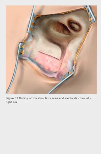
For protection and placement of the electrode lead, a smooth channel has to be drilled in the bone leading to the mastoid. Make sure that the channel is deep and wide enough to com‑ fortably accommodate the electrode lead.
If, for example, the implant is fixed with sutures, a diamond burr should be used to drill the holes so that the implant can be immobilised later. The suture holes should be drilled such that the sutures do not cross the electrode, but rather only cross the silicone over‑mold (see Figure 37.
Figure 36 Marking the implant position with the Implant Template – right ear
Figure 37 Drilling of the stimulator area and electrode channel – right ear
CAUTION
• Always use a slow turning diamond drill to avoid acoustic trauma when drilling the round window (RW) niche (ap‑ prox. 1000rpm).
• Try to keep the RW membrane intact until the insertion of the electrode.
A clear view of the RW membrane is fundamental for the suc‑ cessful performance of a round window opening. Therefore, the drilled area of the posterior tympanotomy is usually slightly larger than that of a standard posterior tympanotomy to get a clear view of the RW niche.
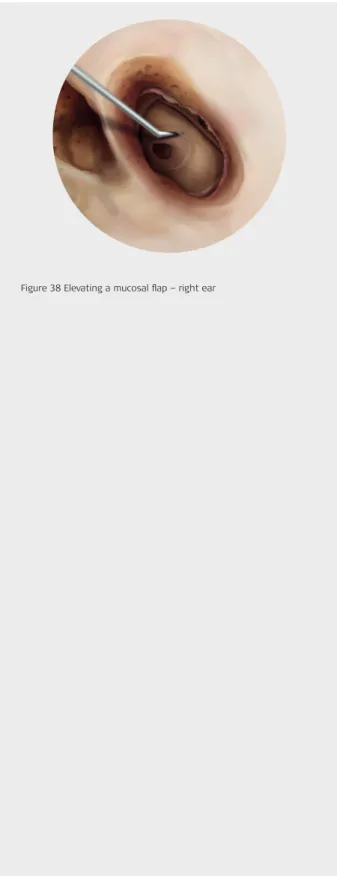
Before starting the preparation of the RW niche, a mucosal fold should be removed from the promontory. This prevents mucosal bleeding and provides better feedback from the tip of the drill (see Figure 38).
To facilitate the electrode insertion a portion of the anterior‑ inferior bony RW margin as well as the superior overhang of the RW niche needs to be drilled away. This increases the accessibility of the RW and prevents the electrode from being directed towards the modiolus. One potential risk associated with drilling the RW margin relates to its close proximity to the opening of the cochlear aqueduct. Care should be taken to avoid this inner ear structure.
Advantages of a RW opening:
• The amount of drilling is significantly reduced compared to a cochleostomy and no endosteal preparations in the direct vicinity of the basilar membrane are needed. • The round window always leads into the correct scala for
an electrode insertion – the scala tympani.
Figure 38 Elevating a mucosal flap – right ear
STEP 8 – VARIANT 1: Preparation for a
Round Window opening
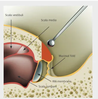
To enter the middle portion of the scala tympani and to get visualisation of the RW membrane, the posterior‑superior lip of the round window niche and the inferior margin of the round window should be drilled away. By doing this, the round window will be exposed for best insertion of the electrode array (see Figure 39).
The RW niche is drilled and exposure should be extensive enough to comfortably fit the electrode. An appropriate RW opening in relation to size, is dependent upon the type of electrode array chosen. Please refer to STEP 9, “Select Appro‑ priate Electrode Variant”.
Figure 39 RW niche anatomy
Scala media
Scala tympani Scala vestibuli
RW membrane Mucosal fold
EAS
• Begin drilling near the cochlea use a slow turning diamond drill to avoid acoustic trauma.
• To enter the middle portion of the scala tympani and to get visualisation of the round window membrane, the posterior-superior lip of the round window niche and the inferior margin of the round window should be drilled away to expose the round window membrane at least 0.8 mm. • Fill the electrode insertion site with corticosteroid. • Protect the middle ear cavity from bone dust
CAUTION
• For drilling the cochleostomy, always use a slowly turning diamond drill to avoid acoustic trauma (approx. 1000rpm). • Try to keep the endosteum intact until the insertion of the
electrode.
Before preparing to drill the cochleostomy, the mucosal fold should be removed over the promontory. This prevents mu‑ cosal bleeding and provides better feedback from the tip of the drill (see Figure 40).
The round window niche is identified and the cochleostomy is made inferior and slightly anterior to it. Many surgeons have a preferred technique to locate the best promontory point to begin drilling the cochleostomy. One recommendation is to use the width of the stapes as a measuring tool. The cochle‑ ostomy is made inferior to the stapedial tendon at a distance twice the width of the stapes and inferior and slightly anterior to the round window.
Figure 41 Drilling the cochleostomy inferior and slightly anterior to the round window – right ear
Figure 40 Removal of a mucosal fold & marking of cochleostomy – right ear
The cochleostomy is drilled and the exposure of the endos‑ teum should be big enough to comfortably fit the electrode. An appropriate cochleostomy size is dependent upon the type of electrode array chosen. Please refer to STEP 9, “Select Ap‑ propriate Electrode Variant”.
The bony lip of the cochleostomy is slightly smoothed with a small diamond drill bit.
Figure 42 Drilling the cochleostomy and leaving the endosteum intact when drilling (upper picture), smoothing the edges of the cochleostomy (lower picture)
EAS
• Begin drilling near the cochlea use a slowly turn-ing diamond drill to avoid acoustic trauma. • The cochleostomy should be drilled inferior and
slightly anterior to the round window annulus to achieve a scala tympani insertion and to avoid damage to the osseous spiral lamina. The endos-teum should be exposed to approximately 0.8 mm. • Fill the electrode insertion site with corticosteroid. • Protect the middle ear cavity from bone dust
Complete Cochlear Coverage (CCC) means stimulating the cochlea from the base to the apical region in order to stimu‑ late a maximum number of nerve fibres. Stimulation of the entire frequency range with a deeply inserted, long array provides the implant user with the best possible outcomes in speech performance measures and in sound quality.
MED‑EL Cochlear Implants are available with several different electrode options. For hearing preservation with especially atraumatic electrode arrays, or for even the most difficult cases of cochlear ossification, obstructions or malformations (see Figure 43).
Reduced Cochlear Duct Length or
Malformations
Depending on the cochlear duct length or the malformation of the cochlea, a FORM24, FORM19, FLEX24, FLEX20, MEDIUM or COMPRESSED electrode array may be appropriate for optimal cochlear coverage and stimulation.
Cochlear Ossification
The surgeon must be prepared for unexpected findings during surgery. Depending on the degree of ossification, different surgical approaches and electrode arrays can be used.
Partial Ossification
If only the inferior section of the basal coil is ossified, drilling along the basal turn can often reveal an open lumen in the further course of the scala tympani. In such cases, a FLEXSOFT, FLEX28 or STANDARD electrode array can be inserted. If the ossification is also in the ascending section of the basal turn, and a drill‑through cannot be achieved, there are various options:
• The cochleostomy can be widened in a superior direc‑ tion to reach the scala vestibuli. If this scala is patent, a FLEXSOFT, FLEX28 or STANDARD electrode array can be inserted.
• The COMPRESSED electrode array can be inserted into the tunnel which has been drilled into the lower basal coil.
Insertion Test Tools
Evaluation of possible electrode insertion length for the individual patient should be done prior to the surgery. This can be performed by a standard X‑ray or a CT scan. Furthermore, OTOPLAN can support healthcare professionals in preopera‑ tive planning and postoperative quality checks of otological procedures *.
With the help of the Insertion Test Tool, the Insertion Electrode (IE), the surgeon can establish whether the cochlear lumen is obstructed or if it is freely accessible up to different inser‑ tion depths depending upon the considered electrode variant planned for the implantation.
The Insertion Electrode variants shall not be used in patients where residual hearing shall be preserved.
*
STEP 9: Select Appropriate Electrode Variant
FLEXSOFT
A 31.5 mm electrode array featuring FLEX tip technology for increased me‑ chanical flexibility and enabling CCC.
Order number: 33336
1 19 platinum electrode contacts
Optimal spacing over a 26.4 mm stimulation range
2 Diameter at basal end: 1.3 m
3 FLEX‑Tip for minimal insertion trauma Dimensions at apical end: 0.5 × 0.4 mm
FLEX28
A 28 mm electrode array suitable for 96 % of all normal cochlear duct lengths featuring FLEX tip technology. Optimised for insertion into the apical region (CCC).
Order number: 33338
1 19 platinum electrode contacts
Optimal spacing over a 23.1 mm stimulation range
2 Diameter at basal end: 0.8 mm
3 FLEX‑Tip for minimal insertion trauma Dimensions at apical end: 0.5 × 0.4 mm
FLEX24
A 24 mm electrode array featuring FLEX tip technology and designed for combined Electric Acoustic Stimulation (EAS) with insertion less than 1.5 turns.
Order number: 33337
1 19 platinum electrode contacts
Optimal spacing over a 20.9 mm stimulation range
2 Diameter at basal end: 0.8 mm
3 FLEX‑Tip for minimal insertion trauma Dimensions at apical end: 0.5 × 0.3 mm
FORM 24™
A 24 mm electrode array featuring CSF SEAL designed for open (no obliteration or ossification) or malformed cochleae, especially Type II malformations. Also for cases where CSF leakage is expected.
Order number: 33340
1 24 platinum electrode contacts
Optimal spacing over a 18.7 mm stimulation range
2 Diameter at basal end: 0.8 mm
3 SEAL
4 Diameter at apical end: 0.5 mm
FORM 19™
A 19 mm electrode array featuring CSF SEAL designed to be used in cochleae with malformation, especially Type I and Type III, obliteration, or ossification. Also for cases where CSF leakage is expected.
Order number: 33339
1 24 platinum electrode contacts
Optimal spacing over a 14.3 mm stimulation range
2 Diameter at basal end: 0.8 mm
3 SEAL
4 Diameter at apical end: 0.5 mm
STANDARD
A 31.5 mm electrode array designed for long cochlear duct lengths.
Order number: 33333
1 24 platinum electrode contacts
Optimal spacing over a 26.4 mm stimulation range
2 Diameter at basal end: 1.3 mm
3 Diameter at apical end: 0.5 mm
MEDIUM
A 24 mm electrode array designed for cases where deep insertion is not de‑ sired or is not possible due to anatomic restrictions.
Order number: 33334
1 24 platinum electrode contacts
Optimal spacing over a 20.9 mm stimulation range
2 Diameter at basal end: 0.8 mm
3 Diameter at apical end: 0.5 mm
COMPRESSED
A 15 mm electrode array designed for partial ossification or malformation of the cochlea.
Order number: 33335
1 24 platinum electrode contacts
Optimal spacing over a 12.1 mm stimulation range
2 Diameter at basal end: 0.7 mm
3 Diameter at apical end: 0.5 mm
FLEX 20
A 20 mm electrode array featuring FLEX‑ Tip technology and designed to be used in cases of partial deafness or for other specific needs or surgical preferences.
Order number: 33341
1 19 platinum electrode contacts
Optimal spacing over a 15.4 mm stimulation range
2 Diameter at basal end: 0.8 mm
3 FLEX‑Tip for minimal insaertion trauma Dimensions at apical end: 0.5 × 0.3 mm
1 19 platinum electrode contacts
Optimal spacing over a 20.9 mm stimulation range
2 Diameter at basal end: 0.8 mm
3 FLEX‑Tip for minimal insertion trauma Dimensions at apical end: 0.5 × 0.3 mm
FLEX26
A 26 mm electrode array featuring FLEX tip technology and designed to increased mechanical flexibility for reduced insertion force.
Order number: 36631
FLEX‑Tip FLEX‑Tip FLEX‑Tip FLEX‑Tip FLEX‑Tip SEAL SEAL
CAUTION
• Monopolar electrosurgical instruments must not be used in the head and neck region. If bipolar electrosurgical instruments are used, the tips of the cautery must be kept at least 5 mm away from the reference electrodes on the stimulator housing and any contacts of the electrode array.
• Additional immobilisation of the implant needs to be performed.
• If sutures are chosen for immobilisation of the implant do not place the sutures directly over the electrode lead.
Additional immobilisation of the implant needs to be per‑ formed (e.g. with sutures). It should be conducted in such a way that there will be no postoperative movement. Continu‑ ous movement may result in mechanical fatigue and subse‑ quent premature failure of electrical connections.
When the implant is immobilised with sutures, the holes drilled in STEP 7 should be used to secure the implant in its bed and the electrode should be placed into the drilled channel leading into the mastoid. Make sure the electrode channel is deep enough to prevent the tie‑down from exerting pressure and damaging the electrode. MED‑EL recommends the use of the following technique (details in Figure 44).
Good physical and thus stable electrical contact between stimulation reference electrode and surrounding tissue is es‑ sential for electrical stimulation. Therefore do not place any fixation sutures directly over the reference electrode and do not recess the stimulator too deeply to avoid any air gap over the reference electrode.
In the event that the placement of the implant led to the protrusion of the reinforced part of the electrode into the mastoidectomy the following measures should be undertaken: • Gently pre‑shape the reinforced part of the electrode
lead; without surgical instruments, using your hands only. • Try to coil the rest of the electrode lead into the mas‑
toidectomy, in such a way that additional pressure is not placed on the outer ear canal or the periosteum closing the mastoid cavity.
Figure 44 Implant immobilised with double stitches – right ear
Before inserting the electrode array into the cochlea, either the RW membrane for a RW insertion or the endosteum for a cochleostomy insertion, needs to be incised.
Either a micro‑lancette or a micro‑hook can be used to open the cochlea (see Figure 45, Figure 46 and Figure 47).
Figure 47 Endosteum incision with a micro‑lancette Figure 46 Endosteum incision with a 45° micro‑hook Figure 45 RW membrane incision with a 45° micro‑hook
EAS
• Prior to opening the cochlea, clean the surgical field, change gloves, remove the gauze used to keep bone dust out of the middle ear cavity and administer a single dose of intravenous corticos-teroids to protect the inner ear.
• Place a drop of corticosteroid on the round win-dow membrane or endosteum to reduce fibrotic reaction and cover it with a drop of hyaluronic acid. This will keep the corticosteroid in place and protect it from bone dust.
• Using a micro-lancette or micro-hook, carefully incise the round window membrane in its inferi-or-anterior quadrant to approximately 0.8 mm. • Using a micro-lancette or micro-hook, carefully
incise the endosteum to approximately 0.8 mm. • Avoid suctioning in the open region of the cochlea.
CAUTION
• Only surgical tools approved by MED‑EL should be used to insert the electrode array into the cochlea.
• Under no circumstances should any force be used during electrode insertion.
• Insertion of an electrode array into the cochlea may result in the loss of residual hearing which was present in that ear prior to surgery.
Begin to insert the active array in a way that the electrode lead is not coiled up or in the line of sight before finishing the insertion.
Perform the excess lead management after completing elec‑ trode insertion.
It is important for the electrode array to approach the anterior portion of the basal turn at an angle so that it slides along the lateral wall of the scala tympani. Therefore, the recommended direction for insertion of the electrode array is coming from the posterior buttress at the incus and progressing towards the round window opening. This procedure, known as tangen‑ tial insertion, facilitates deep electrode insertion (see Figure 48).
The individual insertion direction for each case should be con‑ sidered in order to reach a tangential electrode insertion (see Figure 49). Non‑tangential insertion should be avoided. Surgical tools approved by MED‑EL should be used to insert the electrode array into the cochlea (please see Chapter 4 Surgical Tools). Use of lubrication or anti‑inflammatory com‑ pounds during electrode insertion is up to the surgeon.
Figure 48 Direction of electrode insertion – right ear
Figure 49 Insertion vector to reach a tangential electrode insertion
The electrode lead is held very carefully at the proximal thicker part, just above the marker ring. The tip of the electrode array is guided toward the cochlea opening. After the tip is gently manoeuvred further into the cochlea, the electrode array can be gripped between the contacts (see Figure 50). During insertion it is essential that the electrode contacts are not mechanically damaged and that no excessive force is used. Please be aware that sealing of the cochlear opening with the marker ring should not be achieved with the MEDIUM and COMPRESSED Electrode Arrays.
Figure 50 Detail of electrode insertion – manoeuvre the electrode array between the contacts & after the marker ring
EAS
• Since EAS candidates show good residual hear-ing in the low frequencies, a tangential insertion -i.e. ideal electrode insertion direction to reach the lateral wall of the cochlear at the beginning of the basal turn in the hook region- is strongly recommended for straight electrode designs. This ensures that our highly flexible electrodes glide along the lateral wall when inserted further into the cochlear, minimising possible damage to the delicate structures and at the same time allow a “deep insertion” (as desired by the surgeon).
If resistance is encountered before reaching the marker ring, the electrode array may buckle. In such cases, electrode inser‑ tion should be stopped. Excessive force should not be used, as it may result in intra‑cochlear damage.
The following measures may be helpful in such situations: • Carefully rotate the electrode
Due to the unique oval design of the electrode array, the electrode can be slightly rotated to allow it to slide deeper into the cochlea.
• Small movements close to the insertion site
Hold the electrode no more than 2 mm from the cochle‑ ostomy or round window opening. Gently insert the electrode with one stroke, release it and grasp it again 2 mm from the insertion side. Repeat this procedure until complete insertion is achieved.
• Slow the rate of insertion
Slow the speed that the electrode is introduced into the opening. Frequent pauses during insertion can allow the electrode to gently slide along the cochlear duct. • Use of lubricant
As known from soft surgical techniques, the use of a lubri‑ cant can help smoothing the electrode insertion.
Figure 51 Full insertion of the electrode array – forceps positioned behind the marker ring – right ear
EAS
• Immediately start the electrode insertion through the drop of corticosteroid and hyalu-ronic acid.
• The recommended direction for insertion of the electrode array is coming from the posterior buttress at the incus and progressing towards the round window opening.
CAUTION
• To minimise the risk of postoperative infection additional sealing of the cochlear opening should be done for all MED‑EL electrode arrays.
• Once the electrode array has been inserted into the cochlea, the electrode lead should be fixed so that no postoperative movement will occur.
• Please be aware that sealing of the cochlear opening with the marker ring should not be achieved with the MEDIUM and COMPRESSED Electrode Arrays.
When the electrode array is fully inserted, the marker ring will aid sealing the cochlear opening during surgery and provide an additional point of fixation (see Figure 52). This sealing will only take place with the FORM24, FORM19, FLEXSOFT, FLEX28, FLEX26, FLEX24, FLEX20 and STANDARD Electrode Array fully inserted.
Please be aware that sealing of the cochlear opening with the marker ring should not be achieved with the Medium and Compressed Electrode Arrays since their intended insertion depths are 24 mm and 15 mm, respectively, and the marker ring is located at a distance of 31.5 mm from the tip of the electrode array.
For all MED‑EL Electrode Arrays, use a small fascial graft around the electrode array at the entrance to the cochlea to secure the electrode array and to seal the opening. Before ap‑ plication, rinse the small pieces with saline solution to prevent contamination of the electrode and to increase flexibility.
Figure 52 The marker ring of the STANDARD Electrode Array can seal the cochlear opening, aiding in its fixation – right ear
Figure 53 The electrode lead should be loosely placed below the cortical overhang of the mastoidectomy – right ear
EAS
• To seal the cochlea, use a small fascial graft. To prevent contamination of the electrode and to increase flexibility, rinse the fascial graft with saline solution.
If you choose to secure the electrode lead in the posterior tympanotomy, fibrin glue or bone paté can be used. MED‑EL offers a Fixation Clip to secure the electrode lead to the pos‑ terior buttress (incus bridge).
Securing the electrode lead with the
Fixation Clip*
Order number: 09917
CAUTION
• The Fixation Clip shall not be used in the case that the pos‑ terior buttress is not suitable for placing the Fixation Clip. • The recommended diameter of the posterior buttress is
2 mm.
• Accidental bending of the Fixation Clip during removal from its packaging must be avoided in order to prevent functional damage.
• Care should be taken that during the fixation of the bone fixation clip the Incudostapedial joint and the posterior incudal ligament are not harmed and the movements of the ossicles are not inhibited.
• Care should be taken not to squeeze or damage the electrode.
The Fixation Clip shall be used exclusively with MED‑EL elec‑ trodes that have a diameter of 1.3 mm at the distal part of the electrode lead (see Figure 55).
The openings are not of the same size. The larger opening of the Fixation Clip is the bone fixation clip and the smaller opening of the Fixation Clip is the electrode fixation clip (see Figure 56).
Figure 54 Fixation Clip Ms010103
Figure 55 Distal part of the electrode lead Electrode array
Distal part of the electrode lead
Figure 56 Dimensions of the Fixation Clip
1.4
mm
1.15
mm 2 mm
1 mm
5.9 mm
2.9
mm
Electrode fixation clip Bone fixation clip
First the larger clip (bone fixation clip) shall be placed on the posterior buttress (see Figure 57).
Next, the bone fixation clip shall be properly crimped to the posterior buttress (see Figure 58). For crimping the Fixation Clip a micro forceps should be used (e.g. Hartmann Alligator Forceps, 8 mm).
After fixing the bone fixation clip, the electrode fixation clip shall be closed over the electrode lead so that both ends of the electrode fixation clip come together and the clip is com‑ pletely closed (see Figure 59).
The electrode lead is longer than required in order to ac‑ commodate anatomical variants and to compensate for skull growth in children.
The electrode lead is looped in the mastoid cavity well below the surface of the bone, using the cortical overhang to hold it in place to avoid postoperative movements due to contrac‑ tions of the temporalis muscle (see Figure 60).
Additional immobilisation of the electrode lead inside the electrode channel could be done, e.g. with bone paté or bone wax.
Figure 60 The electrode lead should be loosely placed under the cortical overhang – right ear
Figure 57 Placement of the Fixation Clip on the posterior buttress
Figure 58 Bone fixation clip crimped on the posterior buttress
Figure 59 Electrode fixation clip closed over the elec‑ trode
At this stage intra‑operative recordings like Impedance Field Telemetry (IFT), Electrically Evoked Stapedius Reflex Threshold (ESRT), Electrically Evoked Brainstem Response (EABR) or Audi‑ tory Nerve Response Telemetry (ART) can be performed. Intra‑operative measurements are performed with the appro‑ priate MED‑EL application software and the MED‑EL hardware interface system. For details please refer to the applicable Software user manual. It is not possible to sterilise any com‑ ponent of the MED‑EL hardware interface system. When used in a sterile environment, the coil and cable should be covered with sterile material (i.e. “sterile sleeve”). The appropriate coil should be used during intra‑operative recordings.
Since the coil should not be placed directly on the implant, either sterile gauze drenched in saline solution or the skin flap should be placed between the coil and the implant. Moistening the underside of the skin flap with sterile saline or pooling sa‑ line over the ground electrode of the implant prior to perform‑ ing intra‑operative recordings may improve readings.
IFT (Impedance Field Telemetry)
After the implant is in place, a telemetry check allows: • individual electrode impedance measurements • verification of the absence of short and open circuitsbetween electrodes
• determination of intra‑cochlear voltage distribution As with any telemetry system, intra‑operative impedance testing may not provide an accurate representation of later electrode function. “High” values observed intra‑operatively may be caused by air bubbles on the electrode contact surface. These generally dissipate within a few hours or days after surgery.
ESRT (Electrical Stapedius Reflex Threshold)
If ESRT thresholds are measured, care should be taken that no muscle relaxant is used during the last half hour before performing the measurements.Note that observation of the reflex is not possible in some implanted patients due to various physiological and anatomical reasons. In addition, observation of the reflex may not be pos‑ sible due to anaesthesia. Therefore, absence of a reflex should not be taken as an indication of implant malfunction or lack of auditory response without other more direct evidence. Intra‑operatively, the presence of the reflex can be monitored either by direct observation of the ipsilateral tendon, through the microscope, or by impedance probe measurements in the contralateral ear. Direct observation is employed in most cases, as this is normally straightforward and does not require additional equipment. Probe measurements are usually re‑ stricted to research studies.
EABR (Electrically Evoked Brainstem
Response)
With the addition of the EABR task, it is possible to measure and record the response of the entire auditory pathway to stimulation from the implant. EABR recordings can be used to determine the best placement of an Auditory Brainstem Implant during surgery, and they can also provide interesting information on the function of the whole auditory pathway. The MED‑EL application software EABR parameters can be adjusted to facilitate recording of early, middle and late electri‑ cal potentials. To obtain measurements with the EABR task, it is necessary to also use a separate neurodiagnostic computer with a trigger input, along with scalp recording electrodes.