The Synthesis and Optimization of Conjugated Polymers
for Photovoltaic Applications
Samuel Chesson Price
A dissertation submitted to the faculty of the University of North Carolina at Chapel Hill in
partial fulfillment of the requirements for the degree of Doctor of Philosophy in the
Department of Chemistry.
Chapel Hill
2011
© 2011
Samuel Chesson Price
Abstract
Samuel Chesson Price:
The Synthesis and Optimization of
Conjugated Polymers for Photovoltaic Applications
(Under the direction of Professor Wei You)
Conjugated polymer solar cells have the potential to be a cheap, light weight, robust
source of solar power and could contribute to solving the energy problems our future faces.
The primary limiting factor for commercialization of these devices is the power conversion
efficiency, which is governed by the conjugated polymer semiconductor in the active layer of
these devices. However, the current state of the art materials are not optimized, and progress
in the design of conjugated polymers must be made for these devices to be financially viable.
Synthetic modification of the polymer p-type semiconductor is necessary to fully understand
the structure-property relationships that govern the underlying principle performance criteria
of these polymer photovoltaic cells. By synthesizing new conjugated polymers with a variety
of chemical structures, more insight can be gained into the factors that govern the band gap,
oxidation and reduction potential, hole mobility, and phase separation behavior of the
Additionally, these polymers are able to form exceptionally thick films and still maintain
high efficiencies. The exceptional performance of these materials grants a unique insight that
Acknowledgements
First & foremost, I’d like to thank my advisor, Wei You. Wei is likely the most patient professor I’ve
ever encountered, and he gave me the space to develop intellectually on my own (aka, propose a ton of bad
ideas that ultimately fail). I can recall several days where Wei and I were extremely busy, and yet I still found
myself in Wei’s office for hours, discussing some interesting paper or result that just came in. If all the
supervisors I ever have are like Wei, I would be truly blessed.
Secondly, I want to thank David Vernon, my high school chemistry teacher. Vernon set this whole
ridiculous chemistry trip in motion. He changed my attitude towards school by introducing me to a subject that
was analytical, yet far more practical than any of the other math or science classes I had before. Vernon is still
the best chemistry educator I’ve ever experienced, and I attribute part of my current success to the knowledge
foundation I gained in his class.
I also want to thank Jeremy Niskala, who accompanied me as Wei’s first class of graduate students.
Jeremy is an excellent friend and researcher, and being around his incredible work ethic was inspiring.
I want to thank Huaxing Zhou, Liqiang Yang, Andrew Stuart, Rycel Uy, Phil Hamilton, Jason Dyke,
Nabil Kleinhenz, Paul Hoertz, and Shengqiang Xiao. I’ve thoroughly enjoyed working with all of you, and each
of you have contributed to this thesis.
Finally, I want to thank my family and Olivia. Without Olivia’s support through all the frustrating
Table of Contents
Chapter 1: Introduction...2
Preliminary Organic Photovoltaics...3
Device Mechanisms and Performance in Polymer Solar Cells ...5
Polymer Design Strategy...10
Chapter 2: Polycyclic Aromatics with Flanking Thiophenes: Tuning Energy Level and Band Gap of Conjugated Polymers for Bulk Heterojunction Photovoltaics ...17
Monomer and Polymer Synthesis...19
Optical and Electrochemical Properties ...23
Photovoltaic Properties...25
Experimental Section ...30
Chapter 3: Low band gap polymers based on benzo[1,2-b:4,5-b′]dithiophene: rational design of polymers leads to high photovoltaic performance...36
Monomer and Polymer Synthesis...37
Optical and Electrochemical Properties ...38
Photovoltaic Properties...39
Experimental Section ...41
Chapter 4: Fluorine Substituted Conjugated Polymer of Medium Band Gap Yields 7% Efficiency in Polymer−Fullerene Solar Cells...45
Synthesis of Monomers and Polymers ...47
Optical and Electrochemical Properties ...49
Photovoltaic Properties...51
Experimental Section ...55
Chapter 6: Future Research Directions...65
Appendix 1: Benzodithiophene Synthesis ...68
Appendix 2: Supporting Information for Chapter 2 ...75
Appendix 3: Supporting Information for Chapter 3 ...88
Appendix 4: Supporting Information for Chapter 4 ...94
Appendix 5: Supporting Information for Chapter 5 ...109
Chapter 1: Introduction
The rising cost of traditional, non-renewable energy sources have placed increased public attention
on the development of renewable, cheap energy sources for economic and national security reasons.
Photovoltaic cells based upon polymer semiconductors are expected to be part of the solution to alternative
energy needs for the future, and power conversion efficiencies of such devices are currently nearing the
range for commercial application.
Polymer solar cells will provide two distinct potential advantages over current silicon based
technology. First, polymer photovoltaics are expected to be lightweight, flexible, and mechanically robust
when compared to polycrystalline silicon cells. Secondly, polymer photovoltaics may be manufactured
using rapid roll-to-roll, solution printing techniques, rather than the slow, low yielding, thermally
inefficient processes which characterize current solar cell manufacturing. Therefore despite modest power
conversion efficiencies when compared to inorganic semiconductor solar cells, drastic cost reductions and
more potential applications drives the current research interest in polymer solar cells.
Additionally, polymer photovoltaic cells offer the opportunity for extensive modification through
chemical synthesis. The typical film thickness for a polymer photovoltaic cell is less than one micro, which
would require less than one gram of polymer semiconductor to make a solar cell of one square meter.
Significant synthetic modification of the polymer material is not expected to significantly drive up the cost
of the final device, given the small amount of material required. Therefore, the chemical synthesis and
optimization of conjugated polymers for use in these photovoltaic applications has the potential to
Preliminary Organic Photovoltaics
The first organic photovoltaic cell was developed in 1985 by C. W. Tang at the Eastman Kodak
Corporation using copper phthalocyanine (CuPc) dye as the p-type, electron donating semiconductor, and a
perylene derivative (1) as the n-type semiconductor.1 This bilayer device was roughly 1% efficient,
however it was manufactured using high vacuum evaporation methods to deposit the films used for the cell.
ITO Coated Glass
CuPc (30 nm)
perylene derivative (1) (50 nm)
silver
e
-h
+ITO Coated Glass
CuPc (30 nm)
perylene derivative (1) (50 nm)
silver
ITO Coated Glass
CuPc (30 nm)
perylene derivative (1) (50 nm)
silver
e
-h
+Figure 1.1. Materials used in the first organic photovoltaic cell. The perylene is the electron transporter,
and the phthalocyanine transports the holes to the ITO anode.
Small molecules such as CuPc are difficult to deposit using low temperature, rapid methods at
atmospheric pressure. However, soluble polymer materials readily form homogenous thin films using
printing and other low cost solution deposition techniques. Recognizing this potential of conjugated
polymers, the research partnership of Nobel laureate Alan Heeger & Fred Wudl began investigating
conjugated polymers for use in photovoltaics. First in 1992, they found that a conjugated polymer,
MEH-PPV, transferred an electron to the n-type semiconductor buckminsterfullerene when excited by light, much
in the same way as the CuPc-perylene tandem in Tang’s work.2 The buckminsterfullerene (C60) was poorly
soluble in most organic solvents, and thus in order to develop solution processable photovoltaic cells, Wudl
began investigating methods to increase the solubility of the fullerene derivative without altering its
electron accepting and electron transporting properties. In 1995, Wudl reports the synthesis of
disrupts the aggregation of the PC61BM in solution, increasing its solubility without drastically affecting the
electrochemical behavior.
Figure 1.2. The first organic semiconducting materials developed for use in polymer photovoltaic cells.
This discovery lead to the development of the first polymer photovoltaic cells using
MEH-PPV:PC61BM composites, which were fabricated by spin casting a blend of the two materials from
solution.4 This blend, coined a bulk-heterojunction, works especially well because the polymer and
fullerene demix and phase segregate, forming a bi-continuous interpenetrating network of p-type and
n-type materials. This allows for a larger interfacial area between the two semiconductors, increasing the
charge separation efficiency.
Anode Cathode
+
+
--Figure 1.3. A bulk heterojunction, where charges are split at the polymer:PC61BM interface, and travel
This work forms the primary basis for polymer solar cells. Advances have been accomplished,
especially identifying the governing fundamental principles which affect the performance of these devices.
However, the innovative idea of an organic solar cell which can be quickly and cheaply fabricated using
solution processing was first explored in these four reports.
Device Mechanisms and Performance in Polymer Solar Cells
The overall power conversion efficiency (η) of any photovoltaic cell is determined from the equation:
in oc sc
P
FF
V
J
=
η
where Jsc is the short circuit current density (mA/cm2), Voc is the open circuit voltage (V), FF is the fill
factor (%), and Pin is the irradiance (mW/cm2). The values of the three variables in the numerator are
determined from a current density vs. voltage plot obtained while irradiating the cell with light. The Jsc is a
measure of how many charges are extracted from the photovoltaic cell when no opposing voltage is
applied, and the Voc is a measure of the voltage which must be applied in order to prohibit all charges from
being extracted from the cell.
Jsc= 12.45 mA/cm2
Voc= 0.71 V
MPP
Figure 1.4. Typical current density vs. voltage plot for a conjugated polymer material, showing the Jsc, Voc,
The fill factor is given by the following equation: sc oc M M
J
V
J
V
FF
=
pp ppwhere the VMpp and JMpp are the current and voltage at the maximum power point on the current density vs.
voltage plot.
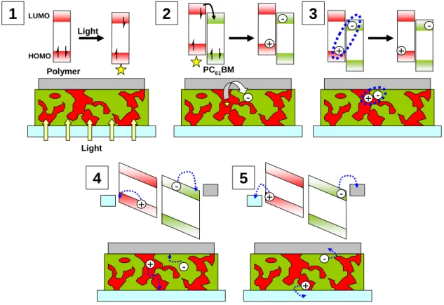
The device performance of polymer photovoltaic cells occurs in five different phases: 1) light
absorption; 2) exciton diffusion and charge separation; 3) charge transfer complex dissociation into free
charge carriers; 4) free charge transport through the matrix; 5) charge collection at the electrodes.
Light Polymer HOMO LUMO
1
Light2
--PC61BM3
+ + --+ + --+ + --+ +4
+ + --+ + --5
+ + --+ +--Figure 1.5. Summary of the five phases involved in power generation in polymer photovoltaic cells.
Light absorption by either the conjugated polymer or the fullerene is the first critical energy
harvesting phase in the photovoltaic process. First, light passes through a transparent anode, which is
typically a double layer of tin doped indium oxide (ITO) coated with poly(3,4-ethylenedioxythiophene)
doped with poly(styrenesulfonate) (PEDOT:PSS). Both layers are over 80% transmissive in the visible
transparent cathodes used for inverted devices have also been explored.5-7,8-10 However, for this particular
study and the vast majority of research on conjugated polymer solar cells, PEDOT:PSS coated ITO is the
transparent anode material employed.
The polymer material typically absorbs the majority of the light harvested by the polymer
photovoltaic cell. The energy of the light absorbed must be greater than the band gap (Eg) of the polymer,
or the energy difference between the HOMO and the LUMO of the polymer. Therefore, the smaller the
band gap of the polymer, the amount of light absorbed will increase and the Jsc will increase as well. Band
gaps for polymer photovoltaic materials typically range between 2.0-1.4 eV, which would allow for a
maximum of 18-47% of the incident photon flux from the sun to be absorbed.11 The amount of light
absorbed is also dependent on the film thickness, and the absorption coefficient of the polymer. Thicker
films will allow more photons to be absorbed, especially in regions of the absorption spectrum where the
polymer absorption coefficient is low. The PC61BM also absorbs a non-trivial amount of light, especially in
the region between 300-400 nm. Other fullerene derivatives such as [6,6]-phenyl C71 butyric acid methyl
esters (PC71BM) have been synthesized in order to increase the light absorption from the fullerene
component, however their effect on the photovoltaic performance is modest in most cases.12
Polymer HOMO LUMO
Polymer hν ≥Eg
E
gEg= 625 nm
Figure 1.6. Absorption of light greater than or equal to the band gap of the polymer creates a singlet
excited state. The band gap is determined from the absorption edge of the UV-Visible absorption spectrum.
In the polymer absorption spectrum shown, the band gap of each polymer is roughly 625 nm or 1.98 eV.
UV-Visible spectrum reprinted with permission from ref. 5.
After the light has been absorbed by the active layer, the semiconductor forms an excited state
states with finite lifetimes which require anywhere from 0.1 to 0.5 eV to dissociate the exciton into charges
on two separate molecules.14-16 Excitons are dissociated at the polymer:fullerene interface, and the required
distance of the exciton from the interface in order to dissociate is estimated anywhere between 5 nm for
PC61BM excitons, to values as large as 20 nm or even 80 nm in conjugated polymer excitons.17-19 If the
charges do not reach the polymer:fullerene interface, this reduces the Jsc. Clearly close proximity to the
polymer:fullerene interface is critical, and bulk heterojunctions currently provide the best method for
exciton dissociation since the domain sizes of the polymer and fullerene are usually small and in close
contact.
Exciton splitting is an exceptionally fast process once the exciton is close enough to the interface
to dissociate, faster than any other exciton decay mechanisms. Therefore exciton splitting is highly efficient
for materials with the required 0.1-0.4 eV LUMOpolymer-LUMOPCBM offset, with a yield close to unity.2 Any
energy difference greater than 0.4 eV is wasted, and therefore minimizing the LUMO-LUMO gap to the
minimal value is highly important for highly efficient polymer solar cells.
Polymer LUMO
PC61BM LUMO ∆E ≥0.1-0.4 eV
PC61BM Polymer
~60 ps
Figure 1.7. Exciton dissociation occurs if the energy offset between the LUMO of the two organic
semiconductors is greater than or equal to 0.1-0.4 eV. The process is rapid, and occurs in less than 60
picoseconds.
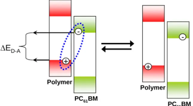
After exciton dissociation, the two separated charges on the polymer and fullerene create a
coulombically bound radical ion pair, which is called a charge transfer complex or charge transfer
exciton.20,21 These bound charge pairs at the polymer:fullerene interface determine the Voc of the polymer
photovoltaic cell, which is predominantly determined by the difference between the HOMO of the polymer
and the LUMO of the PC61BM (∆ED-A). 22
components, the nature of the polymer:fullerene interface, and the relative permittivity of the film also
affect the Voc of the photovoltaic cell. 22,23,24 The charge transfer complex may recombine to the ground
state if it is not dissociated into free charge carriers.
--+ +
∆ED-A
PC61BM Polymer
--+ +
PC61BM Polymer
Figure 1.8. Charge transfer complex must reversibly dissociate into free charge carriers to produce current.
Energy difference between the HOMO of the polymer and the LUMO of the fullerene (∆ED-A) is the
primary determining factor for the Voc.
Once the charge transfer complex has been dissociated into free charge carriers, the internal
electric field applied by the electrodes of the photovoltaic cell cause the charges to move towards their
corresponding electrodes. The rate at which these charges move for a given electric field is determined by
the charge carrier mobility (µ) which has units of velocity multiplied by the inverse of the electric field
(cm2 V-1 s-1). Fullerenes, being spherical, allow for π cloud overlap in any orientation relative to other
fullerenes. Therefore even in a disordered system such as a bulk heterojunction, the π-π distance between
fullerenes is minimal and the electron mobility is quite rapid. A balanced charge mobility between
electrons and holes and an optimal phase segregated morphology will prevent free charge carriers from
recombining.
Optimal Morphology Suboptimal Morphologies
Figure 1.9. The optimal morphology is a phase segregated network, where both networks are continuous
and the domain sizes are between 40-200 nm. A suboptimal morphology contains islands of material not
Lastly, charges must cross the interface between bulk active layer and the electrodes. The work
function of the electrodes must be lower (in absolute value) than the HOMO of the polymer and the LUMO
of the PCBM. Otherwise, injection barriers from non-ohmic contacts will result which limit the open circuit
voltage of the photovoltaic cell.25 Therefore low work function metals evaporated in high vacuum such as
aluminum and calcium are the predominant cathode materials used for photovoltaic cells at the research
scale. The PEDOT:PSS has a work function of roughly 5.0 eV, which is sufficient to inject holes into
polymers with HOMO energy levels as low as -5.8 eV.
Polymer Design Strategy
The conjugated polymer in bulk heterojunction photovoltaic cells is required to do essentially
three things; 1) Absorb light; 2) Split excitons efficiently with the minimum LUMO-LUMO offset
required; 3) Transport holes to the anode. All three of these criteria are affected by the polymer structure,
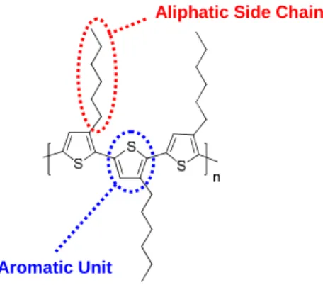
and even small changes in structure can create large effects on the properties of the material. There are two
main parts to each conjugated polymer structure, the aromatic units and the aliphatic side chains.
Aromatic Unit
Aliphatic Side Chain
Figure 1.10. The two main parts of the conjugated polymer, region-regular P3HT.
The aromatic units should be selected with planarity, a low LUMO, and non-intrusive positions to
attach the aliphatic chains as the key design parameters of the material. Control of the electronic energy
levels of the conjugated polymer semiconductor is the first and easiest design parameter to be considered.
The quinoidal stabilization approach lowers the band gap by stabilizing the quinoidal resonance
form of the conjugated polymer, typically by forming stabilizing aromatic systems when the polymer is in
the quinodal resonance form. This approach was pioneered by Fred Wudl in 1984 when he reported the
synthesis of poly(isothianapthalene), which exhibited a band gap of 1.0 eV.27 By stabilizing the quinodal
structure, there is more double bond character between the two aromatic monomer units. This leads to an
elevation of the energy level of the HOMO and a reduction of the LUMO, thus reducing the band gap. This
method allows for control of the band gap, and more importantly the LUMO of the polymer so that the
LUMOpolymer-LUMOPCBM offset may be minimized. In 2009, Luping Yu and coworkers developed a
polymer which employed this method for controlling the band gap, and photovoltaic cells using this
polymer obtained 6.8% efficiency.28
Aromaticity Stabilizes Quinoidal Structure, Lowers Eg
Eg = 1.7 eV
Eg = 1.0 eV
Figure 1.11. Quinoidal resonance structure is stabilized by the formation of a benzene ring in
poly(isothianapthalene). This raises the HOMO and lowers the LUMO, thus reducing the band gap by 0.7
eV over unsubstituted polythiophene.
The second method for controlling the electrochemical LUMO and the band gap is the ICT
approach (sometimes referred to as the Donor-Acceptor approach). Pioneered by Havinga & coworkers
working for the Phillips Corporation in 1992, this approach uses alternating electron rich and electron poor
heterocycles to control the HOMO and LUMO energy levels.29 This method also functions by stabilizing
the quinoidal resonance structure, except that the mechanism of the stabilization is different. The HOMO
adopted by the polymer is roughly the HOMO of the electron rich unit, and the electron poor unit primarily
dictates the position of the LUMO energy level. This is advantageous since the energy levels can be
In one particularly illustrative example, Tour & coworkers synthesized polythiophene with alternating
diamino and dinitro groups at the β-positions of the thiophenes, reducing the band gap by 0.7 eV over
unfucntionalized polythiophene.30
Eg = 1.0 eV
Figure 1.12. ICT approach. To affect only the LUMO, the electron rich unit can be omitted from the
polymer.
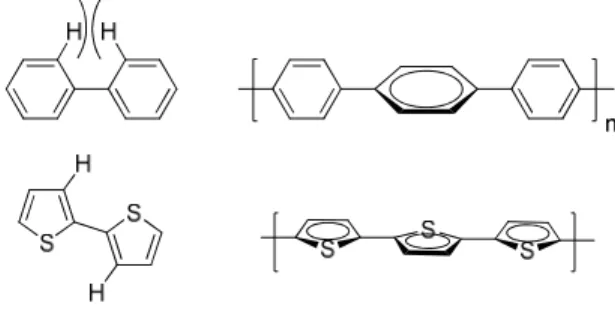
The aromatic units utilized on the polymer backbone should also be selected so that they minimize
any steric interactions that would cause the aromatic units to twist out of plane from one another. An
illustrative example of this is the difference between poly(p-phenylene) and polythiophene.
Poly(p-phenylene) has significant steric hindrance between the two hydrogens on adjacent phenyl rings. This
prevents the phenyl rings from being coplanar, and thus increases the band gap significantly. Polythiophene
on the other hand presents no such steric issues, and creates a coplanar polymer structure. Regio-regular
poly(3-hexylthiophene) (rr-P3HT) is possibly the most notable application of this principle.31,32 Head to
head couplings in regiorandom P3HT cause undesirable steric effects, which leads to backbone twisting
and red-shift in the λmax by roughly 25 nm.
Figure 1.13. Polythiophene adopts a coplanar structure, while steric factors prohibit this planarity in the
Figure 1.14. Head to head coupling in Regiorandom P3HT causes undesirable backbone twisting due to
steric effects. Reprinted with permission from ref. 34.
As illustrated in the P3HT example, the regiochemical placement of the side chain is critical to the
properties of the resulting polymer system, and any heterocycle employed should provide an unobtrusive
location for side chain attachment. In addition to twisting of the adjacent aromatic monomer units, the side
chain also needs to be placed frequently enough on the polymer backbone to prevent intimate interactions
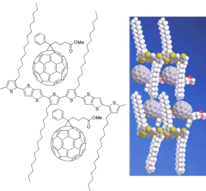
of the polymer with the PC61BM. This is explicitly shown by the poor performance of
poly(2,5-bis(3-hexadecylthiophen-2-yl)thieno[3,2-b]thiophene (pBTTT), which has wide spacing between the side chains
on the aromatic backbone.33 Intercalation of the PC71BM in between the side chains of the polymer requires
that significantly more PC71BM be used to create the optimal photovoltaic performance. Additionally,
intercalation causes increased recombination and a lower open circuit voltage due to increased interaction
of the polymer with the fullerene in the ground state. Therefore, the aromatic units must have places to
Figure 1.15. PCBM intercalates into pBTTT inhibiting phase segregation, reducing the open circuit
voltage, and promoting recombination. Intercalation between the side chains of P3HT is inhibited since the
space between them is significantly smaller. Reprinted with permission from ref. 35.
After correct selection and design of the aromatic units comprising the conjugated backbone, the
aliphatic solubilizing chains must be selected. Selecting the correct solubilizing chains is an optimization
problem between long chains which increase solubility and shorter ones which allow for more rapid hole
transport. One main method to achieve both of these goals simultaneously is to branch the side chain. Side
chain branching allows for an increased number of carbons to be attached while keeping the distance the
side chains protrude from the polymer backbone short. Shortening this distance increases the hole mobility
of the resulting polymer. In fact, since holes are transported along the polymer chain rapidly, only a few
µh= 2.6 × 10⁻⁴cm2V-1s-1
µh= 267 × 10-4cm2V-1s-1
A B
Figure 1.16. A) Both dithienopyrroles have 11 carbons in the aliphatic chain, however the branched chain
allows other polymer chains to pack closer, since the in-plane distance of the alkyl chain is shorter. B)
When 9,9-diisobutylfluorene is copolymerized with 9,9-dioctylfluorene, the hole mobility of the copolymer
increases by two orders of magnitude over poly(9,9-dioctylfluorene).34
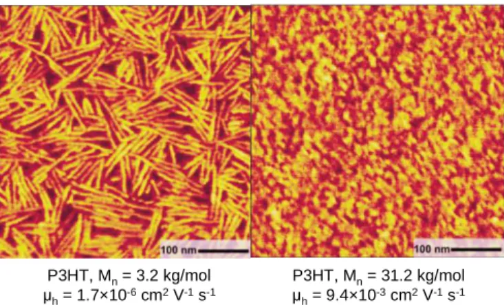
However, shorter chains only increase the hole mobility as long as the molecular weight of the
polymer material remains high. Decreasing the chain length can often cause a polymer to lose solubility
and precipitate during the polymerization, rather than reaching high molecular weight. The shorter polymer
chains do not make homogenous films, and can form crystalline domains. And while the hole mobility in
these crystalline domains is high, the grain boundaries in between each domain provide significant hole
transport barriers which cause the hole mobility of the bulk film to be significantly lower.35 This tendency
to form crystalline domains causes the photovoltaic performance to suffer as well, and therefore high
molecular weight polymer is critical to obtaining high photovoltaic performance.36,37
P3HT, Mn= 3.2 kg/mol
µh= 1.7×10⁻⁶cm2V-1s-1
P3HT, Mn= 31.2 kg/mol
µh= 9.4×10⁻³cm2V-1s-1
Figure 1.17. Low molecular weight P3HT (left) forms partially crystalline films, with large grain
boundaries. These grain boundaries reduce the hole mobility by over three orders of magnitude. Reprinted
State of the Art: 2006
When this dissertation was proposed in 2006, many of the concepts discussed in this introduction were
unknown or poorly understood. The polymer with the highest reported device efficiency was P3HT at
5%.38 No polymer with a band gap lower than 1.9 eV had achieved power conversion efficiencies over 2%.
The most successful low band gap conjugated polymer photovoltaic cells were reaching efficiencies of only
1%, likely due to the low molecular weight of the materials.39,40 However, many of the performance criteria
for these bulk heterojunction photovoltaic cells were just becoming understood. Therefore, this project was
initiated at precisely the right time. Our efforts focused on designing polymer materials which would
Chapter 2: Polycyclic Aromatics with Flanking Thiophenes:
Tuning Energy Level and Band Gap of Conjugated Polymers for
Bulk Heterojunction Photovoltaics
Adapted with permission from Macromolecules 2009, 43, 797.
By Samuel C. Price, Andrew C. Stuart, and Wei You
In PC61BM based BHJ solar cells, the theoretical maximum Voc of a device is determined by
highest occupied molecular orbital (HOMO) energy level of the conjugated polymer, and the theoretical
maximum Jsc of a device is largely dependent on the band gap of this conjugated polymer.41 The most
successful low band gap polymer design strategy to date for photovoltaic devices is the donor-acceptor
alternating copolymer (or intramolecular charge transfer copolymer) strategy, which has produced several
polymers with photovoltaic power conversion efficiencies larger than 4.0%.42-51 The HOMO level of these
donor-acceptor copolymers is determined almost exclusively by the donor monomer.52,53 In order to
decrease the HOMO level (and raise the Voc of the resulting photovoltaic cell), donors with “weaker”
electron donating ability should be applied to this strategy. However, while “weaker” donors will improve
the Voc by lowering the HOMO, they will also widen the band gap since the interaction between the
electron rich donor and the electron poor acceptor is what lowers the band gap of these copolymers.
Additionally, polymers with HOMO levels below – 5.9 eV exhibit higher rates of geminate charge
recombination.54 Thus, finding an optimal donor monomer which maximizes the photovoltaic efficiency is
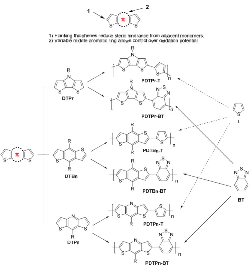
To systematically discover this optimal donor monomer, a design strategy based upon fusing
aromatic rings of different oxidation potentials into bithiophene was envisioned. First, bithiophenes
flanking a center aromatic ring was chosen as a template, since fused thiophenes have produced several
high mobility polymers, and the flanking thiophenes would reduce steric hindrance and create smaller
dihedral angles with adjacent monomers. Then pyrrole, benzene, and pyridine were inserted into the
bithiophene template to create three donor monomers of decreasing electron donating ability. These three
monomers were then copolymerized with 2,1,3-benzothiadiazole and with thiophene in order to study the
optical, electronic, photovoltaic properties of these polymers, and to identify the most promising monomer
for future study.
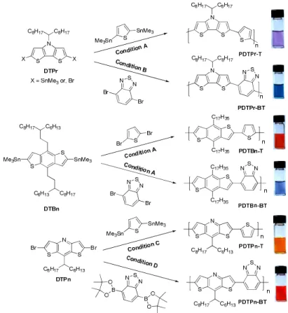
Figure 2.18. The library of structurally related polymers. “DT” stands for dithiophene. “Pr”, “Bn” and
“Pn” stand for fused pyrrole, benzene, and pyridine, respectively. “T” for thiophene, and “BT” for
Monomer and Polymer Synthesis
Two structural units, dithieno[3,2-b:2',3'-d]pyrrole (DTPr)55,56 and benzo[1,2-b:4,5-b']dithiophene
(DTBn),57 were synthesized according to literature procedures. Long branched alkyl chains were attached
in the center pyrrole or benzene unit to ensure the solubility of resulting polymers. Both units were readily
converted into distannylated monomers to co-polymerize with dibrominated co-monomers via Stille
coupling polymerization, offering corresponding polymers (Figure 1). The third structural unit,
dithieno[3,2-b:2',3'-e]pyridine (DTPn), has also been reported in the literature.58 However, in our efforts to
synthesize dithienopyridines with long solubilizing alkyl chains, we encountered a great deal of difficulty
with the established synthetic route.58 The literature procedure employed a bromination (Figure 1A) in the
final steps of the synthesis, which offered the target molecules with very low yield when long alkyl chains
were involved (6% when R = n-dodecyl).59 With our particular substrates which possessed a more bulky
alkyl chain at the 8 position of the DTPn, the reported bromination procedure resulted in either inseparable
mixtures, or exceptionally low yields.
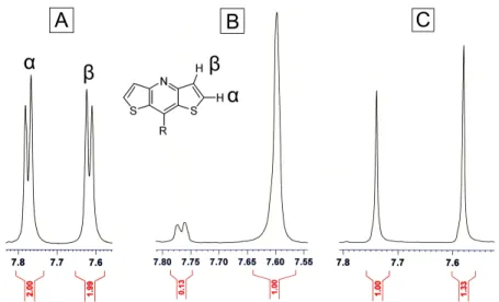
The distannyl intermediate of the literature bromination procedure could also serve as a
polymerizable monomer for Stille coupling polymerization, however, metalation of (1) with n-BuLi
according to the literature procedure resulted in a mixture of monostannyl and distannyl compounds which
could not be separated. In an attempt to optimize the stannylation procedure, (1) was lithiated with n-BuLi
then quenched with deuterated methanol (Figure 19B). This deuterium labeling experiment reveal that
even after 5 hours, the lithiation was not complete, and some starting material remained according to NMR
(Figure 20). Attempts to optimize the metalation procedure using tert-BuLi resulted in complete
deprotonation with no traces of starting material; however the deprotonation was not selective, resulting in
a 57:43 mixture of α:β deprotonation. Therefore, a new synthetic route to prepare polymerizable
Figure 2.19. (A) Literature procedure to synthesize the dibrominated DTPn. (B) Deuterium labeling
experiment. (C) Modified synthetic procedure of dibrominated DTPn.
Due to these deficiencies with the literature preparation, a modified synthetic scheme (Figure 19C)
that introduced a bromine in the α position of the thiophene before condensation to form the pyridine ring
was envisioned. The bromine was introduced in the first step by bromination of the commercially available
thiophene-3-carboxylic acid.60 The acid (2) was then subjected to a Curtius rearrangement to produce the
Boc protected amine (3) in good yield. The Boc protecting group stabilized the easily oxidized amine, and
was readily deprotected in situ in the subsequent acid catalyzed condensation step. The aldehyde (4) was
chosen to ensure the good solubility of the resulting polymers. The TFA catalyzed condensation then
afforded the final monomer (5) as a solid, which would aid in preparing high molecular weight polymers
from typical condensation polymerizations where rigorous control of stoichiometry is required. This
monomer (5) was then copolymerized with 2,5-bis(trimethyltin)thiophene or
2,1,3-benzothiadiazole-4,7-bis(boronic acid pinacol ester) to offer the desired polymers, PDTPn-T and PDTPn-BT.
Figure 2.21. Synthesis of polymers via palladium catalyzed coupling reactions. Shown on the right are
The crude copolymers were washed extensively with methanol, followed by the Soxhlet extraction
with methanol, and ethyl acetate successively to remove byproducts and oligomers. Finally, the polymers
were extracted by hexane or chloroform and re-collected by precipitating them into methanol, and dried
under vacuum. The molecular structures of both polymers were confirmed by 1H NMRspectroscopy. The
yields, molecular weights, and degree of polymerization of polymers are listed in Figure 2.22. The low
yield of PDTPr-T can be attributed to its low solubility, as large quantities of solid remained in the Soxhlet
extraction thimble after chloroform extraction. The opposite problem explains the low polymer yield for
PDTBn-BT, in that a large quantity of material was collected in the hexane fraction of the polymerization.
However, this hexane fraction consisted of low molecular weight polymer, and only the high molecular
weight chloroform fraction was used, decreasing the polymerization yield significantly. The molecular
weights were determined by gel permeation chromatography (GPC) in THF or 1,2,4-trichlorobenzene by
referring to polystyrene standards (Figure 22). The molecular weights of DTPn based polymers (PDTPn-T
and PDTPn-BT) are noticeably low, which can be attributed to their lower solubility during the
polymerization reaction.
Figure 2.22. Polymerization results for all six polymers
Yield Mn Mw Xn
[%] [kg/mol] [kg/mol]
PDI
PDTPr-T 13% 12.2 a 50.3 a 24.5 4.1
PDTPr-BT 63% 8.0 b 17.6 b 14.5 2.20
PDTBn-T 93% 54.1 b 109.6 b 85.2 2.02
PDTBn-BT 8% 69.9 b 150.7 b 97.5 2.15
PDTPn-T 90% 4.3 a 10.7 a 8.9 2.47
PDTPn-BT 76% 1.5 a 2.6 a 2.8 1.68
a Determined by GPC in 1,2,4-trichlorobenzene using polystyrene standard at 150 °C. b Determined by
Optical and Electrochemical Properties
This collection of structurally similar yet energetically diverse polymers allows for the interplay
between the electron donating ability of the donor monomer and the optical and electronic properties to be
studied in detail. The optical and electrochemical properties of these polymers are summarized in Figure
2.26.
Interestingly, the HOMO energy level of the entire conjugated polymer is dominated primarily by
the most electron rich aromatic unit in the polymer, regardless of what other rings it is fused to. For
example, nearly identical HOMO levels of – 4.89 eV and – 4.94 eV were observed in T and
PDTPr-BT respectively, because the most easily oxidized ring in these two polymers is the pyrrole ring.
Therefore, the monomer DTPr is polymerized with (BT or T) has little effect on the HOMO energy level,
and this phenomena is common with other polymer systems.61 However, when the pyrrole ring is
substituted for a benzene or pyridine ring, a drastic reduction in the HOMO energy level is observed. Since
the newly substituted benzene or pyridine ring is no longer the most electron rich ring in the system, the
HOMO is relatively independent of which ring is substituted for the pyrrole ring. For example, nearly the
same HOMO energy levels (– 5.55 eV vs. – 5.56 eV) are measured for PDTBn-BT and PDTPn-BT. This is
because the HOMO behavior is dominated by the two flanking thiophene rings. The same trend is apparent
in the case of PDTBn-T and PDTPn-T, as the HOMO behavior is dominated by the copolymerized
thiophene ring and causes the HOMO position to be roughly equal for both polymers despite their
structural differences.
-3 -2 -1 0 1 2
Potential vs.Fc/Fc+ (V)
PDTPr-T PDTPr-BT PDTBn-T PDTBn-BT PDTPn-T PDTPn-BT 100µ A
Despite the HOMO energy level depending greatly on the most electron rich ring in the aromatic
system, the optical band gap involves the entire polymeric system. Even though the HOMO energy level of
the DTPn polymer series is little changed from the DTBn series, the band gaps of the DTPn series are
significantly wider than these of the DTBn series. For example, the band gap of PDTPn-BT (2.1 eV) is
noticeably larger than that of PDTBn-BT (1.8 eV), due to the electron deficient pyridine, which diminishes
the donor-acceptor interaction in the copolymer that gives the low band gap.
400 500 600 700 800 900 0.0
0.2 0.4 0.6 0.8
1.0 PDTPr-BT
PDTPr-T PDTBn-BT PDTBn-T PDTPn-BT PDTPn-T N o rm a li z e d A b s o rp ti o n Wavelength (nm) (A)
400 500 600 700 800 900 1000 0.0 0.2 0.4 0.6 0.8 1.0
1.2 PDTPr-BT PDTPr-T
PDTBn-BT PDTBn-T PDTPn-BT PDTPn-T N o rm al iz ed A b so rb an ce Wavelength (nm) B
Figure 2.24. (A) Solution absorption of all polymers in chloroform. (B) Film absorption spectra.
400 450 500 550 600 650
0.0 0.1 0.2 0.3 0.4 0.5 0.6 N or m a li z e d A bs or ba nc e Wavelength (nm) PhCl R.T. Film on Glass Hot PhCl
PDTBn-T
Figure 2.25. UV-Vis spectra of PDTBn-T in boiling chlorobenzene, the same solution at room
Based on electrochemical and optical considerations alone, DTBn is the most promising candidate
for use in photovoltaic devices. The low measured HOMO energy levels predict high values of the Voc, and
the measured optical band gap remains low. Conversely, these results exhibit the DTPn and DTPr units less
favorably as possible successful candidates for use in photovoltaic devices. The band gaps of polymers
made from the DTPn donor unit are significantly wider than the others in this study, while the HOMO
levels are almost identical to the HOMO levels of the DTBn series. While polymers based upon DTPr have
large theoretical maximum currents due to their lower band gaps, the HOMO levels of this series of
polymers remains too high to yield devices with high efficiencies.
Figure 2.26. Optical and electrochemical data of all polymers
UV-Vis Absorption Cyclic Voltammetry
CHCl3 solution Film
ox onest
E
(V) red onestE
(V)polymer λmax
[nm]
λonset
[nm]
Ega
[eV]
λmax
[nm]
λonset
[nm]
Ega
[eV] HOMO [eV] LUMO [eV]
PDTPr-T 575 659 1.9 609 663 1.9 0.09/– 4.89 – 2.24/– 2.56
PDTPr-BT 697 837 1.5 727 875 1.4 0.14/– 4.94 – 1.73/– 3.07
PDTBn-T 537 566 2.2 543 584 2.1 0.55/– 5.35 – 2.18/– 2.62
PDTBn-BT 648 688 1.8 650 694 1.8 0.75/– 5.55 – 1.55/– 3.25
PDTPn-T 465 535 2.3 465 534 2.3 0.63/– 5.43 – 1.83/– 2.97
PDTPn-BT 508 580 2.1 540 579 2.1 0.76/– 5.56 – 1.47/– 3.33
a Calculated from the intersection of the tangent on the low energetic edge of the absorption spectrum with
the baseline.
Photovoltaic Properties
These structurally similar, yet optically and electrochemically very different polymers were tested
in bulk heterojunction photovoltaic devices. Standard BHJ device configuration was used
employed to simulate the irradiation from the Sun. The blending ratio of polymer vs. PCBM and the
thickness of the active layer were varied to achieve the best device performance under semi-optimized
conditions (Figure 2.28). Representative J-V curves of these polymers under 1 Sun condition are displayed
in Figure 2.27.
0.0 0.2 0.4 0.6 0.8 1.0 -4 -2 0 2 4 6 8 10 C u rr e n t D e n s it y ( m A /c m 2 ) Voltage (V) PDTPr-T PDTPr-BT PDTBn-T PDTBn-BT PDTPn-T PDTPn-BT
Figure 2.27. Characteristic I-V curves of the optimized devices of all polymers based BHJ solar cells under
1 Sun condition.
Figure 2.28. Photovoltaic performance of polymers
Polymer Polymer: PCBM Thickness (nm) Voc (V) Jsc
(mA/cm2) FF
η
(%)
IPCE
(%)
Rs
(Ω)
PDTPr-T 1:1 50 0.29 1.89 0.32 0.18 0.58 117
PDTPr-BT 1:3 100 0.46 4.0 0.39 0.72 33.1 78
PDTBn-T 1:2 190 0.88 2.17 0.54 1.02 8.62 147
PDTBn-BT 1:1 155 0.77 3.02 0.41 0.94 16.1 80
PDTPn-T 1:3 50 0.41 1.93 0.34 0.27 10.1 48.7
PDTPn-BT 1:1 45 0.31 0.75 0.37 0.09 5.16 80
The PDTBn series immediately exhibits superior photovoltaic properties when compared to the
rest of the polymers in this study. The theoretical predicted Voc of 0.95 V and 0.75 V for PDTBn-BT and
surprisingly, the lower HOMO of the polymers (e.g. PDTBn-BT) yields relatively higher Voc values. The
moderately low band gaps in the DTBn series are sufficient to produce satisfactory short circuit currents.
Additionally, the symmetrical nature of the monomer combined with the alkyl chain branching being
located on a carbon that is not adjacent to the polymer backbone should yield polymers films with
increased π stacking. Thus despite a wider band gap, the high molecular weight causes the short circuit
current of the DTBn series to be very close to that of the DTPr series of polymers.
450 500 550 600 650 700 750 800 0.0 0.1 0.2 0.3 0.4 0.5 0 5 10 15 20 PDTBn-BT A b s o rb a n c e ( a . u .) Wavelength (nm) E Q E ( % )
Figure 2.29. IPCE spectrum of BHJ photovoltaic device of ITO/PEDOT:PSS (45nm)/PDTBn-BT:PCBM
(1:1, w/w)/Ca (30nm)/Al (100nm) and the optical absorptions for the corresponding film of the blend.
As predicted, the low Voc of the polymers in the DTPr series remains the limiting factor in their
solar cell performance, with both cells recording Voc values lower than 0.5 V. PDTPr-BT’s especially low
band gap does lead to a 32% increase in the Jsc compared with that of PDTBn-BT, however, a significantly
higher current must be obtained in order to offset its low Voc (0.46 V) and Fill Factor (0.39). While these
parameters can be improved by increases in molecular weight and further optimizing the polymer structure
(modifying the alkyl chain length, varying the acceptor other than BT, etc.), the D-A polymers based on
DTPr are intrinsically limited by their high lying HOMO energy levels. Therefore DTPr is not a
particularly promising candidate for constructing new polymers as high efficiency photovoltaic materials.
However, applications which require especially low band gaps (for example, infrared detectors) are still a
possibility for this electron rich donor monomer.
The DTPn series does not behave as expected in terms of Voc. The experimentally determined
values are significantly lower than the Voc expected given the low HOMO levels of the polymers in this
a degree of polymerization of 2.25, and the effects of low molecular weight on all aspects of solar cell
performance are well documented. 36,37,65,66 Additionally, the large branched alkyl chain adjacent to the
polymer backbone in the DTPn (and DTPr) series could lead to polymers that do not π stack strongly,
which would reduce the efficiency of charge transportation in the BHJ device. However, further
optimization of the polymer structure was not warranted given the poor energetic and optical properties of
this series of polymers.
Figure 2.30. Mobility measurements for pure film, and polymer:PCBM composites
Polymer Pure Polymer
Thickness (nm)
Mobility (cm2 V-1 s-1)
Polymer: PCBM
Thickness (nm)
Mobility (cm2 V-1 s-1)
PDTPr-T 130 1.11 × 10⁻⁵ 1:1 75 8.17 × 10⁻⁶
PDTPr-BT 120 6.41 × 10⁻⁵ 1:3 75 1.15 × 10⁻⁵
PDTBn-T 80 2.57 × 10⁻⁵ 1:2 65 2.14 × 10⁻⁶
PDTBn-BT 105 2.75 × 10⁻⁵ 1:1 240 3.88 × 10⁻⁷
PDTPn-T 60 5.98 × 10⁻⁶ 1:3 45 3.55 × 10⁻⁶
PDTPn-BT 100 5.35 × 10⁻⁶ 1:1 45 2.25 × 10⁻⁶
The relative low efficiencies of these polymer based BHJ devices are mainly due to their low
current, though low band gaps have been achieved in some of these polymers (e.g. PDTPr-BT and
PDTBn-BT). In addition to a low band gap, a high hole mobility, comparable to the electron mobility of PCBM, is
also required to achieve a high current. The hole mobility of these polymers in the BHJ blends was
calculated via the space-charge limited current (SCLC) model by constructing hole-only devices with 40
nm of palladium (see experimental section for more details)67. For comparison, “polymer only” devices
were also fabricated to probe the mobility of polymers in the absence of PCBM.68 The measured hole
mobilities of these polymers in the absence of PCBM are generally much lower than the electron mobility
of PCBM (~10-4 cm2/V·s) (Figure 2.30), which explains the low efficiencies of these devices when
compared with P3HT and other high performance polymers. Additionally, the film morphology of these
devices is not optimal. For example, AFM images of PDTBn-T based devices reveal micron sized phase
segregation (even though PDTBn-T based devices exhibited the highest efficiency). Thus, these devices
techniques beyond simple device thickness and ratio of polymer:PCBM could allow for an increase in
device performance.
Figure 2.31. Atomic Force Microscope (AFM) images of PDTBn-T:PCBM film in a 1:2 ratio blend.
Observed micron sized phase segregation is not optimal for bulk heterojunction performance (left: height
image; right: phase image).
A collection of 6 electrochemically and optically unique polymers based upon three donor
monomers were investigated. All three donor monomers are structurally related, featuring same flanking
thiophenes, but incorporating different center aromatic units. DTBn based polymers exhibited the most
potential in photovoltaic applications due to its moderately low band gap, and low HOMO energy level.
The other polymers in this study either demonstrated high lying HOMO energy levels (DTPr based
polymers), or unacceptably wide band gaps (DTPn based polymers).
Two key structure/property trends have also emerged. The behavior of the HOMO energy level is
dominated by the most electron rich ring in the polymer backbone. Conversely, the optical band gap is a
function of the electronic properties of the entire conjugated aromatic backbone. Electron deficient pyridine
diminishes the donor-acceptor interaction in the copolymer that gives the low band gap. This explains the
0.3 eV change in the band gap between DTBn-BT and DTPn-BT, and the 0.3 eV change in band gap
between DTBn-T and DTPr-T.
The best donor monomer candidate in this study is the DTBn monomer unit. Key advantages are
The photovoltaic performance of DTBn polymer series is largely inhibited by the low hole mobility of the
two polymer candidates. Future study will focus on improving the hole mobility of these polymers in order
to improve their photovoltaic performance.
Experimental Section
General Methods: 1H nuclear magnetic resonance (NMR) spectra were obtained at 400 MHz or
300 MHz as solutions in CDCl3. 13C NMR spectra were obtained at 100 MHz as solutions in CDCl3.
Chemical shifts are reported in parts per million (ppm, δ), and referenced from tetramethylsilane. Coupling
constants are reported in Hertz (Hz). Spectral splitting patterns are designated as s, singlet; d, doublet; t,
triplet; m, multiplet; br, broad. Melting points are uncorrected.
UV-visible absorption spectra were obtained by a Shimadzu UV-2401PC spectrophotometer.
Fluorescence spectra were recorded on a Shimadzu RF-5301PC spectrofluorophotometer. For the
measurements of thin films, the polymer was spin-coated @ 600 RPM onto pre-cleaned glass slides from
10 mg/mL polymer solution in o-dichlorobenzene, and dried slowly in a petri dish for 3 hours.
Gel permeation chromatography (GPC) measurements were performed on two different machines,
depending upon the solubility of the polymers in THF. For THF soluble polymers, a Waters 2695
Separations Module apparatus with a differential refractive index detector (at UNC Chapel Hill) was used,
employing tetrahydrofuran (THF) as the eluent. For THF non-soluble polymers, a Polymer Laboratories
PL-GPC 220 instrument (at University of Chicago) was used, using 1,2,4-trichlorobenzene as the eluent
(stabilized with 125 ppm BHT) at 135°C. The obtained molecular weight is relative to polystyrene
standards.
Cyclic voltammetry measurements were carried out using a Bioanalytical Systems (BAS) Epsilon
potentiostat equipped with a standard three-electrode configuration. Typically, a three-electrode cell
equipped with a glassy carbon working electrode, a Ag/AgNO3 (0.01 M in anhydrous acetonitrile)
reference electrode, and a Pt wire counter electrode was employed. The measurements were done in
anhydrous acetonitrile with tetrabutylammonium hexafluorophosphate (0.1 M) as the supporting electrolyte
under an argon atmosphere at a scan rate of 100 mV/s. Polymer films were drop-cast onto the glassy carbon
measurements. The potential of Ag/AgNO3 reference electrode was internally calibrated by using the
ferrocene/ferrocenium redox couple (Fc/Fc+). The electrochemical onsets were determined at the position
where the current starts to differ from the baseline. The highest occupied molecular orbital (HOMO) and
lowest unoccupied molecular orbital (LUMO) energy levels were calculated from the onset oxidation
potential (Eox) and onset reductive potential (Ered), respectively, according to eqs 1 and 2.
Eq 1:
=
−
(
ox+
4
.
8
)
E
HOMO
(eV)Eq 2:
LUMO
=
−
(
E
red+
4
.
8
)
(eV)Polymer solar cell fabrication and testing: Glass substrates coated with patterned tin-doped
indium oxide (ITO) were purchased from Thin Film Devices, Inc. The 150 nm sputtered ITO pattern had a
resistivity of 15Ω/□. Prior to use, the substrates were ultrasonicated for 10 minutes in acetone followed by
deionized water and then 2-propanol. The substrates were dried under a stream of nitrogen and subjected to
the treatment of UV-Ozone over 20 minutes. A filtered dispersion of PEDOT:PSS in water (Baytron
PH500) was then spun cast onto clean ITO substrates at 4000 rpm for 60 seconds and then baked at 140 °C
for 10 minutes to give a thin film with a thickness of 40 nm. A blend of polymer and PCBM (1:1, 1:2 or
1:3, w/w, depending upon the polymer, see Table 3) at 10 mg/mL (for polymer) was dissolved in
dichlorobenzene (for PDTPr-BT) or chlorobenzene (for other polymers) with heating at 60 °C for 6 hours,
filtered through a 0.45 µ m poly(tetrafluoroethylene) (PTFE) filter, and spun cast between 800 – 1200 rpm
for 60 seconds onto a PEDOT:PSS layer. The substrates were then dried at room temperature under N2 for
12 hours. The devices were finished for measurement after thermal deposition of a 30 nm film of calcium
and a 100 nm aluminum film as the cathode at a pressure of ~ 1 × 10⁻⁶ mbar. There are 8 devices per
substrate, with an active area of 12 mm2 per device. The thicknesses of films were recorded by a
profilometer (Alpha-Step 200, Tencor Instruments). Device characterization was carried out under AM
1.5G irradiation with the intensity of 100 mW/cm2 (Oriel 91160, 300 W) calibrated by a NREL certified
standard silicon cell. Current versus potential (I-V) curves were recorded with a Keithley 2400 digital
source meter. EQE were detected under monochromatic illumination (Oriel Cornerstone 260 ¼ m
monochromator equipped with Oriel 70613NS QTH lamp) and the calibration of the incident light was
performed with a monocrystalline silicon diode. All fabrication steps after adding the PEDOT:PSS layer
mobility measurements, the hole-only devices in a configuration of ITO/PEDOT:PSS (45
nm)/polymer-PCBM/Pd (40 nm) were fabricated. The experimental dark current densities J of polymer: PCBM blends
were measured when applied with voltage from 0 to 6 V. The applied voltage V was corrected from the
built-in voltage Vbiwhichwas takenas a compensation voltage Vbi=Voc + 0.05 V and the voltage drop Vrs
across the indium tin oxide/poly(3,4-ethylene-dioxythiophene):poly(styrene sulfonic acid)
(ITO/PEDOT:PSS) series resistance and contact resistance, which is found to be around 35 Ω from a
reference device without the polymer layer. From the plots of J 0.5 vs. V(supporting information), hole
mobilities of copolymers can be deduced from
3 2 0
8
9
L
V
J
=
ε
rε
µ
hwhere ε0 is the permittivity of free space, εr is the dielectric constant of the polymer which is assumed to be
around 3 for the conjugated polymers, µh is the hole mobility, V is the voltage drop across the device, and L
is the film thickness of active layer.
Reagents: All solvents are ACS grade unless otherwise noted. Anhydrous THF was obtained by
distillation from sodium/benzophenone prior to use. Anhydrous methylene chloride was dried over
magnesium sulfate and filtered directly into the reaction flask prior to use. Anhydrous toluene was used as
received. Anhydrous tert-butanol was obtained by treatment with sodium metal and then distillation.
2-bromothiophene-4-carboxylic acid,60
2,6-di(trimethyltin)-N-(1-octylnonyl)dithieno[3,2-b:2',3'-d]pyrrole,55 2,5-bis(trimethyltin)thiophene,69 4,7-dibromo-2,1,3-benzothiadiazole, 70 and
2,1,3-benzothiadiazole-4,7-bis(boronic acid pinacol ester)71 were prepared according to established
literature procedures. 2,6-Bis(trimethyltin)-4,8-(3-hexylundecyl)benzo[1, 2-b:4,5-b']dithiophene,49,57 and
N-(1-octylnonyl)-2,6-dibromodithieno[3,2-b;2',3'-d]pyrrole72,73 were prepared using procedures analogous
to established literature procedures and 1H and 13C NMR spectra are exhibited below for these monomers.
All other chemicals were purchased from commercial sources (Acros, Alfa Aesar, Aldrich, Fisher
tert-butyl 5-bromothiophen-3-ylcarbamate (3): 2-bromothiophene-4-carboxylic acid (11.584g, 55.95
mmol) was combined with anhydrous toluene (225 mL) in a dry flask under argon. Triethylamine (11.8
mL, 83.93 mmol) was added to the slurry, which became homogeneous after addition. Diphenylphosphoryl
azide (12.1 mL, 55.95 mmol) was then added at room temperature, and the reaction mixture was stirred for
2.5 hours. The mixture was then heated to 80°C, and stirred for 1 hour. Anhydrous tert-butanol (16.0 mL,
167.9 mmol) was then added, and the reaction mixture was stirred for 16 hours at 80°C. The mixture was
then concentrated, and purified by column chromatography using a 3:2 toluene:hexanes solution as the
eluent. The fractions were concentrated, affording a beige powder of sufficient purity for the following
steps. Yield: 11.807g (76%). Analytical purity was obtained by recrystallization from cyclohexanes
(refluxed, then cooled to 4°C), yielding colorless prisms which were stable in atmosphere for over a week.
Colorless crystalline solid; m.p. 88-91°C. 1H NMR (CDCl3, 300 MHz, δ): 7.04 (br s, 1H), 6.94 (br s, 1H),
6.61 (br s, 1H), 1.50 (s, 9H). 13C NMR (CDCl3, 100 MHz, δ): 152.5, 135.8, 123.7, 111.7, 108.7, 80.9, 28.2.
ESI-TOF MS: [M+Na]+ = 299.9667 (calcd [M+Na]+ = 299.9670).
N
S S
Br Br
2,6-dibromo-8-(1-hexylnonyl)dithieno[3,2-b:2',3'-e]pyridine (5): 3 (2.039 g, 7.33 mmol), and
2-hexyldecanal (881 mg, 3.67 mmol) were dissolved in methylene chloride (40 mL). Trifluoracetic acid
(1.8 mL) was slowly added over 3 minutes, and the resulting mixture was heated to reflux. After 18 hours,
the reaction mixture was partitioned between CH2Cl2 and ice cold 10% NaOH solution, separated, and the
organic layer was dried over Na2SO4. The mixture was then purified by column chromatography eluting
with a 7:1 mixture of hexanes:ethyl acetate. The resulting yellow oil was then concentrated under vacuum
(0.5 mmHg) for 24 hours, resulting in a pale brown solid. Yield: 615 mg (30%). Brown solid; m.p.
60-61°C. 1H NMR (CDCl3, 300 MHz, δ): 7.57 (s, 2H), 2.99 (m, 1H), 2.01 (m, 2H), 1.84 (m, 2H), 1.16 (m,
31.72, 31.49, 29.48, 29.19, 29.10, 27.79, 22.55, 22.48, 13.99, 13.91. ESI-TOF MS [M+H]+ = 558.0506
(calcd [M+H]+ = 558.0499).
2-hexyldecanal (4): Dimethylsulfoxide (10.2 mL, 143.6 mmol) was dissolved in anhydrous methylene
chloride (350 mL), and chilled to -78°C under argon. Oxalyl chloride (6.48 mL, 75.6 mmol) was then
slowly added dropwise, while maintaining the temperature at -78°C. The mixture was stirred for 30 min,
and then 2-hexyldecan-1-ol (20.9 mL, 71.99 mmol) was added dropwise at -78°C. The mixture was stirred
for 35 minutes carefully maintaining -78°C. TEA (30 mL, 215 mmol) was added, and a thick white
precipitate formed. The mixture was stirred for 10 minutes at -78°C, and then allowed to warm to room
temperature. The mixture was poured into 1M HCl, and extracted with methylene chloride. The organic
layer was then washed repeatedly with distilled water, and dried over MgSO4. The mixture was then
filtered, concentrated, and filtered through a short plug of silica gel. The silica gel was washed with
hexanes, and the filtrate was concentrated and distilled under reduce pressure. The desired aldehyde was
obtained at a distillate temperature of 105°C @ 0.6 mmHg. Yield: 12.087g (70%). Colorless oil; 1H NMR
(CDCl3, 300 MHz, δ): 9.55 (d, J = 3.3 Hz, 1H), 2.21 (m, 1H), 1.60 (m, 2H), 1.45 (m, 2H), 1.27 (m, 20H),
0.88 (t, J = 6.6 Hz, 6H). 13C NMR (CDCl3, 100 MHz, δ): 205.45, 51.94, 31.80, 31.59, 29.66, 29.35, 29.32,
29.18, 28.88, 27.03, 26.99, 22.59, 22.52, 14.00, 13.95.
Deuterium Lithiation Experiments: The following lithiation conditions are reproduced from
Macromolecules 2004, v. 37, p. 710. 1 (151 mg, 0.363 mmol) was dissolved in 1.5 mL of anhydrous THF
in a dry flask. The solution was cooled to -78°C, and a 2.5M solution of n-BuLi in hexanes (0.35 mL, 0.87
mmol) was added dropwise. The solution was stirred at -78°C for 1 hour, and then at 0°C for 5 hours. The
solution was then cooled back down to -78°C, and methanol-D4 (0.5 mL) was added in one portion. The
solution was stirred at -78°C for 5 minutes, and then warmed to room temperature. The reaction mixture
resulting filtrate was then concentrated, and the residue was analyzed by NMR. The procedure was
repeated using 2.05 equivalents of t-BuLi @ -78°C for 1 hour, and then quenching with methanol-D4.
Representative Stille Coupling Polymerization Procedure:
2,6-Bis(trimethyltin)-4,8-(3-hexylundecyl)benzo[1,2-b:4,5-b]dithiophene (498 mg, 0.502 mmol), 4,7-dibromo-2,1,3-benzothiadiazole
(147 mg, 0.502 mmol), tri(o-tolyl)phosphine (18 mg, 0.06 mmol), and 25 mL of anhydrous toluene were
combined, and purged with argon for 20 minutes. Then tris(dibenzylideneacetone)dipalladium(0) (7 mg,
7.53×10⁻³ mmol) was added under a stream of argon, and the reaction mixture was purged for an additional
15 minutes. The mixture was then heated to reflux, and stirred for 72 hrs. The reaction mixture was then
precipitated into methanol, and filtered into an extraction thimble. The polymer solids were then Soxhlet
extracted with methanol, ethyl acetate, hexanes, and chloroform. The chloroform extracts were then
concentrated, and precipitated into methanol. The resulting solids were filtered, washed with methanol,
and residual solvent was removed under vacuum at 0.5 mm Hg affording polymer PDTBn-BT as a
Chapter 3: Low band gap polymers based on
benzo[1,2-b:4,5-b
′
]dithiophene: rational design of polymers
leads to high photovoltaic performance
Adapted with permission from Macromolecules 2010, 43, 4609
By Samuel C. Price, Andrew C. Stuart, and Wei You
In the previous study, benzo[1,2 b:4,5 b′]dithiophene (BnDT) emerged as the most promising
donor candidate for intramolecular charge transfer copolymers. In an effort to further increase the power
conversion efficiency of these materials, BnDT based polymers have been designed to better fit the four
key design criteria41,74 that have emerged for the ideal candidate donor polymers to be used in BHJ devices
with fullerene as the acceptor: (a) a low HOMO energy level in order to achieve a high open circuit voltage
(Voc); (b) a low band gap to maximize light absorption; (c) a high hole mobility, which requires a planar
structure to encourage π stacking of the polymer chains; (d) a high molecular weight and good solubility, to
achieve the optimal morphology, in order to maximize the short circuit current (Jsc), and a high fill factor
(FF). Unfortunately, though numerous low band gap materials have been synthesized, only few polymers
have closely met all these criteria and demonstrated impressive efficiencies.43,45,51 In this study, a new
intramolecular charge transfer (ICT) copolymer,75,76 poly[4,8-dialkylbenzo[1,2-b:4,5-b′ ]dithiophene-alt-4,7-di(4-hexyl-2-thienyl)-2,1,3-benzothiadiazole] (PBnDT-4DTBT) was developed to fulfill these design
criteria. BHJ solar cells based on the blend of this polymer and PC61BM demonstrated a Voc of 0.81 V, a Jsc
of 9.70 mA cm-2, and a FF of 0.55, yielding an overall efficiency of 4.3% under 1 Sun condition (AM1.5,
100 mW cm-2). To the best of our knowledge, PBnDT-4DTBT:PC61BM demonstrates one of the highest
efficiencies achieved so far, under 1 sun conditions, by BHJ solar cells comprised of any single low band