Optimal Core–Edge Storage Area
Network Design
Timothy David Thompson
Supervised by Dr. M. O’Sullivan and Dr. C. Walker Department of Engineering Science
University of Auckland, New Zealand [email protected]
Abstract
Storage Area Networks (SANs) have become a unique solution for information man-agement as the integrity and reliability of data storage become increasingly impor-tant within industry. A SAN manages the transfer of data from sets of servers and/or clients to centralized data storage through an internal fabric comprising of switches, hubs and links.
Core-Edge is a reference topology widely used in the layout of SAN fabric. We study the problem of mapping this SAN fabric for specific demands, utilizing Core-Edge design. We present an integer programming (IP) model for this restricted network design problem and offer preliminary results and discussion on standards for Core-Edge SAN fabric design.
1
Introduction
Data management has developed into an important issue within industry as a conse-quence of increased dependency on electronic storage. With concerns for the security, reliability and availability of data within large-scale networks, companies are increas-ingly turning to centralized storage as a solution. Centralized storage permits data management to be externalized from the local computer network. This allows for better overall resource allocation and a reduction in complexity for administration and management of data. Multi-user access to the centralized storage is attained through the use of Storage Area Networks (SANs).
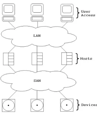
A SAN is a high-speed sub-network, secondary to a Local Area Network (LAN) or Wide Area Network (WAN). SANs manage the transfer of data from sets of servers and/or clients (hosts) to the centralized storage. The centralized storage incorporates media such as disks, disk arrays and tape drives (devices). The hosts and devices are connected through the internal fabric of the SAN comprising of
switches, hubs and links. Figure 1 illustrates the relationship between a SAN and LAN to connect each workstation to all attached devices. The arrangement of the LAN and SAN fabric is customized for the bandwidth requirements across both sub-networks.
Figure 1: Generalized network featuring a SAN
Industry shows that 10-20% of the total storage system cost can be attributed to the design and installation of the SAN (Ward et al. 2002). IT experts traditionally spend considerable time and effort manually designing SAN fabric for even small applications. Currently SANs can reach a size of 50 hosts and 100 devices (Ward et al. 2002). To minimize the installation and future cost of the SAN fabric, fabric planning such as network over-subscription and choice of design topology require appropriate consideration.
1.1 Core-Edge SAN Architecture
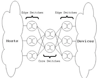
It is common practice for SAN designs to be based on reference topologies. Refer-ence topologies are adaptable structures that incorporate characteristics considered important in a network design. These topologies incorporate scalability, reliability and performance while minimizing the cost attributed to excess connection media. A number of reference topologies are available to aid in the design of SAN fabric. Core-Edge is a reference topology considered by many to be one of the most versatile forms of SAN design. This is illustrated by its wide application throughout industry. Core-Edge SAN designs are characterized by a symmetrical structure and a high level of scalability and reliability. A contemporary Core-Edge topology is formed around a set of high bandwidth director switches (coreswitches). Each core switch connects to all switches on an additional layer of lesser bandwidth (edge switches), which collectively connect all hosts and devices. The effective implementation of
Core-Edge design allows no host-device pair to be greater than four intermediate connections (hops) away from each other. Figure 2 illustrates a generalized Core-Edge SAN topology. This SAN utilizes a separate set of edge switches for hosts and devices. This is not always necessary, but we will refer to this specific form of Core-Edge topology here.
Figure 2: Generalized Core-Edge SAN design
Core-Edge SANs are easily configured to incorporate reliability and fault prevention. In Figure 2, two disjoint paths are formed between all pairs of edge switches. This is achieved through links connecting to/from these edge switches to both core switches. This can be extended with an effective connection plan to allow multiple independent paths between each host and device. If a fault was to occur within the network to disrupt a path between host and device, this connection remains active on the remaining independent paths.
The scaling of Core-Edge SANs can be achieved simply by the inclusion of additional edges switches (and core switches where required). This provides additional ports to connect host and/or devices to the network.
1.1.1 Link Over-Subscription
Link over-subscription is a practice common in network design that considers the cost benefit of merging multiple links into one. In the case of Core-Edge SANs, a link over-subscription ratio is defined as the ratio of total bandwidth entering an edge switch to total bandwidth leaving an edge switch in the direction of the core. The commercial standard for SAN links bandwidth is currently 1-2 Gb/s. In practice this bandwidth capacity is generally well beyond the instantaneous loading of a link. It is therefore considered a valid practice to employ link over-subscription within a SAN design to reduce the cost attributed to the SAN fabric. This is implemented in Core-Edge SANs using a maximum over-subscription ratio that each edge switch must not exceed. In industry this ratio is generally of order 7:1 (4:1 for high performance SANs).
1.2 Core-Edge SAN Fabric Design Problem Description
A related paper, (Ward et al. 2002), poses an integer programming (IP) formulation to a generalized SAN design problem. This problem involves finding an optimal arrangement of fabric components to simultaneously satisfy a set of bandwidth re-quirements between host and device pairs flows. In practice it is difficult to obtain
a priori knowledge of these flows. A more viable approach investigates connecting all hosts and devices at minimum cost.
The Core-Edge SAN fabric design problem involves finding an optimal Core-Edge arrangement of fabric components to connect all available host and device ports to the SAN at minimum cost. A resulting SAN design is to satisfy all port bandwidth requirements and not exceed a maximum link over-subscription.
The Core-Edge SAN fabric design problem is described in terms of hosts, devices, switch types, and link types.
A company has a set of hosts H that run applications which access data from a set of devices D. The hosts and devices have a fixed number of slots where ports are to be added. This means that a host h ∈ H or device d ∈ D may have no more thanη(h) or η(d) ports respectively. Each port available for host h (deviced) has a set bandwidth capacityβ(h) and cost π(h) (β(d) and π(d), respectively). An appropriate maximum over-subscription ratio (κ) is known for the SAN.
The number of switches and links are not knowna priori, however there exist sets of different switch typesS and link typesL. Each switch typet∈ S has an associated cost γ(t) and port cost π(t). Similarly each link type t ∈ L has costγ(t). We need to determine how many of each switch or link type to use and how to configure the network.
1.3 Previous Research
Commercial tools currently exist in industry that approach the problem described in Section 1.2. Hewlett-Packard (HP) laboratories currently have a heuristic tool for generating SANs with no set topology. This tool is capable of designing a SAN with 50 hosts and 100 devices, the size of the largest SANs in industry. One example from (Ward et al. 2002) shows that a heuristic tool of this nature can provide substantial savings over manual design ($1.4m versus $4m). For additional information we refer you to (Ward et al. 2002).
A limited number of tools are currently available that consider a specific topology, such as Core-Edge. One such tool is SANTK (Storage Area Network Toolkit) de-veloped by the University of Missouri to aid in the design of SAN fabric. SANTK incorporates a Core-Edge SAN design tool. This tool is algorithm-based and matches feasible switch and link arrangements to user-prescribed parameters. All Core-Edge SAN topologies are generateda prioriusing a limited set of switch types and a single link type.The designs generated by SANTK are limited to the circular Core-Edge topology, where all hosts and devices are connected to one set of edge switches. The algorithm considers only the number of ports required on the edge switches and provides no connection plan for linking the hosts and devices to these switches. For
additional information we refer you to (Strand 2002).
Problems of this nature can also arise in a variety of other fields. A problem de-fined by a set of transshipment demands with similar flow and node restrictions can be formulated in an identical manner to the Core-Edge SAN design problem. Such problems arise in contexts such as transportation networks, telecommunication networks, distributed computer networks, distribution systems and energy systems.
1.4 Outline
The rest of this paper is organized as follows. Section 2 summarize the IP formulation for the Core-Edge SAN design problem. We present preliminary results in Section 3 and compare the IP to similar tools currently available for Core-Edge design. Finally, in Section 4 we offer conclusions regarding the validity of our approach and outline any future work that is required.
2
Core-Edge SAN Model
The Core-Edge SAN design problem is an example of a restricted network design problem, a generalization of a known NP-hard problem. This problem considers the assignment of switches and links subject to degree, node and bandwidth constraints.
2.1 Switch and Link Sets
The switches are partitioned into three sets: host edge switches SH; device edge
switchesSD; and core switches SC (S =SH ∪SD∪SC). The nodesof the network are the hosts, devices and switches, i.e.,N =S∪ H ∪ D.
Each link l ∈ L has a source σ(l) ∈ N and a destination τ(l) ∈ N. The links are partitioned into 4 main sets: the links from hosts to host switches; the links from host switches to core switches; the links from core switches to device switches; and the links from device switches to devices. The second and third sets are partitioned further, so that there is a defined set of links between each host and core switch, and between each core and device switch. The sets of links are: LH between the hosts and host switches; L(h,c) between host switch h∈SH and core switch c∈SC; L(c,d)
between core switch c∈SC and device switch d∈SD; and LD between the devices switches and the devices. Therefore, the source and destination nodes for each set are restricted: σ(l) ∈ H, τ(l) ∈ SH for l ∈ LH; σ(l) = h, τ(l) = c for l ∈ L(h,c);
σ(l) = c, τ(l) = d for l ∈ L(c,d); σ(l) ∈SD, τ(l)∈ D for l ∈ LD. Note that we have defined enough links in LH (LD) to connect all the ports from any host (device, respectively) to any host switch (device switch, respectively).
2.2 Decision Variables
The primary decision variables for the Core-Edge SAN model are the existence of links and switches as well as their properties (bandwidth, number of ports, etc).
Given a candidate set of links Land switches S, we need to decide which links and switches to keep in the network. Define
us = 1 if we keep switchs ∈S vl = 1 if we keep link l ∈L
= 0 otherwise = 0 otherwise
Also, defineη(s) as the number of ports on switchs∈S;β(s) as the port bandwidth of ports on switch s∈S;β(l) as the bandwidth of ports on link l∈L.
Selecting Switch and Link Types Since switches and links are selected from pre-defined types (rather than configured independently) and their cost is deter-mined by these types, we need to select the appropriate type for each switch and link depending on their properties. This is done effectively by first creating two
technology tables. These tables define:
1. The least cost switch for all feasible pairs of number of ports and port band-width
2. The least cost link for all feasible bandwidths
Using these tables, the necessary master-slave constraints, and the variables
xst = 1 if switch s∈S is type t∈ S ylt = 1 if link l∈L is type t ∈ L
= 0 otherwise = 0 otherwise
nst = the number of ports of switch type t ∈ S on switchs ∈S
we can obtain the correct switch type and switch type ports for switches, and the correct link type for links. This in turn gives the correct cost for switches and links using only their properties. It is noted for s ∈ S if us = 0 then xst = 0 ∀t ∈ S. Similarly for l ∈ L if vl = 0 then ylt = 0 ∀t ∈ L. The details of the constraints needed to implement the technology table are omitted here for brevity. We refer you to (O’Sullivan, Walker, and Allard 2002) for further information.
For Core-Edge designs we need the same number of links between each host and core switch, defined here as a (non-negative) integer variablemH, and the same number of links between each core and device switch, defined here as a (non-negative) integer variablemD. We also need to ensure that we use the same link type between every host and core switch, and between every core and device switch, the variables
zH
t = 1 if we use link type t between the host and core switches, t ∈ S = 0 otherwise
ztD = 1 if we use link type t between the core and device switches, t ∈ S = 0 otherwise
2.3 Objective Function
The properties of the hosts and devices are known a priori. The properties of the switches and links determine their position on the technical table (and in the case of
switches the number of ports of any switch type). The total cost of the SAN fabric is Z = X s∈S,t∈S (γ(t)xst+π(t)nst) | {z }
switch and port cost
+ X l∈L,t∈L (γ(t)ylt) | {z } link cost + X l∈LH π(σ(l))vl | {z } host cost + X l∈LD π(τ(l))vl | {z } device cost 2.4 Node Constraints
The number of links leaving a host (entering a device) must be equal to the number of ports on that host(device, respectively). This means all host and device ports are connected by the SAN.
X l∈LH,σ(l)=h vl =η(h), h∈ H (1) X l∈LD,τ(l)=d vl =η(d), d∈ D (2)
The links leaving a host (entering a device) must have more bandwidth than the ports on the host (device, respectively). This ensures that the ports can be used to their maximum bandwidth capacity.
β(l)≥β(σ(l)), l ∈LH (3)
β(l)≥β(τ(l)), l ∈LD (4)
2.5 Switch Constraints
There are constraints for ordering switches within their sets, i.e., we will use the first switch inSH before the second, third, etc switches inSH. There are also constraint to remove antisymmetry amongst switches in the same set. These constraints require the earlier switches to have either more ports or the same ports and more port bandwidth than later switches.
The number of links attached to a switch must be less than the number of ports on the switch.
X
l∈L,σ(l)=sorτ(l)=s
vl ≤η(s), s∈S (5)
The port bandwidth of an edge switch must be more than the bandwidth of the links coming into the switch.
β(s)≥β(l), s∈SH, l ∈LH, τ(l) =s (6)
β(s)≥β(l), s∈SD, l∈LD, σ(l) =s (7)
The port bandwidth of a core switch must be more than the bandwidth of all links coming into the switch.
β(s)≥β(l), s∈SC, l ∈ ∪h∈SHL(h,s)
∪ ∪s∈SDL(s,d)
2.6 Architecture Constraints
There are constraints for link antisymmetry and ordering of links within their sets, similar to those defined for switches. These constraints require that earlier links have more bandwidth than later links.
The following constraints combine with the switch ordering constraints to ensure that the switch types remain constant over each of the switch sets. Note thats+ 1 means the next switch in the set.
xs+1t≤xst, s∈SH, except the last host switch (9)
xs+1t≤xst, s∈SD, except the last device switch (10)
xs+1t≤xst, s∈SC, except the last core switch (11)
The links within a link set have the same type or are not active. Note that l+ 1 means the next link in the set.
yl+1t ≤ylt, l ∈L(h,c), except the last link in each set (12)
yl+1t ≤ylt, l ∈L(c,d), except the last link in each set (13)
The following constraints combine with the link type ordering constraints (12) & (13) to ensure than the link types remain constant between active edge and core switches.
y1t≤ft+ (2−(uh+uc)), h∈SH, c∈SC, t∈ S (14)
y1t≥ft−(2−(uh+uc)), h∈SH, c∈SC, t∈ S (15)
y1t≤gt+ (2−(uc+ud)), c∈SC, d∈SD, t∈ S (16)
y1t ≥gt−(2−(uc+ud)), c∈SC, d∈SD, t∈ S (17)
The following constraints combine with the link ordering constraints to ensure the number of links between active edge and core switches remain constant.
X l∈L(h,c) vl ≤mH −M(2−(uh+uc)), h∈SH, c∈SC (18) X l∈L(h,c) vl ≥mH +M(2−(uh+uc)), h∈SH, c∈SC (19) X l∈L(c,d) vl ≤mH −M(2−(uc+ud)), c ∈SC, d∈SD (20) X l∈L(c,d) vl≥mH +M(2−(uc+ud)), c ∈SC, d∈SD (21)
3
Results
The IP introduced in this paper yields some clear advantages over the other tools available for Core-Edge SAN design. The most comprehensive tool currently avail-able in this field is SANTK, described in Section 1.3. The resultant SANs design
from the IP are optimal and including a full connection plan from all host to de-vices. These design properties are not available in current versions of SANTK. All functionality of the Core-Edge design tool in SANTK is encompassed within the IP. As a preliminary test for the Core-Edge IP, we apply the IP to a number of example problems of various magnitude. These example problems are presented in Table 2. The fabric sets available in each example includes 3 switch types and 2 link types as listed in Table 1. The hosts and devices are uniform, each including 2 available ports each with maximum bandwidth of 1 Gb. We apply a constant over-subscription ratio of 1:5 throughout.
Switch 1 2 3 Link 1 2
Port Number 8 16 32 Bandwidth (b) 1e8 5e7
Port Bandwidth (b) 1e8 1e8 1e8
Table 1: Example Problem Components
The IP is formulated in AMPL and solved using CPLEX 8.1 on a dual processor AMD Athlon MP 2200+ (1 Gb RAM) using Red Hat Linux 8.0. Figure 3 summaries the performance statistics for these example problems.
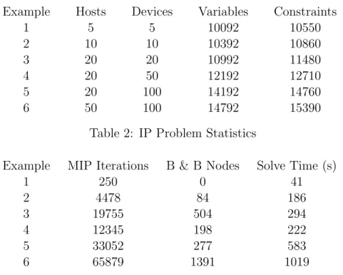
Example Hosts Devices Variables Constraints
1 5 5 10092 10550 2 10 10 10392 10860 3 20 20 10992 11480 4 20 50 12192 12710 5 20 100 14192 14760 6 50 100 14792 15390
Table 2: IP Problem Statistics
Example MIP Iterations B & B Nodes Solve Time (s)
1 250 0 41 2 4478 84 186 3 19755 504 294 4 12345 198 222 5 33052 277 583 6 65879 1391 1019
Table 3: IP Solution Statistics
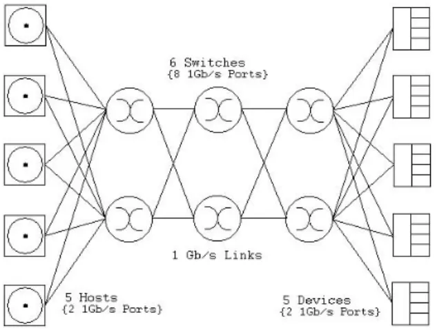
The scale of the examples considered in Table 2 have been selected to blanket the range of SANs currently in industry. The IP is observed to perform well for all cases. The solve time required to generate each SAN design is satisfactorily small and can be considered acceptable for a commercial tool of this nature. Example 6 is of equivalent magnitude to the largest SANs currently in operation in industry. This example solves in 1019 seconds, well within allowable bounds for a SAN design of this size. A less complex example of a Core-Edge SAN generated by the IP is illustrate in Figure 3. This design corresponds to example 2 described above in Table 2. This example solves in 186 seconds.
Further work is still required to test the IP on more diverse problems, incorporating additional fabric sets and less uniform host and device port arrangements. This is currently underway, however results are not available at this time. Also it would be useful to test the IP formulation on real world designs already implemented in industry. This would provide knowledge of cost effectiveness of the Core-Edge design and the potential of this tool.
Figure 3: Generalized Core-Edge SAN design
4
Conclusions
In this paper we introduce an IP formulation to a restricted network design problem considering Core-Edge SAN design. The IP approach yields some advantages over currently available tools in this area. The IP provides the user with an optimal SAN design with a full connection plan not currently available from Core-Edge design software.
The IP was applied to a selection of example problems encompassing the scale of SANs in commercial operation. The IP was found to perform well, producing solutions for all cases in an acceptable time-frame for a commercial tool. Further testing of the IP is, however, still required for more diverse networks. Also it would be advantageous to test the IP against implemented designs in industry to analyze the cost effectiveness of Core-Edge design.
References
O’Sullivan, M., C. Walker, and J. Allard. 2002, November. “Improving Optimal Storage Area Network Design.” ORSNZ Conference Twenty Naught Two. 119– 128.
Strand, S. 2002. “Storage Area Networks and SANTK.” Master’s thesis, University of Minnesota Fibre Channel.
Ward, J., M. O’Sullivan, T. Shahoumian, and J. Wilke. 2002, January. “Appia: Automatic Storage Area Network Design.” Conference on File and Storage Technology (FAST’02). 203–217.