ECE 35 Spring 2017
Homework #9 Solution
All homework problems come from the textbook, “Introduction to Electric Circuits”, by Svoboda & Dorf, 9th Edition. Question numbers in the 8th edition are listed for reference.
Question Number Svoboda & Dorf, 8th Edition Svoboda & Dorf, 9th Edition
1 Problem 10.8-20 Problem 10.5-27
2 Problem 10.9-5 Problem 10.6-5
3 Problem 10.9-12 Problem 10.6-12
4 Problem 10.9-14 Problem 10.6-14
5 Problem 10.9-16 Problem 10.6-16
6 Problem 10.9-19 Problem 10.6-19
7 Problem 10.10-4 Problem 10.7-2
8 Problem 10.10-6 Problem 10.7-4
9 Problem 10.10-9 Problem 10.7-6
10 Problem 10.10-18 Problem 10.7-8
11 Problem 10.10-11 Problem 10.8-5
P 10.5-27 Determine the steady state voltage, v(t), for each of these circuits:
Solution:
(a) Using voltage division twice
40 10024 24 12 V
40 80 20 100
v t
(b) Represent the circuit in the frequency domain using phasors and impedances.
Where
1
2
3
4 20
1
20 4 20 12.2 70.2 71.30 80.2 20 0.002
1
20 3 25 25 50 55.90 63.4 20 0.005
1
15 15 12.5 19.53 39.8 20 0.004
j j
j
j j
j
j j
Z
Z
Z
Z
Using voltage division twice
2 4
1 2 3 4
24 45 24 45 24.8 80 V
Z Z
V
Z Z Z Z
so
24.8 cos 20
80
VP 10.6-5 A commercial airliner has sensing devices to indicate to the cockpit crew that each door and baggage hatch is closed. A device called a search coil magnetometer, also known as a proximity sensor, provides a signal indicative of the proximity of metal or other conducting material to an inductive sense coil. The inductance of the sense coil changes as the metal gets closer to
Figure P 10.6-5
the sense coils. The sense coil inductance is compared to a reference coil inductance with a circuit called a balanced inductance bridge (see Figure P 10.6-5). In the inductance bridge, a signal indicative of proximity is observed between terminals a and b by subtracting the voltage at b, vb, from the voltage at a, va (Lenz, 1990).
The bridge circuit is excited by a sinusoidal voltage source vs = sin (800 πt) V. The two resistors, R = 100 ω, are of equal resistance. When the door is open (no metal is present), the sense coil inductance, LS, is equal to the reference coil inductance, LR = 40 mH. In this case, what is the magnitude of the signal Va – Vb?
When the airliner door is completely closed, LS = 60 mH. With the door closed, what is the phasor representation of the signal Va – Vb?
Solution:
R S
sin (2 400 ) V
100 40 mH
40 mH door opened 60 mH door closed s
v t
R L
L
R S
A B
L L
With the door open 0 since the bridge circuit is balanced.
With the door closed j(800 )(0.04) j100.5 and j(800 )(0.06) j150.8 .
V V
Z Z
The node equations are:
R
B C B
B C
L
100.5
KCL at node B: 0
100.5 100
j
R j
V V V
V V
Z
S
A C A
L
KCL at node A : 0
R
V V V
Z
C s
Since V V 1 V VB0.709 44.86 V and VA0.833 33.55 V
Therefore
A B 0.833 33.55 0.709 44.86 (0.694 .460) (0.503 0.500) 0.191 0.040
0.195 11.83 V
j j j
P 10.6-12 Determine the node voltage at nodes a and b in each of these circuits:
Solution (a)
The node equations are
a a b a
b a b b
24
40 20 15 24
25 20 50
v v v v
v v v v
or
a
b
1 1 1 1 24
40 20 15 20 40
1 1 1 1 24
20 25 20 50 25
v
v
(b) Use phasors and impedances to represent the circuit in the frequency domain as where
1 2 3 4 525 20 4 25 80 83.82 72.7
1
40 20 5 3.56 88.6 88.68 87.7
20 0.004 20
15 20 2 15 40 42.72 69.4
1
20 3 50 50 90
20 0.005 j j j j j j j j j j Z Z Z Z Z
The node equations are
a a a b
2 4 3
b a b b
1 3 5
24 45 24 45
V V V V
Z Z Z
V V V V
Z Z Z
a
2 3 4 3 2
b
3 1 3 5 1
1 1 1 1 24 45
1 1 1 1 24 45
V
Z Z Z Z Z
V
Z Z Z Z Z
Solving using MATLAB gives a b 7.89 44.0 8.45 45.1 V V
So
a a
7.89 cos 20 44 V 8.45cos 20 45.1 V
v t t
v t t
P 10.6-14 Determine the voltage vo(t) when vs(t) = 25 cos (100t-15°) V.
Solution:
Represent the circuit in the frequency domain using impedances and phasors.
The mesh currents are I and 10I. Apply KVL to the supermesh corresponding to the dependant current source to get
j500
I j5 10
I 40 10
I 25 15 0So 25 15 0.04152 63.37 A 400 j450
I
P 10.6-16 The circuit shown in Figure P 10.6-16 has two inputs:
v1(t) = 50 cos (20t – 75°) V
v2(t) = 35 cos (20t + 110°) V When the circuit is at steady state, the node voltage is
v(t) = 21.25 cos (20t – 168.8°) V
Determine the values of R and L. Figure P 10.6-16
Solution:
Represent the circuit in the frequency domain using phasors and impedances. Apply KCL at the top node of R and L to get
50 75
35 100
40 40
50 75 35 110 1 1 1 1
40 90 40 40 40 20
j R j L
j
j R L
V V V
V
Using the given equation for v(t) we get
1.587 161.7
21.25 168.8
1 1
0.025 1
20
j j
R L
V
Then 1 1 1.587 161.7 0.025 1
0.04 0.01176 20 21.25 168.8j j j
R L
Finally,
1 1
25 and 4.25 H
0.04 20 0.01176
P 10.6-19 Determine the steady state voltage vo(t):
Solution:
Represent the circuit in the frequency domain using phasors and impedances.
The node equations are
o o
20 0 5
40 25 20
5
10 10
j j
j
V V V V
V V V
o
1 1 1 0.5
0 25 5 40
1 1 1
0
2 10 10
j
j j
j
V
V
o
0.04 0.225 0 0.5
0.50 0.10 0.10 0
j j
j
V
V
P10.7-2 Determine the Thevenin equivalent of this circuit when vs(t) = 5 cos (4000t-30°) V.
Solution:
Find Voc:
oc
80 80
5 30
80 80 20
80 2 45
5 30
100 36.90
4 2 21.9 V
j
j j
V
Find Zt:
t
20 80 80
23 81.9
20 80 80
j j
j j
Z
P10.7-4 Determine the Thevenin equivalent of this circuit when vs(t) = 10 cos (10,000t + 53.1°) V.
Solution:
First, determine Voc: The node equation is:
oc oc (6 8) 3 oc (6 8)
0
4 2 2 2
j j
j j j
V V V
oc 3 j4 5 53.1 V V
s 10 53 6 j8 V V
Next, determine Isc: The node equation is:
(6 8) 3 (6 8)
0
2 4 2 2 2
j j
j j j
V V V V
3 4 1 j j
V then sc
3 4 2 2 2
j j V I
s 10 53 6 j8 V V
The Thevenin impedance is oc T
sc
2 2
3 4 2 2
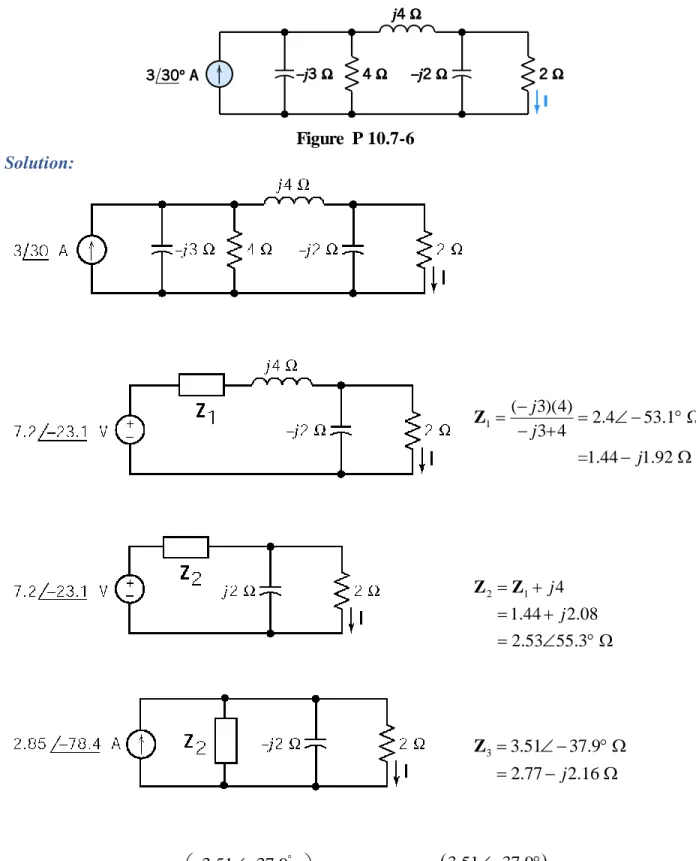
P 10.7-6 Consider the circuit of Figure P 10.7-6, where we wish to determine the current I. Use a series of source transformations to reduce the part of the circuit connected to the 2-Ω resistor to a Norton equivalent circuit, and then find the current in the 2-Ω resistor by current division.
Figure P 10.7-6 Solution:
1
( 3)(4)
2.4 53.1 3 4
=1.44 1.92
j j
j
Z
2 1 4
1.44 2.08 2.53 55.3
j j
Z Z
3 3.51 37.9 2.77 j2.16
Z
3.51 37.9
3.51 37.9
2.85 78.4 2.85 78.4 1.9 92 A
2.77 j2.16 2 5.24 24.4
P10.7-8 Determine the Thevenin equivalent of the circuit in (a):
Solution:
90 51
1
10
5 3.9 8 10
j j
j
e e
j
V
90 90
2
20
5 5.68 20 2.4
j j
j
e e
j j
V
51 90
1 2
47
3.9 5.68
3.58
j j
t
j
e e
e
V V V
8 10 2.4 20
8 10 2.4 20
t
j j j
j j j
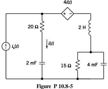
P 10.8-5 The input to the circuit shown in Figure P 10.8-5 is the current source current
is(t) = 36 cos (25t) + 48 cos (50t + 45°) mA Determine the steady-state current, i(t).
Figure P 10.8-5 Solution:
Use superposition in the time domain. Let
s1 36 cos 25 mA and s 2 48 cos 50 45 mA
i t t i t t
We will find the response to each of these inputs separately. Let ii(t) denote the response to isi(t)
for i = 1,2. The sum of the two responses will be i(t), i.e.
1
2
i t i t i t
Represent the circuit in the frequency domain as
Use KVL to get
4 i i i i
V Z I I
Apply KCL to the supernode corresponding to the dependent voltage source.
1 2
s
2 2
4 i
i i i
V Z Z
I I I
Z Z
Or, 2 s
1 2 4
i
i
Z I I
Consider the case i = 1 : is1(t) = 26cos(25t) mA. Here = 25 rad/s and
s 1
2
36 0 mA 1
20 20 20
25 0.002 1
50 15 43.3 83.9 25 0.004 i j j j j I Z Z and
150.4 35.7 mA I
so
50.4 cos 25
35.7
mAi t t
Next consider i = 2 : is2 = 48cos(50t + 45°) mA. Here = 50 rad/s and
s 2 1
2
48 45 mA 1
20 20 10
50 0.002 1
100 15 95.5 89.1 50 0.004 j j j j I Z Z
(Notice that Z1 and Z2 change when changes.)
2 52.5 55.7 mA I
so
2 52.5 cos 50 55.7 mA
i t t
Finally, using superposition in the time domain gives
50.4 cos 25
35.7
52.5 cos 50
55.7
mAP10.8-9 Determine the current i(t) for this circuit when v1(t)=10cos(10t) V
Solution:
Use superposition. First, find the response to the voltage source acting alone:
eq
10 10
5(1 ) 10 10
j
j j
Z
Replacing the parallel elements by the equivalent impedance. The write a mesh equation :
1 1 1 1
10
10 5 15 5(1 ) 0 0.707 45 A
10 10
j j
j
I I I I
Therefore:
1( ) 0.707 cos(10 45 ) A
i t t
Next, find the response to the dc current source acting alone:
Current division: 2 10
3 2 A
15
I
Using superposition:
( ) 0.707 cos(10 45 ) 2 A