Design and development of Tappered Spiral Helix Antenna for Broadband
Applications
D.Arun Kumar
Assistant Professor, ECE Department, GMRIT, RAJAM [email protected]
Abstract— The Aim of the paper is to design and develop a tapered spiral helix antenna covering the frequency range 1-18GHz. Tappered spiral helix antenna is a compact state-of-the-art circularly polarized antenna, which works over multi-octave frequency bandwidth(1-18GHz). The antenna size has been reduced by 50 percent with respect to conventional spiral antenna used for same frequency band. This antenna adequately satisfies all of the generally standardized physical constraints and limitations placed upon airborne platforms.
The spiral helix consists of a spiral antenna with a spiral radiator, the balanced to unbalanced (balun) transformer, backing cavity and a helical antenna where the outer ends of spiral antenna are terminated with a helix. The helix is placed with its axis at90⁰to the spiral lies behind it is designed to produce circularly polarized radiation over a range from 1-18GHz. In general spiral helix antenna provide frequency coverage unattainable in a single device.
The design of spiral circuit will be done using a computer generated program in MATLAB software. The design of helix is done in CST studio suite software and finally spiral and helical antennas are combined as single antenna and simulated in CST.
The simulated results are compared with aimed specifications.
Keywords— CST, BALUN, POLARIZATION, TAPPERED, ECM, ECCM.
I. INTRODUCTION
Defense systems require antennas having wide bandwidth capable of receiving signals coming from any direction with any polarization in the absence of priori information about the threat signal. The requirements become more stringent for airborne applications where weight, size and volume are at premium. The bandwidth of conventional antennas is limited because the electrical aperture dimensions change with change of operating frequency. The size of the spiral antenna is determined by lowest frequency of operation. Cavity backed spiral antennas can be used extensively for airborne systems
because of their inherent characteristics of broadband, circular polarization, compact size, lightweight and flush mounting ability.
The spiral helix antennas maintain consistent gain and input impedance over wide bandwidths with circular polarization and hence a wide range of applications exists, ranging from military surveillance, ECM ECCM to numerous commercial and private uses including consolidation of multiple low gain communication antennas on moving vehicles. For airborne platform size and weight are at premium. Many applications such as direction-finding systems or reflector feeds require a broadband antenna element that provides orthogonal senses of polarization. Polarization capability such as vertical and horizontal or right and left circular from a common aperture with coincident phase centers is of particular interest. Therefore, we are going for the design of spiral antenna which is similar in size to the spiral element, has a beam width and gain approximately the same as the spiral, but provides two orthogonal senses of polarization
II. DESIGN OFPRINTED CIRCUIT
Lowest frequency of operation = 2GHz Highest frequency of operation = 18GHz Largest round diameter = q /П=47.7mm 15% of the theoretical size = 7.15mm Actual diameter of the largest round diameter = 63mm Smallest round diameter = q /П=5.30mm
Actual size of smallest round = 5.355mm Number of turns = 24 For one arm number of turns = 4
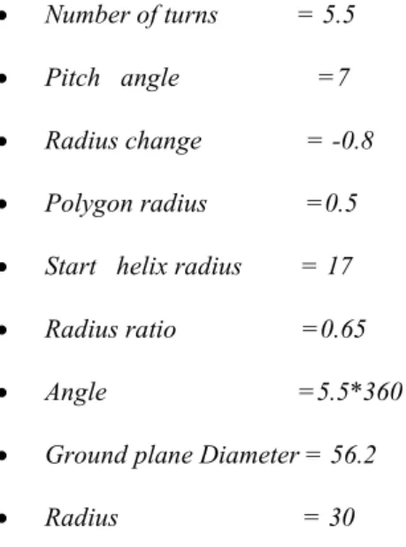
III.DESIGN OF HELIX
The optimized design parameters for helical antenna
with cylindrical ground conductor are given below.
Number of turns = 5.5
Pitch angle =7
Radius change = -0.8
Polygon radius =0.5
Start helix radius = 17
Radius ratio =0.65
Angle =5.5*360
Ground plane Diameter = 56.2
Radius = 30
A. MEASURED RESULTS
TABLE1 GAIN OFSPIRAL HELIX ANTENNA
S.No Frequency(GHz) Gain(dB)
1. 1 1.11
2. 2 4.598
3. 8 2.765
4. 18 3.899
TABLE 2 BEAMWIDTH OFSPIRAL HELIX ANTENNA
S.No Frequency(GHz) VP(Degrees)
1. 1 93.6
2. 1.2 87.3
3. 2 94
4. 4 105
5. 8 86.4
6. 18 98
TABLE 3 SQUINT OF SPIRAL HELIX ANTENNA
S.No Frequency(GHz) Squint (deg)
1. 1 1
2. 2 0
3. 4 5
4. 9.5 5
5. 14 3
6. 18 -6
TABLE 4 AXIAL RATIO OF SPIRAL HELIX ANTENNA
S.No Frequency(GHz) Axial Ratio
1. 1 2.7
2. 2 0.2
3. 4 0.8
4. 9.5 0.2
5. 14 0.1
The measured VSWR and radiation pattern with respect to frequency are illustrated in the following figures.
Fig. 1 VSWR measurement of Spiral Helix Antenna 1-18 GHz
The figure 1 represents the VSWR pattern of spiral helix antenna 1-18 GHz. From this diagram measured Maximum VSWR is -5.
Fig. 2 Radiation Pattern of Spiral Helix Antenna at 1 GHz
whereas Fig. 3 shows an example of an image The figure 2 represents the radiation pattern at 1 GHz. From this diagram measured gain is 1.11dB, beam width is 94°, and squint is 1°.
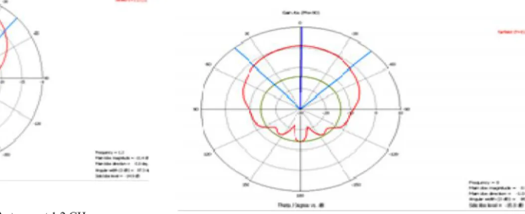
Fig.3 Radiation Pattern of Spiral Helix Antenna at 1.2 GHz
The figure 3 represents the radiation pattern at 1.2 GHz. From the diagram shown above the measured gain is -1.43 dB, beam width is 87.3° .
Fig 4 Radiation Pattern of Spiral Helix Antenna at 2 GHz
The figure 4 represents the radiation pattern at2 GHz. From the diagram shown above the measured gain is 4.598 dB, beam width is 94°, squint is 0° and axial ratio is 0.2.
Fig 5. Radiation Pattern of Spiral Helix Antenna at 4 GHz
The figure 5 represents the radiation pattern at 4 GHz. From the diagram shown above the beam width is 105°, squint is 5° and axial ratio is 0.8.
The figure 6 represents the radiation pattern at 8 GHz. From the diagram shown above the measured gain is 2.765dB, beam width is 86.4°.
Fig 7. Radiation Pattern of Spiral Helix Antenna at 18 GHz
The figure 7 represents the radiation pattern at 18GHz. From the diagram shown above the measured gain is 3.89 dB, beam width is 98°, squint is -6° and axial ratio is 0.5.
B. SIMULATED RESULTS
Fig. 8. Directivity
C. MODEL OF SIMULATED ANTENNA
Fig. 9 Model of Simulated Antenna
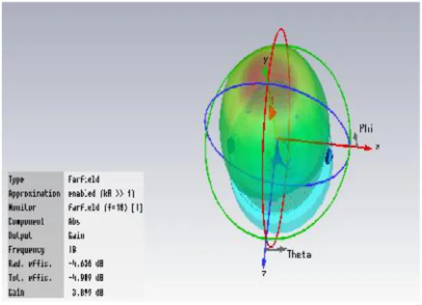
D. 3D RESULTS
These 3Dimensioanal results are represented in fig’s 10 to 14. These results are obtained at different frequencies.
Fig. 10.3d representation operating at frequency=2 GHz
Fig. 11 .3d representation operating at frequency=4 GHz
Fig. 12. 3d representation operating at frequency=8 GHz
Fig. 14. 3d representation operating at frequency=18 GHz
Fig. 11 Return Loss
IV.CONCLUSIONS
This report presents the complete theoretical analysis, and evaluation of an electrically small spiral helix antenna covering the frequency range of 1-18GHz.
The design of the cavity is very critical particularly when it is to operate over multi-octave bands. The complete design considerations of the cavity were also brought out in this report. The performance characteristics show that the antenna exhibited very good radiation characteristics over 1- 18 GHz. The measured VSWR of the Antenna is less than 3.65:1 over the entire band.
V. FUTURE SCOPE
Further scope of research is recommended in the following areas
1. In this paper a spiral helix antenna operating in 1 - 18GHz is designed.
2. Research work can be done on this type of antenna because of its advantages over conventional cavity backed spiral antennas
REFERENCES
[1] Omid Manoochehri, Seyyedpayam Abbasiniazare, and Keyvan Forooraghi, Design of a 22Tappered Dielectric-Loaded Helical Antenna Array for INMARSAT-M Satellite System, Department of Electrical and Computer Engineering, Tarbiat Modares University, MICROWAVE AND OPTICAL TECHNOLOGY LETTERS / Vol. 55, No. 11, November 2013 [2] C.A. Balanis – Antenna Theory 2ndEdition John Weily & sons,
Inc., New York 1995
[3] Nicholas Neveu, Yang-Ki Hong, Jaejin Lee, Jihoon Park, Gavin Abo, Woncheol Lee, and David Gillespie, Vehicle Applications Miniature Hexaferrite Axial-Mode Helical Antenna for Unmanned Aerial, Department of Electrical and Computer Engineering and MINT Center, The University of Alabama, Tuscaloosa, AL 35487 USA
[4] Richard C. Jhonson and Henry Jasik – Antenna Engineering Hand Book, 1993
[5] K. Fujimoto and J. R. Jonnes – Mobile Antenna Systems Hand Book.
[6] Gao, S.,Abd-Alhameed, R.A. ; Zhang, C.Design and optimisation of compact hybrid quadrifilar helical-spiral antenna in GPS applications using Genetic Algorithm, Antennas and Propagation (EUCAP), 2012 6th European Conference on 26-30 March 2012
[7] Y. T. Lo and S.W. Lee – Antenna Hand Book
[8] Brain C. Wodell – Transmission Line Design Hand Book
[9] International Journal of Advanced Research in Electrical Electronics and Instrumentation Engineering, DESIGN OF MULTI-BAND CAVITY BACKED HELICAL ANTENNA, Vol. 2, Issue 8, August 2013.
[10] R. Bawer and J. J. Wolfe – The Spiral Antenna, Aero Geo Astro Corporation, Alexandria, Virginia.
[11] Jones et al, UNITED STATES PATENT.No:5,258,770 Nov. 2, 1993.
[12] T.A. Milligan, Modern Antenna Design, John Willey & Sons Inc, 1993
[13] R.E. Collin, Foundations for Microwave Engineering,McGraw-Hill,Inc,USA,1992.
[14] R.E. Collin, Antennas and Radio wave Propagation, McGraw-Hill, Newyork, 1985
[15] Robert G. Corzine, Joseph A. Mosko – Spiral helix Antenna [16] G.S.N Raju – Antennas and Wave Propagation, Pearson Edition
2005.
[17] J. Karus - Antenna Theory, 2ndEdition McGraw hills 1998