51
CIRCULARLY POLARIZED MICROSTRIP ARRAY ANTENNA FOR
GROUND SEGMENT IN QUASI-ZENITH SATELLITE SYSTEM
Fitri Yuli Zulkifli
*)and Eko Tjipto Rahardjo
Antenna Propagation and Microwave Research Group University of Indonesia (AMRG), Center for Information and Communication Research (CICER),
Department of Electrical Engineering, Faculty of Engineering, Universitas Indonesia, Depok 16424, Indonesia
*)E-mail: [email protected]
Abstract
In satellite communication system, antenna plays an important role. Therefore, the antenna must meet some requirements, such as high gain, circular polarization, and good directivity. In this paper, a four element linear array triangular patch microstrip antenna with cross slot is designed to be used for Quasi-Zenith satellite system. A simulation study as well as experimental study was carried out. The simulation showed that the 3 dB axial ratio bandwidth of 87 MHz (2.569-2.656 GHz) is achieved while the measured results showed 96 MHz (2.556-2.652 GHz). The linear array
of 4 element antenna has a gain of 13.73 dB and maximum radiation pattern at 40° and -40°. Simulation and experiment
results show that this antenna has met the characteristic requirements of Quasi-Zenith satellite.
Abstrak
Antena Susun Mikrostrip dengan Polarisasi Melingkar untuk Segmen Bumi pada Aplikasi Sistem Satelit Quasi-Zenith. Dalam sistem komunikasi, antena memegang peranan yang sangat penting. Oleh karena itu, antena harus
memenuhi beberapa persyaratan seperti: gain yang tinggi, polarisasi melingkar dan keterarahan yang baik. Dalam
makalah ini, telah didesain sebuah antena susun microstrip secara linear yang terdiri dari empat elemen berbentuk patch
segitiga dengan slot berbentuk silang untuk sistem satelit Quasi-Zenith. Penelitian secara simulasi maupun eksperimen
telah dilakukan. Hasil simulasi menunjukkan bahwa 3 dB axial ratio bandwidth diperoleh sebesar 87 MHz (2,569-2,656
GHz) dan melalui hasil pengukuran diperoleh sebesar 96 MHz (2,556-2,652 GHz). Antena susun linear 4 elemen
menghasilkan gain sebesar 13,73 dB dan pola radiasi maksimum pada sudut 40° and -40°. Baik hasil simulasi maupun
pengukuran memperlihatkan bahwa kinerja antena telah memenuhi spesifikasi yang diperlukan untuk sistem satelit Quasi-Zenith.
Keywords:circular polarization, cross slot, microstrip antenaarray, Quasi-Zenith satellite
1.
Introduction
The Quasi-Zenith satellite system consists of three satellites orbiting at an altitude of 35,800 km above the Earth's surface as geosynchronous satellite. These satellites orbit form a figure of eight, which passes through the space above Japan to Australia and passes through the eastern part of Indonesia as shown in Figure 1. According to the plan, these satellites are used for the purpose of regional mapping position, communications, and broadcasting. These satellites operate at frequency 2.605 to 2.63 GHz [1]. When the satellites orbit crosses the eastern part of Indonesia, the elevation angle
between western part of Indonesia and the satellite is 40o-50°.
Figure 1. Quasi-Zenith Satellite Orbit [1]
To excite high gain and directivity, array techniques is one solution [2]. To achieve circular polarization, cross-slot technique is used [3-4]. This paper proposed a four element antenna array modified from [5] and [6] to increase the antenna gain.
2.
Experiment
Antenna Design. Before designing the antenna array, the single element antenna is designed first as an element of the array antenna. The single element antenna is designed using a triangular patch shape with cross slot to excite circular polarization. Triangular shape patches are chosen due to smaller size compared to rectangular patch shape [7]. The feeding technique of this antenna is direct microstrip line. This feeding technique is chosen because this technique is more easy for the fabrication process.
The design is conducted using Taconic substrate TLY 5 0620 CH-CH which has a relative dielectric permitivitty
(
ε
r) 2.2, dielectric substrate thickness (h) 1.57 mm,dielectric loss tangent (tan δ) 0.0009 and copper
conductivity 5.8 x 10⁷ S/m.
Based on [5], the length of the triangle patch antenna required to work at frequency 2.61 GHz is given by Equation 1.
r
f
c
a
ε
3
2
=
(1)simulation results using the method of moments, the
optimal length of the triangle is a = 46 mm. This means
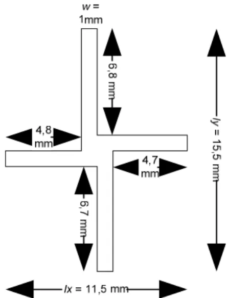
there is a reduction of 20.71% of the patch area between triangle patch and triangle patch with cross slot inserted in it.The cross slot shape used is modified from [3]. The shape and size of the slot is illustrated in Figure 2.
To determine the cross slot, the length ly must be longer
than lx in order to produce a good circular polarization
bandwidth. This slot is placed at the center of the triangle. Besides designing the cross slot, the placement of the microstrip feed line plays an important role in designing circular polarization characteristic. According to [5], the feed line position should be placed on specific loci to excite circular polarization as shown in Figure 3. The placement of the specific loci is shown as
Γ1, Γ2, Γ3 and Γ4.
Figure 2. Shape and Dimensions of the Cross Slot
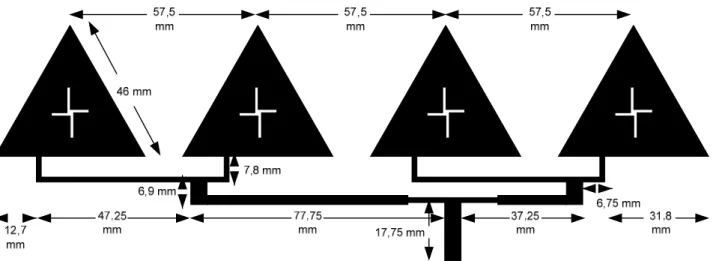
Figure 4. Final Antenna Design
To achieve impedance matching, transformation quarter
lamda (λ/4) is used, which can be calculated using
Equation 2.
1 3
T
Z
=
Z Z
(2)ZTis the impedance transformation to achieve matching
conditions on the transmission line, Z1 is the
characteristic impedance and Z3 is theimpedance load.
Equation 2 is used for power divider and transmission line to design the feed line fot the antenna array.
This single element is arrayed to four element linear
array. The distance between the elements (d) is 57.5
mm. To produce radiation patterns with maximum direction towards 40o-50o, the phase difference (β) plays an important role. In implementation, the phase difference is generated by adjusting the length of the microstrip feed line.The results of the final design of the antenna can be seen in Figure 4.
3. Results and Discussion
Simulation and measurement results of the final design of the antenna array is shown in Figure 5 to Figure 8 and is summarized in Table 1. Antenna parameters are measured in anechoic chamber in the department of electrical engineering UI. From Figure 5, it shows that
the simulated VSWR ≤ 2 impedance bandwidth of the
antenna is from 2.59 GHz to 2.63 GHz with resonant
frequency at 2.61 GHz, while the measured VSWR ≤ 2
impedance bandwidth of antenna is from 2.6 GHz to 2.63 GHz. This reflects that although there is a slight difference between simulation and measurement results, however the results still fulfill the required specification for Quasi-Zenith satellite system.
Figure 5. Impedance Bandwidth of Antenna between Measured (●), Simulated (■)
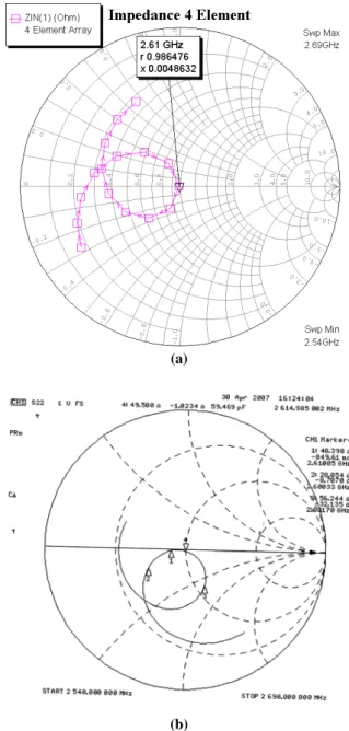
Figure 6(a) shows the simulated input impedance of the antenna at frequency 2.61 GHz is 0.9864 + j 0.00486, or about 49.3238 + j 0.2431. The measurement results of the input impedance as shown in Figure 6(b) at frequency 2.61 GHz is 49.5 + j 1.02. This value indicates that both simulated and measured input impedance of the antenna are nearly the same as the characteristic impedance of 50 ohm transmission line. Therefore matching conditions are occurred.
Furthermore, Figure 7 shows the circular polarization
bandwidth achieved from standard axial ratio ≤ 3 dB is
from 2.569 GHz to 2.656 GHz for the simulation results while the results of measurements shows from 2.556 to 2.652 GHz. This result shows that the antenna have circular polarization characteristic for Quasi-Zenith satellite applications. This meets the standards of Ministry of Public Management, Home Affairs, Posts and Telecommunications (MPHPT) Japanese for Quasi zenith satellite, which is 2.605 to 2.63 GHz.
40 35 30 25 20 15 10 5
-Magnitud
e (dB)
L 2.55
-45 - l
2.56 l 2.57
l 2.58
l 2.59
l 2.60
l 2.61
l 2.62
l 2.63
l 2.64
l 2.65
l 2.66
l 2.67
l 2.68
Frequency (GHz)
0
(a)
(b)
Figure 6. Input Impedance (a) Simulation Result, (b) Measurement Result
Figure 7. Circular Polarization Result between Measured (■), Simulated (●)
the simulation results, the radiation pattern has a
maximum beam at angle 320-330o and 30º (34º angle
precisely), the Half Power Beamwidth (HPBW) is from
21.38º to 48.56º. The measurement results show the
maximum beam occurs at 340º and 40º. The simulation tool used in this work has limitation, which is, it does not show back lobes because the tool can only show radiation pattern from -90º to 90º.
Overall, the beam form of the main lobe of this antenna shows very similar beam form between simulation and measurement results. Both main lobes of the antenna is directed towards the angle 40° and -40° (320°). This radiation pattern meets the criteria given by MPHPT,
which is the elevation angle of about 40o-50° of the
position of the satellite orbit towards the western part of Indonesia. The result which shows that the main beam direction of the antenna is towards 40° proves that the array technique used in this design can arrange the radiation pattern of the antenna as desired.
Moreover, the result depicted in Fig. 9 shows the measured antenna gain for frequencies in the antenna bandwidth characteristics. The maximum antenna gain measured is 13.86 dB at frequency 2.68 GHz. For frequency 2.61 GHz, the antenna gain is 13.73 dB. The high gain achieved by this antenna is due to the use of the array technique and the cross slot. The gain results from simulation can not be obtained because the limitation of the simulator used in this work.
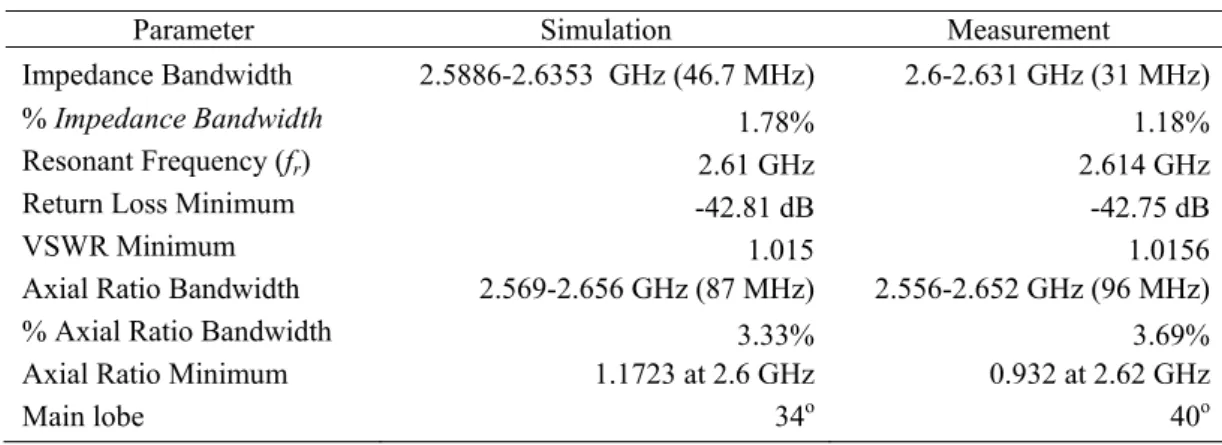
The comparisons between simulation and measurement results are shown in Table 1
Figure 8. Comparison of E-field Radiation Pattern between Simulation (■) and Measurement (◆)
Frequency (GHz)
1 - 2 - 3 - 4 - 5 - 6 - 7 - 8 -
Magnitud
e (dB)
L 2.55
0 - l
2.56 l 2.57
l 2.58
l 2.59
l 2.60
l 2.61
l 2.62
l 2.63
l 2.64
l 2.65
l 2.66
l 2.67
l 2.68
9 -
l 2.69
Table 1. Simulation and Measurement Results
Parameter Simulation Measurement
Impedance Bandwidth 2.5886-2.6353 GHz (46.7 MHz) 2.6-2.631 GHz (31 MHz)
% Impedance Bandwidth 1.78% 1.18%
Resonant Frequency (fr) 2.61 GHz 2.614 GHz
Return LossMinimum -42.81 dB -42.75 dB
VSWRMinimum 1.015 1.0156
Axial Ratio Bandwidth 2.569-2.656 GHz (87 MHz) 2.556-2.652 GHz (96 MHz)
%Axial Ratio Bandwidth 3.33% 3.69%
Axial Ratio Minimum 1.1723 at 2.6 GHz 0.932 at 2.62 GHz
Main lobe 34o 40o
Figure 9. Measured Antenna Gain
Figure 10. Antenna Gain Comparison between Single Element (●) with 4 Element Linier Array (■)
Both simulation and measurements results show similar results. The slight difference is caused by imperfection of fabrication process and the simulator used in this work. The simulator used is using method of moments (MoM) which has limitation in creating radiation pattern and exciting antenna gain.
In addition, the antenna gain measurements have been compared between single element and with four elements as shown in Fig. 10. It can be observed between single element with four elements linear array
that the single element has gain to only 6.77 dB while the 4 element linear array has increased the antenna gain to 13.73 dB.
4. Conclusion
A microstrip patch antenna array consisting of four linear triangular elements with a cross slot has been successfully simulated and fabricated. The cross slot on the patch and the position of the feed line can generate circular polarization. Moreover, the cross slot can reduce the size of the patch area upto 20.71%. The measured impedance bandwidth is 31 MHz, (2.6 to 2.631 GHz). The measured circular polarization bandwidth is 96 MHz (2.556 to 2.652 GHz). The antenna gain is 13.73 dB at the working frequency. All antenna parameters measured is in compliance with the requirements of the Quasi-Zenith Satellite.
Acknowledgement
The authors would like to thank Mr. Leon Dhy Deardo for his technical assistance in this research.
References
[1] MPHPT Communication News, Frequency
Allocations for Sound Broadcasting Satellite via
Quasi-Zenith Satellites, www.soumu.go.jp/joho_
tsusin/eng/Releases/NewsLetter/Vol14/Vol14_08/Vo l14_08.html, 2003.
[2] C.A. Balanis, Antena Theory: Analysis and Design,
3rd ed., John Willey and Sons, New York, 2005,
p.1136.
[3] R. Anggorodi, E.T. Rahardjo, F.Y. Zulkifli, Proceedings of Quality in Research, Department of Electrical Engineering University of Indonesia, Jakarta, Indonesia, 2005.
[4] J.H. Lu, C.L. Tang, K.L. Wong, IEEE Trans. Antennas Propagat. 47/7 (1999) 1174.
13.55
[6] F.Y. Zulkifli, ET. Rahardjo, D. Hartanto, Progress In Electromagnetic Research M (PIER M) 5 (2008) 101. doi: 10.2528/PIERM08101601.