22
InnovativeResearch in Engineering Sciences Vol 2(4), 22-34 (2016)
Journal of Innovative Research in Engineering Sciences
ISSN(2476-7611) Article InfoReceived: 15 October 2016 Accepted: 20 December 2016
Journal homepage :
www.Joires.com
Error recognition and error elimination in dc-dc three-level convert with capacitors voltage
control method
Hamid Tayefe Ghahremani 1*, Babak Abdi 2, Yasin Fathi Zadeh3
1MSC student power engineer, Islamic Azad University, Tehran, Iran. 2P.H.D power engineer, Amirkabir university of Technology, Tehran, Iran.
3MSC power engineer, Islamic Azad University, Tehran, Iran.
Abstract: The DC-DC converters are widely used in audio systems, alternative energy sources, backup power supplies, rechargeable batteries, telecommunication equipment, computers; hybrid electric vehicles, laptops, televisions and many other components used in commercial and industrial, one of these converters are multilevel converters. Multilevel converters in power systems play an important role in the power delivery. This type of transducer has inherent advantages including the ability to function under high voltage and power, improving the quality of the output waveform and flexibility which cusses to attracts most of the industry. Therefore the aim of this study was to detect the error and fix it in three-level converter using capacitor control method. This study is intended to identify and eliminate possible errors exists in the power system by floating capacitor. The advantages of this method are low cost compared to other methods and high speed performance which can be highly efficient when faced with short-circuit fault.
Kay words: Transformers DC-DC, Floating capacitance, Power system, Identify the Fault.
1. Introduction
DC-DC converters are electronic devices that change voltage level from one level to another for better efficiency of electronic power. The high voltage DC-DC converters are widely used in a variety of accelerators, modulators, X-rays generators etc.[1-3].Also there is huge increase in energy demand in recent decades which accelerated the consumption of fossil fuels. International Environmental organizations and police make new decision to expand the small-scale power generation network. The DC-DC converters with their high efficiency widely used in industries such as solar cells, fuel cells and hybrid vehicles, etc.... These converters convert low DC voltages to higher voltage with low ripple [4]. DC / DC converters can be divided up into high-power and low-power DC / DC converters [5]. High power converters have wide applications in industry. They can be used in petrochemical, cement plants, pumps in water injection stations, transportation in transport industry, steel rolling machines in metal industry, network integration of renewable energy sources, reactive power compensation and other applications and many other applications. Development of high power converters and mean voltage drives began in the mid-80s that Gate Turn-off Thyristors (GTOs) were commercially available. GTO was the standard key for mean voltage drives until the late 90s that single-gate bipolar transistor (IGBT) and Turn-off Thyristors by changing the gate (GCT) were invented. These switching equipment’s are widely used in high power drives due to the excellent switching characteristics, less power losses and ease of controlling their gates. For the purpose of this research based on three-level DC-DC
converters, the introduction of multilevel converters discussed here.
Multilevel converters are power electronic
converters which desirable output voltage prepared through switching of numbers of input DC sources. One of the advantages of multilevel converters is improving the quality of the output waveform. The output voltage quality depends on the number of converter voltage levels. The more number of voltage levels in the structure of this converters, the higher output voltage quality [6].
In medium-voltage and high power, multi-level structure of a power converter is an alternative and good working condition of this range of voltage and power achieved [7].
Industrial multilevel converters are divided into three main classes. The three categories include diode clamped inverter, inverter with floating capacitors and H bridge inverter [8]. Another benefit of multilevel inverters includes output voltages with extremely low distortion, reduce stress caused by dv / dt, reducing stress on semiconductor switches and reducing the common mode voltage.
Given that each method has its advantages and disadvantages, choosing the right method depends on the specific application, performance requirements and desirable standards. Specifications include: high power density, small size, low cost, high efficiency and reliability, fast transient response, low noise and low harmonic distortion. In other words, in high-power systems, power losses in power inverters during the switching are to extent that limit switching frequency [9].
23
Also the multilevel inverters based on dc voltage sources divided into two categories: symmetric and asymmetric. In symmetric structures the size of dc voltage sources are different. Asymmetric structures in contrast with symmetrical structures have number of output voltage levels and more complex design. Ac output production from dc voltage sources can be problematic. In other words, increase of output voltage levels lead to increase in semiconductor devices required. Symmetric structures Has the advantage of modular design which makes comfortable development in these structures. In addition to these conventional multilevel inverters a new generation of inverters has been presented with a special structure in the current year. This subsystem is based on symmetric structures that were connected in series to each other. In an asymmetric structure, a dc source is different with other in subsystems. Dc voltage sources are dependent on the number of dc source structures in each sub-system. Although the number of output voltage levels in this type of structure, but application of specific amounts of dc sources lead to complexity and difficulty to achieve [10-12]. In the asymmetric structures, asymmetric voltage sources compared to symmetric structures has much more output voltage levels, which makes the system requires a complex design for construction of multilevel converters, so production of output voltage with different values could be Problematic. In other words, increase in the output voltage leads to increase number of semiconductor devices required. Symmetric structures have modular design advantage that makes the development of these structures easy [13].On the other hand reliability has been an important concern in power converters. Probability of error even exists in well-designed circuits. Error detection and protection are two important aspects of power converters design, especially in high voltage and power applications. In high voltage and power systems, the failure is high cost and consecutive failure is very important [14].
In voltage conversion applications, the three-level DC-DC converters and other its derivatives are the choice of most engineers in the design of electronic systems. The most important benefits of these converters are the main switching up to about half line voltage which causes to better performance of output devices. On the other hand these converters needs balance voltage levels at the input and two diodes to ensure the proper functioning of the system at the output. Expensive tools and equipment in high voltage and power systems, Makes the protection of these systems very important. One of these devices is three-level DC-DC converters. Inability to recognize the error and fix it
increased costs of operation [15].
According to the description provided, this study intended to identify and eliminate possible errors exists in the power system by floating capacitor. This method has low cost compared to other methods and also has high speed performance which can be highly efficient when faced with short-circuit fault. The method presented here is a way that not only resists from shutting down the system caused by unwanted voltages in switching, but has the solution to compensate the error created to protect the remaining components in the system. The solution to any abnormal situation has been introduced. In addition the presented converter can be protected against multiple errors through capacitor voltage control method. Protection circuit can be easily designed and implemented.
2. Research Methodology
In this study by the implementation of power system with three-level DC-DC converters in MATLAB and controlling voltage of floating capacitor with Pulse width modulation method and create real conditions to evaluate proper error detection and error handling method as quickly as possible. Finally curves and target parameters for different values of input parameters and simulation results obtained and analyzed by modeling and simulation in Matlab software [16-18].
The introduce system will be a system with zero switching voltage for high input voltage and average power applications. This three-level system includes pulse width modulation circuits in the same power of three-level phase shift method by voltage switch MOSFET (half the input voltage) have been balanced and implemented. So stress and power of transformator
and semiconductor devices in secondary
reduced.[19]The resonator Inductor and capacitor are like active switches which work in wide range of voltage and load conditions. The way in which one of the external switches must be turned off before the internal switch to avoid abnormal conditions for the system. Matching With each three level circuit, each Transformer can be as a predecessor to output the current or does duty of power transformer, so the transformer does not need a secondary side, three medium tap in parallel with secondary to reach a common load. [20-22].
An example of this DC / DC converter system will be reviewed.
24
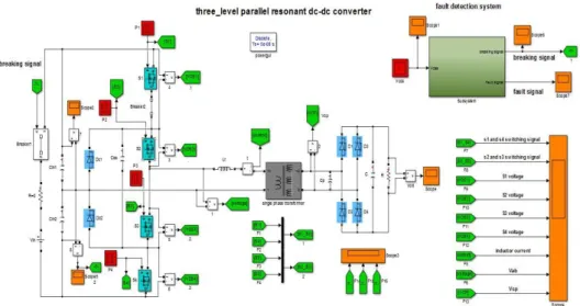
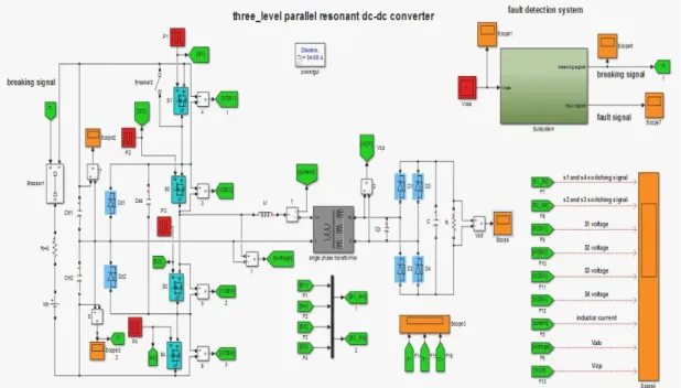
Figure 1. Configuration of three-level parallel resonator DC / DC converter.
The main advantage of converter DC / DC is that the main circuit switch use half the dc-link input voltage so the lower voltage level used, better performance in the system achieved. Three level converters should be in balanced with vin1 dc and vin2 dc and also diode voltage and make sure to achieve common voltage.
Movable capacitor Separates External switches (s4, s1) from internal switches. When one of the external switches off the parallel capacitor is being charged and capacitor in parallel with an external switch is in discharge mode. Movable capacitor is like a zero voltage switch.
In deed the Movable capacitor in parallel with the
input capacitors will be free during a period of time so can reduces imbalance by input pulse width modulation. Also The Movable capacitor can be used as an aid to internal switches; under these conditions Vcc voltage must be equal to Vin/2. This voltage indicates that the circuit is in abnormal condition and has dissociation and a way to detect errors. When there is no protection circuit in the system it will cause problems. If an external switch short-circuits without protection circuit, one of the internal switches with an external switch stops. If the neutral point voltage is normal, due to the lack of protection circuit other switches fail.
Figure 2. Protection method proposed based on Vcc detection.
Advantages of this method are as follows:
1) No additional sensor components or steps, will not be turned on so has no impact on normal performance
2) Sensitivity to unbalanced voltage switches and domains fault detection
3) Quick response during short circuit error 4) Low cost and easy implementation 3- System fault analysis in simulation
MATLAB Simulink was used for simulation. In Figure 3 the schematic of the system and used blocks displayed. Any of the cases where the fault occurs will be explained.
Open lope Switch
25
Figure 3. Open loop in S1.
Floating capacitor placed in loop to recognize the system errors by measuring the voltage across it. In the circuit input capacitor voltage is half of the input voltage and due to the transformer there is high output voltage.
The output of the capacitors in Figure 4 and 5: When s1 switch is open, we expect that capacitor is isolated due to short-circuit ring.
Figure 4. Cin1 Voltage.
According to the previously explanations When the s1 circuit switch is open, there is short circuit ring by
26
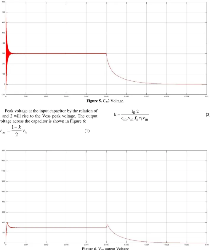
Figure 5. Cin2 Voltage.
Peak voltage at the input capacitor by the relation of 1 and 2 will rise to the Vcss peak voltage. The output voltage across the capacitor is shown in Figure 6:
in
css
v
k
v
2
1
(1)0
in in s in I .2 k
c .v .f . .v
(2)
27
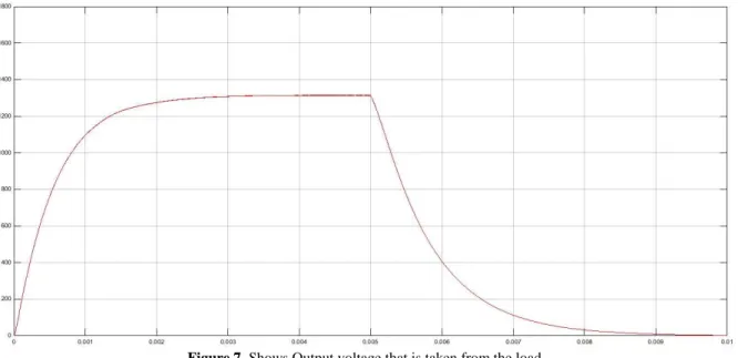
Figure 7. Shows Output voltage that is taken from the load
Due to the discharge of lower input capacitance and peak voltage for voltage of the Movable capacitor, output voltage drop and goes to zero.
With regard to protection circuits that exist in the
system, the presence of such subsystem shown below in Figure 8 can identify abnormal conditions of the system and stop the circuit.
Figure 8. Fault detection subsystem
Interior view of Figure 8 is shown in Figure 9 .
Figure 9. Internal schematic of subsystem
28
and floating capacitor.Figure 10. Compares the voltage at the open connection.
Short-circuit of the switch
When the s1 switch is shorted, float capacitor
voltage increases and equals with the input voltage. Figure 11 shows the short circuit of the system.
29
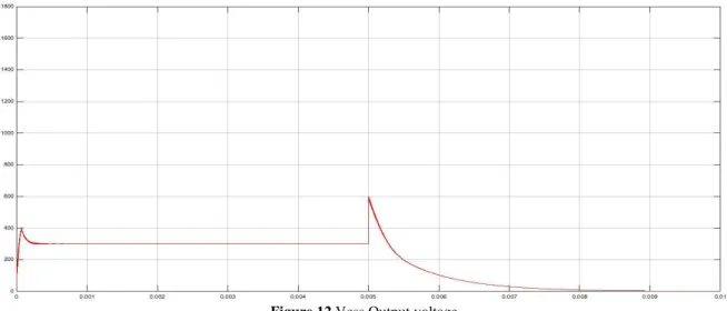
Figure 12.Vcss Output voltage
In this case s3 and s4 are on and existing fault has no effect on the neutral point and input voltage balance.
Figure 13 shows the results. Above input capacitor voltage
Figure 13. Lower input capacitor voltage
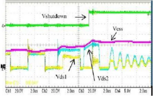
When abnormal conditions occur in systems and floating capacitor voltage getting equal to the input
voltage, the protection circuit stops the System. Figure 14shows s1, s2 and floating capacitor voltage.
30
S2 Open SwitchInternal open circuit is like short circuit of external switch and the voltage of floating capacitor increases up
to the input voltage. Figure 15 shows the Schematic of the system.
Figure 15. S2 switch open circuit
Two systems of internal switch Open circuit and external switch short circuit not observe ZVS condition and s1 switch dose not turn off before the s2 switch. But
this abnormal condition has no effect on the input capacitor voltage and balance of neutral point. Figure 16 shows the output voltages.
Figure 16. Compares the voltages at open circuit
S2 switch short-circuiting
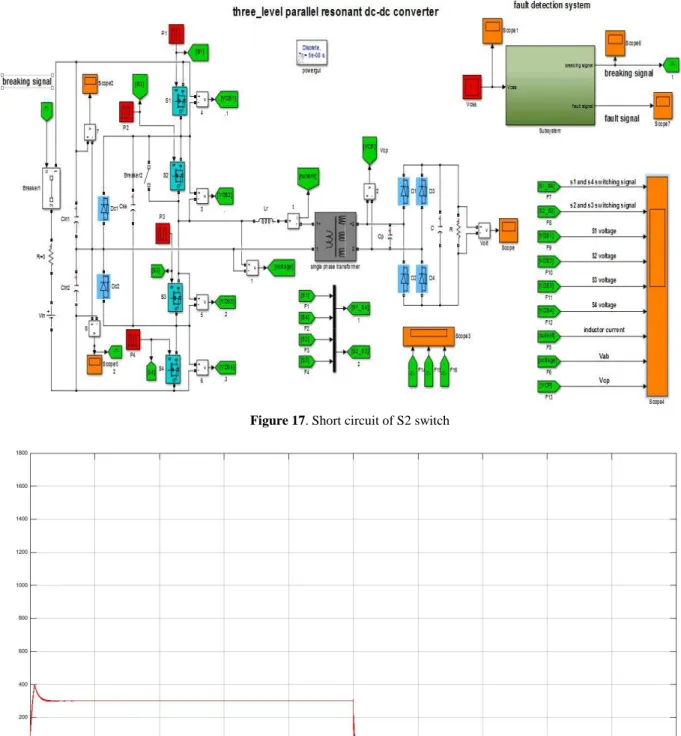
If S2 switch were short circuit, S1 switch is open and circuit Performance depends on the status of S3 and S4. Figure 17 shows an Overview of short circuit.
31
Figure 17. Short circuit of S2 switch
Figure 18. Vcss Voltage
32
Figure 19. Input up and down capacitor voltage
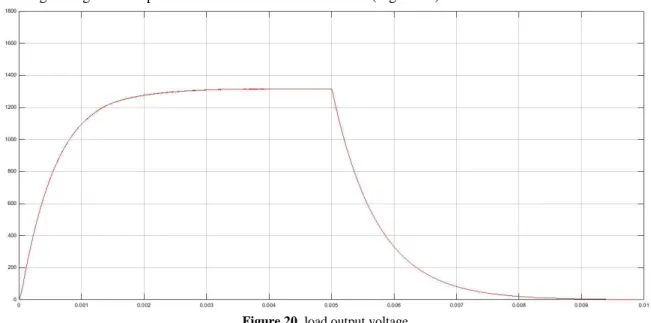
Output voltage is high and drops when there are normal conditions. (Figure 20)
Figure 20. load output voltage
If the S3 and S4 switches are turned on, the moving capacitors will short-circuits. Figure 21 shows output
voltage in S2 short circuit condition.
33
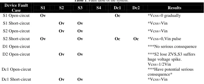
Due to the varying of S3 and S4 switches status, Vcss voltage will be damped sinusoidal waveform like.In Table (1) all Different abnormal conditions in three-level system is shown.
Table 1. Fault table of the system.
Device Fault
Case S1 S2 S3 S4 Dc1 Dc2 Results
S1 Open-circut Ov Oc *Vcss=0 gradually
S1 Short-circut Ov Ov *Vcss=Vin
S2 Open-circut Ov Ov *Vcss=Vin
S2 Short-circut Ov Ov Oc Oc *Vcss=0,Vin pulse
D1 Open-circut ***No serious consequence
D2 Open-circut Ov Ov ***S2 lose ZVS,S3 suffers
huge voltage spike. Vcss=1/2Vin
Dc1 Open-circut ***Have potential serious
consequence*
Dc1 Short-circut Ov Ov *Vcss=Vin
Also the system parameters used in this thesis are given in table (2).
Tabale 2. Converters Key parameters
Parameters Value
Transform turn ratio (secondary over primary) 11
Voltage Gain (M) 3
Capacitor (Cp) 1.24 nµ
Inductor (Ls) 3.6 µH
Flying capacitor (Css) 2µF
3. Suggestions
In this thesis, in order to resolve the error by three-level DC-DC converters, Capacitor voltage control method was used. According to material presented in this discussion, attempts to use other methods to correct errors in the system in future research and by compare the performance of these methods come to a conclusion for the better method based on better performance to fix errors in multi-level DC-DC converters.
Conclusions
There are different types of DC-DC converters. In this article we observe three-level DC-DC converters and by detection of errors in this type of converters tries to fix the three-level DC-DC converters errors by capacitor voltage control. In Simulation and the results it was found that the capacitor voltage control method and use of floating capacitance, well resolved voltage unbalance errors.
References
1) Delshad, M. and Fani, B. (2009), Designing and
producing a DC-DC converter of a new current supply with soft switching, (ZCS) electronic and
power magazine, electronic engineer college, first year, issue 2.
2) Delshad, M. (2008), DC-DC converter of a new
current supply with soft switching for average power applications, Majjjlllesi scientific search journal of electrical engineer, year 2, issue 2.
3) Ezatpanah Latifi, M., Babaee, E., Rezaeepour, R.
(2014), Representing a new structure for symmetric multi-level inverters, 28th international conference of electronics.
4) Ghoreishi, H. A. Yazdian, A., Rajaee,
Mohamadian, M. and Farhangi, Sh. (2014), designing and implementing multi-level converter to realize simultaneous modulation of amplitude and pulse width in electrical driving applications, doctoral thesis in power electronics, Tarbiat Moddares university, faculty of technical engineer
5) Das, P., Pahlevaninezhad, M., and Singh, A.
(2015), A Novel Load Adaptive ZVS Auxiliary Circuit for PWM Three-Level DC-DC Converters.
6) Da Silva, E. R. C., Lima, A. M. N., de Oliveira Jr,
A. S., Jacobina, C. B., and Razik, H. (2006), Detection and compensation of switch fauts in a three-level inverter. In PESC 2006.
7) Jovcic, D., and Zhang, J. (2012), High power
IGBT-based DC/DC converter with DC fault tolerance. Proc. IEEE PEMC.
8) Ivensky, G., Gulko, M., and Ben-Yaarov, S.
34
converter. Aerospace and Electronic Systems, IEEE Transactions on, 33(1), 53-63.9) Merlin, M. M. C., Green, T. C., Mitcheson, P. D.,
Trainer, D. R., Critchley, D. R., & Crookes, R. W. (2010, October), A new hybrid multi-level voltage-source converter with DC fault blocking capability. In AC and DC Power Transmission, 2010. ACDC. 9th IET International Conference on (pp. 1-5). IET.
10) Ribeiro, E., Cardoso, A. M., and Boccaletti, C.
(2013), Fault-tolerant strategy for a photovoltaic DC--DC converter. Power Electronics, IEEE Transactions on,28(6), 3008-3018.
11) Son, H. I., Kim, T. J., Kang, D. W., and Hyun, D.
S. (2004, June), Fault diagnosis and neutral point voltage control when the 3-level inverter faults
occur. In Power Electronics Specialists
Conference, 2004. PESC 04. 2004 IEEE 35th Annual (Vol. 6, pp. 4558-4563). IEEE.
12) Son, Ho-In, Tae-Jin Kim, Dae-Wook Kang, and
Dong-Seok Hyun. Fault diagnosis and neutral point voltage control when the 3-level inverter faults occur, In Power Electronics Specialists Conference, 2004. PESC 04. 2004 IEEE 35th Annual, vol. 6, pp. 4558-4563. IEEE.
13) Merlin, M. M. C., Green, T. C., Mitcheson, P. D.,
Trainer, D. R., Critchley, D. R., and Crookes, R. W. (2010, October), A new hybrid multi-level voltage-source converter with DC fault blocking
capability, InAC and DC Power Transmission,
2010. ACDC. 9th IET International Conference
on(pp. 1-5). IET.
14) Jovcic, D., and Zhang, J. (2012), High power
IGBT-based DC/DC converter with DC fault
tolerance.Proc. IEEE PEMC.
15) Ribeiro, E., Cardoso, A. M., and Boccaletti, C.
(2013), Fault-tolerant strategy for a photovoltaic
DC--DC converter.Power Electronics, IEEE
Transactions on,28(6), 3008-3018.
16) Jin, K., and Ruan, X. (2006), Hybrid Full-Bridge
Three-Level LLC Resonant Converter&# 8212; A Novel DC&# 8211; DC Converter Suitable for Fuel-Cell Power System. IEEE Transactions on Industrial Electronics, 53(5), 1492-1503.
17) Franquelo, L. G., Rodriguez, J., Leon, J. I., Kouro,
S., Portillo, R., and Prats, M. A. (2008), The age of multilevel converters arrives, IEEE industrial electronics magazine, 2(2), 28-39.
18) Canales-Abarca, F., Barbosa, P. M., and Lee, F. C.
(2002), U.S. Patent No. 6,349,044. Washington, DC: U.S. Patent and Trademark Office.
19) Bhat, A. H., and Agarwal, P. (2008), Three-phase,
power quality improvement ac/dc
converters. Electric Power Systems
Research, 78(2), 276-289.
20) Shi, Y., and Yang, X. (2013), Zero-voltage
switching PWM three-level full-bridge DC–DC converter with wide ZVS load range. IEEE Transactions on Power Electronics, 28(10), 4511-4524.
21) Khomfoi, S., and Tolbert, L. M. (2007), Multilevel
power converters. Power electronics handbook, 451-482.
22) Shukla, A., Ghosh, A., and Joshi, A. (2010),