Download complete issue: Vol. 2, No. 1 (PDF)
8
0
0
Full text
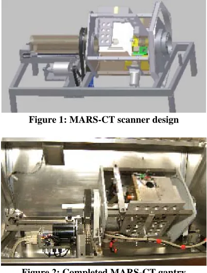
(2) 4. INTERNETWORKING INDONESIA JOURNAL. characteristics such as sensor material and low energy chargesharing effects. The scanner was built to prove both the detector’s abilities and the scanner design; it had to be safe, robust, architecturally flexible, transportable and affordable. Figures 1, 2, 6, 7 and 8 show a MARS-CT scanner design, a photograph of the completed MARS-CT gantry, the object and detector translation axes, MARS-CT scanner and a top view of the loaded specimen, respectively.. ZAINON ET AL.. produce spatial registration errors between each the two energies. Most CT advances have been to improve the use of absorption information and to reject scattering information. Of all the areas of possible improvement for radiation detectors, energy discrimination of incident x-ray photons is the most promising [4]. Energy discriminating photon counting pixel detectors, such as Medipix, enable recording of energy spectrum of the x-ray beam. MARS-CT uses a single standard x-ray beam with a spectral detector. Thus, multiple energy measurements can be obtained. The Medipix detector is a photon counting detector. That is, it records the properties of an x-ray beam on a photon by photon basis with virtually no detector noise. In particular, each pixel of the Medipix detector has the electronics to measure and record the energy of each photon. The extra energy information provides enhanced differentiation between tissue types such as bone, muscle, fat and contrast agents without the drawbacks of the dual source approach.. Figure 1: MARS-CT scanner design. Figure 2: Completed MARS-CT gantry In Figure 3, different types of CT imaging techniques are given. These ranges from standard (broad spectrum) CT to dual-energy CT and spectral CT (MARS-CT) [3]. In standard CT, machines are only capable of measuring the overall attenuation of x-rays as they pass through an object. Each material’s x-ray attenuation depends on its atomic number and electron density. A CT image is created by directing x-rays through an object from multiple orientations and measuring their resultant decrease in intensity. The grey levels in a CT slice correspond to x-ray attenuation, which reflects the proportion of x-rays scattered or absorbed as they pass through each voxel. Standard single energy CT characterises tissues with a single scalar value (Hounsfields Unit) giving total attenuation.in a voxel. Dual-energy CT systems have been developed as a technique for improving material separation capabilities by using x-rays from a single source repeated at a different tube kilovoltage, or by using dual sources (x-ray tubes at 90 ˚). While dual-energy CT obtains additional information about the elementary chemical composition of the scanned material, images are limited to two energies with overlapping x-ray spectra. In addition, rotation of the gantry or x-ray tube offset. Figure 3. Different types of CT imaging techniques A. Medipix2 Detector and the Detection Principle of x-rays Advances in CMOS technology have opened up new possibilities in particle detection and imaging. In recent years, particle physics experiments have been transformed by the introduction of application-specific integrated circuits (ASIC) particularly for tracking detectors. Pixel detectors have become key components in tracking systems, especially in high radiation environments where excellent spatial resolution is combined with extremely high signal to noise ratios. This allows physicists to find evidence of rare particle tracks in very complicated events [5]. The Medipix2 chip demonstrated that the photon counting approach provides images with excellent dynamic range which are practically free of nonphotonic noise [6]-[7]. Figure 4 shows a schematic diagram of the Medipix2 detector.. ISSN: 1942-9703 / © 2010 IIJ.
(3) Vol.2/No.1 (2010). INTERNETWORKING INDONESIA JOURNAL. 5. Figure 5: Medipix2 detector Figure 4: Schematic diagram of Medipix2 The Medipix2 chip (Figure 5) consists of 256 x 256 identical elements. Each works in single photon counting mode for positive or negative input charge signals. An incident x-ray photon generates a cloud of electron-hole pairs in the semiconductor (eg. silicon or CdTe) sensor layer of the detector. These charge pairs are measured by the underlying ASIC layer. The electronics of each pixel counts the photons incident on the sensor, but can also be set to only count photons that fall within a certain energy range. Each Medipix2 pixel is 55 µm2, giving a spatial resolution comparable to mammographic film; the film with the smallest grain size in regular use in medical imaging. Each Medipix2 pixel acts as an individual spectral detector. The logic circuits for each pixel (approximately 600 transistors) can analyse incoming events at near megahertz rates, comparing the charge of the electron-hole cloud with preset threshold levels. That is, an incident photon is only counted if its energy is above this software selectable threshold. The results are to have an imaging detector with a spatial resolution of 55 µm2 and an energy resolution of about 2 keV across the range of 8 – 140 keV. In summary, the Medipix2 detector is a hybrid ionising particle detector designed to provide energy selective images at high spatial and temporal resolutions. These position sensitive detectors have been successfully used in spectroscopic radiation measurements [6]. In Medipix3, the latest version of the chip, each pixel has two thresholds and two counters allowing for two simultaneous energy measurements with. In addition it has another mode in which group of four pixels communicates to produce a super-pixel capable of simultaneously reading eight energy windows simultaneously. These allowing for true spectroscopic CT without multiple x-ray exposures. Medipix3 also has significantly improved energy resolution because each pixel communicates with its neighbor to correct for charge sharing effects.. B. MUROS Readout System The Medipix2 re-Usable Readout System, version 2, (Muros2) board is an interface between a board carrying a maximum of four Medipix2 chips and a National Instruments DIO-653X board. The Muros2 has been developed at the National Institute for Nuclear Physics and High Energy Physics (NIKHEF) as a successor to the Muros1 board, (designed for Medipix1) [7]. The Muros2 board supports serial communication with the Medipix2 chip. C. Gantry and Housing The scanner is built around a stable steel frame made of 50 x 25 mm2 welded box-section steel. This is designed to keep any twisting or vibration to a minimum. The scanner gantry is constructed from two solid steel endplates attached to each other by four steel rods to form a strong and rigid rotating unit. The endplates rotate on large diameter bearings, leaving a 106 mm hole for sample tubes to pass through. This gives a maximum sample size of 100 mm. One side of the gantry is formed by a solid steel base plate, which provides support for the x-ray tube and the detector. All sides are covered by stainless steel panels, one of which has a primary 3 mm lead barrier for radiation shielding. The scanner is housed in a lead shielded box (Figure 5) which consists of 1.8 mm lead sandwiched between 0.5 mm aluminium and 0.5 mm stainless steel. The box has interlocked access on sample doors, and shielded ports for cable entry and ventilation. A warning light on the scanner box is illuminated when x-rays are being produced. There is no measurable radiation outside the box. Cables going to the rotating gantry are arranged to accommodate a half twist as they leave the scanner through a port in line with the centre of rotation. The micro focus tube and high voltage generator are fixed to a base plate on one side of the gantry. This base plate can be moved in or out to give the most efficient position ensuring complete coverage of the sample object. A fan has been mounted to cool the x-ray tube and allow continuous operation at full current. On the opposing side, a Medipix2 detector is positioned. It is mounted on a plate that allows fine angular adjustment to ensure the detector pixels are aligned with the vertical axis. Since the detectors are small (either a. ISSN: 1942-9703 / © 2010 IIJ.
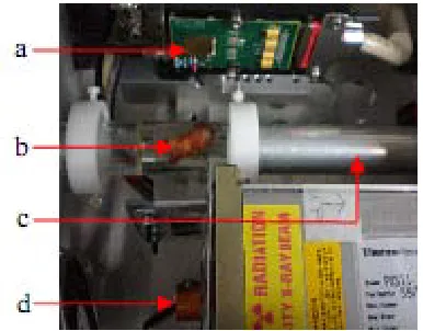
(4) 6. INTERNETWORKING INDONESIA JOURNAL. ZAINON ET AL.. single detector chip at 14 x 14 mm2 or a quad detector assembly at 28 x 28 mm2) they may need to be translated vertically to create a complete projection radiograph. The mounting plate is connected to a screw drive which accurately translates the detector to each imaging position. The screw drive is supported by the steel base plate and can be translated perpendicular to the access of rotation to accommodate different sample sizes, which range from 25 to 80 mm.. Figure 8: The MARS-CT gantry with its main components labelled (a) Medipix2 detector, (b) sample (in this case a human atheroma plaque fixed in Perspex), (c) sample holder and (d) micro focus x-ray tube. Figure 6: The scanner axes. D. X-ray tube A Thermo Scientific Kevex PXS11-150-75 is the x-ray source for the MARS-CT scanner. It is a portable x-ray source with 75 kV and 11.25 W. It has constant potential and minifocus for use in high resolution radiography and real time imaging applications. The 40 μm spot size delivers high resolution direct x-ray magnified images over the entire range of operation. In spite of its high performance, the Kevex PXS11 uses a filament cathode, thereby eliminating the need for bias or focus supplies which are necessary for dispenser cathode type x-ray tubes. The Kevex PXS11 combines the x-ray tube, high voltage power supply and control circuitry in one compact package that is powered from a 28 VDC source. The specifications of this micro focus x-ray tube include: a 8.9 mm Focus-to-Object Distance ( FOD) which enables high magnification; a high flux output of 70 R/min at 11.25 W; an operating voltage range of 40–75 kV ± 1%, which enables use with a wide range of materials; an integrated source-tube power supply and control circuitry; an internal cooling fan. The x-ray tube weight is approximately 4 kg.. Figure 7: MARS-CT scanner with its main components labelled (a) lead shielded box, (b) stepper motor, (c) gantry, (d) motor controller, (e) x-ray controller, (f) fan switch, (g) power supply and (h) MUROS power.. E. Operation of the MARS-CT scanner usingMedipix2 The operation of the x-ray tube, the stepper motors and the Medipix2 detector is controlled by Matlab on a dedicated PC. Serial interfaces are used for the x-ray tube and stepper motors. The Medipix2 detector is read using Pixelman software [8] via a custom designed Pixelman-Matlab interface. The user defines a number of parameters before scanning. These include the number of rotational steps, the number of sensor positions (to enlarge the field of view), the threshold settings and corresponding acquisition times. In order to simplify cable management on the gantry, the scanner is designed to complete one revolution and then return to the starting position. The detector and x-ray source are mounted on the gantry with the sample between. An image (called a frame) is taken and then gantry rotated. Then the detector and source are rotated around the sample. At the next stop another next. ISSN: 1942-9703 / © 2010 IIJ.
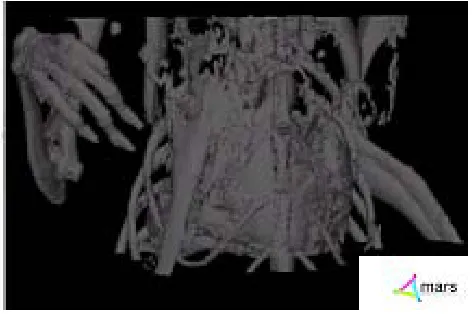
(5) Vol.2/No.1 (2010). INTERNETWORKING INDONESIA JOURNAL. projection frame is taken. This process is repeated around the entire sample. The number of stops and therefore projection frames taken is determined by the user. For larger samples the detector can be moved linearly up and/or down and the process repeated. This creates more than one frame at each rotation stop. The frames are stitched together to form the projection images. A small overlap of a few pixels maintained in the movement to help check alignment and to ensure consistent exposures. All scanner control and image triggering is performed via Matlab routines. Table 1 shows an example of typical scan parameters for four energy bins. The reduced time at lower energies is to ensure that a similar number of photons are measured above each threshold. Table 1: Scan parameters for mouse with four energy bins Energy (keV) of the low threshold 12 17 33 42 Time (s) 0.3 0.3 1.5 3.0. III. IMAGE RECOVERY, PROCESSING AND VISUALISATION Images obtained from the multi-energy MARS-CT scanner were processed by back projection to a 3D volume data set using Octopus version 8.2 [9]. Octopus is commercial tomography reconstruction software for cone beam CT, spiral CT, or parallel beam CT. The software allows the user to change a number of settings concerning the pre-processing and filtering. Pre-processing steps are included in the package such as ring filtering, normalisation, beam hardening correction and axis tilt correction. In addition, the CBCT reconstruction algorithm was also implemented in Matlab to reconstruct images from the projections. A variation of the Feldkamp, Davis and Kress cone-beam computed tomography (CBCT) algorithm (TFDK-algorithm) [10] was used to reconstruct the images. This includes two steps of rebinning the projection data and performing a filtered backprojection. Additional preprocessing of the raw projection data was required due to the special scanner geometry. The point source emits a cone shaped beam, which is detected by the two-dimensional Medipix detector. The detector rotates simultaneously around the centre of rotation, which ideally is in the centre of the object. Each pixel of the projections obtained with a cone-beam can be characterized by the rotation angle α, the fan angle γ and the cone angle θ. In the first step of rebinning, the so called row-wise rebinning, one row of the pixels is taken which implies a fixed value of the cone angle θ. The lot of the same rows from all projections represents a fan-beam set-up and can be converted into parallel-beam geometry. Each set of rotation angle and fan angle can be described by a corresponding pair of rotation angle and distance u of the x-ray detected by this specific pixel to the centre of rotation. Now using one column of this row-wise rebinned data at a time (fixed value of u), the second step of rebinning is done which involves projecting the row-wise rebinned data onto a planar and rectangular virtual detector. After applying a weighting factor to each pixel accounting for the angle of the. 7. x-ray detected by this specific pixel to the horizontal plane, the object can be reconstructed with filtered backprojection. The 3D reconstructed images can be used for visualisation purposes to produce a more comprehensive model of the object. A research program for volumetric visualisation, called MARSExplorer, is being developed for the interactive exploration of the spectroscopic data as volumetric objects. This will allow for better diagnosis and interpretation of medical and biological data. MARSExplorer provides multiple views to allow for comparison of energy bins side by side or multiple views of the same energy bin. Each view can combine energy bins with simple techniques including finding the average, difference, and maximum and minimum voxels between two energy bins. Also, three energy bins can be assigned to the three primary colours to directly compare brightness levels of the voxels and contrast the differences with the resulting colour (colour combination mode ) . MARSExplorer provides a basic set of volumetric tools for navigating through the energy bins. These tools include slicing the volume, controlling the transparency and thresholding the luminance range. The tools are mapped to slider bars to allow for fast and interactive control over the volume. The algorithm for direct volumetric rendering is based on the volume rendering integral. Furthermore, a Maximum Intensity Projection algorithm and an iso-surface algorithm are integrated into MARSExplorer. Also included is a volumetric PACS viewer, which allows the direct view of any slice of the energy bin in any orientation. The performance of MARSExplorer is dependent on the hardware of the desktop PC. With a PC containing a GEForce 8800 GT graphics card with 512Mb video RAM, up to 1800 slices of 512 x 512 pixels (16 bit, tiff images) can be stored on the graphics card. The frame rate peaks at 60fps depending on the number of iterations chosen, for the volume rendering integral. The standard settings for direct volume rendering with four views results are 30 fps. The tools for navigating through the volumes include slicing, transparency, threshold and iteration controls as well as pan, rotate and scale tools. Most of these tools are currently mapped to the keyboard, but widgets are being developed so that the program interface is more interactive, for example the slider bars which control the slicing. While artefacts are still visible the volume is clear. Continual improvements are being made to the program moving it from its basic form to incorporate more complex rendering algorithms. An additional program called osgMARSImage was created for 3D visualisation of the scanned objects.. IV. RESULTS AND DISCUSSION To date several objects have been scanned. These include test phantoms and mice. We were able to successfully obtain multi-energy CT images with a spatial resolution of 43μm. Example images are shown in Figures 9, 10 and 11. The cross section of a mouse abdomen, volume rendering of a mouse skull and paws and 3D image of the mouse respectively, are. ISSN: 1942-9703 / © 2010 IIJ.
(6) 8. INTERNETWORKING INDONESIA JOURNAL. shown.. Figure 9: Cross section of a mouse abdomen with its main components labelled (a) spine, (b) support tube, (c) stomach and (d) air.. Figure 10: Volume rendering of a mouse with its main components labelled (a) jaw, (b) skull base and (c) paws.. Figure 11: 3D image of a mouse Besides these advantages of CT many further important clinical applications had been discovered by our spectroscopic CT and provide valuable findings in medical imaging. We had shown that MARS-CT scanner has the potential in atherosclerotic plaque imaging [11]-[12]. Currently, dualenergy CT has led the discrimination between different tissue types in atherosclerotic plaque. Results from dual-energy CT suggests that spectra CT is feasible for the discrimination of iron and calcium, both of which may be of similar attenuation on single energy CT images. Identification of iron and calcium plaque components might allow for the non-invasive. ZAINON ET AL.. detection of unstable plaque in vivo. Moreover, we are able to improve evaluation of nonalcoholic fatty liver disease (NAFLD) using novel spectroscopic-CT scanner to improve the. NAFLD has become the most common form of liver disease in Western communities, affecting an estimated 17-33% of American adults [13]. Primary NAFLD is the liver component of the “metabolic syndrome”, a collection of diseases associated with obesity [14]. The clinical spectrum of NAFLD ranges from simple fatty liver or steatosis, to non-alcoholic steatohepatitis (NASH, fatty liver with inflammation and evidence of hepatocyte damage), cirrhosis, and hepatocellular carcinoma or liver failure [13]. In addition, x-ray attenuation curves (mass attenuation curves) have been measured for a variety of elements, compounds and mixtures, including adipose tissue, and are well understood [15]. Mass attenuation curves are traditionally measured on a spectroscope, by scanning a monochromatic X-ray beam from a monochromator through a range of energies and measuring the absorption across that range. However, unless an expensive synchrotron x-ray source is used, the beams are not intense enough to provide the spatial information required for biological imaging. We had demonstrated a method for measuring the attenuation curves of liver and fat tissue on a MARS-CT scanner with the anatomical resolution of a typical small animal microCT and with anticipated practical applications towards the quantification of fat in the liver [16]. In addition, energy resolving capabilities of x-ray detectors like the Medipix2 offer access to spectral information. This is a new domain of information for medical imaging. A conventional CT measures the cumulative attenuation of all the materials involved, a contrast agent cannot be distinguished from bone or calcifications [17]. Using Medipix technology only single x-ray source energy is needed, but the energy bins of the Medipix detector are programmed to optimally detect K-edge and slope differences between contrast agents and background tissue [18]. Identification of multiple contrast agents has already been demonstrated [19]. We have also developed a method to enhance the spectral images in the energy domain to identify the number of independent patterns of spectral variation. Principal Component Analysis (PCA) was used to identify the number independent attenuation profiles within the data [19]-[20].. V. CONCLUSION Combining the broad energy spectrum of an x-ray tube with an energy resolving detector enables us to acquire data in chosen energy bins. This approach is different to that of dualenergy-CT, where two tubes or a modification of the energy spectrum of a single tube is used. Key benefits of MARS-CT over dual-energy systems are the use of a single x-ray tube and projection data with no overlapping energies. These are consequences of the ability of the Medipix family of detectors being able to resolve the energy of each incident photon. The. ISSN: 1942-9703 / © 2010 IIJ.
(7) INTERNETWORKING INDONESIA JOURNAL. Vol.2/No.1 (2010). user can specify the energy windows. The energy windows can be optimised for imaging specific materials. FUTURE WORK The MARS-CT scanner is able to provide 3D spectroscopic x-ray images of small animals and of pathology specimens. Image processing and display techniques are being developed for best utilising this novel energy information. A variety of clinical applications have been investigated, and further experiments will be carried out using pathology specimens and mouse models of diseases. In particular, we are concentrating on applications in vascular and breast cancer imaging. Work on spectroscopic material reconstruction is ongoing. The anticipated benefits from using spectroscopic pixel detectors for medical imaging include reduction of image artefacts, better contrast imaging and improved soft tissue contrast. Initial work with the Medipix2 detector found that it is reliable and easy to use. MARS-CT is designed to incorporate future versions of Medipix, such as Medipix3 which has better energy resolution and up to eight simultaneous thresholds. ACKNOWLEDGMENT We would like to thank the Medipix2 and Medipix3 collaborations, NIKHEF for supplying the MUROS, Czech Technical University in Prague and Dave van Leeuwen for assisting with the Pixelman-Matlab interface. REFERENCES [1]. A.P.H. Butler, N.G. Anderson, R. Tipples, N. Cook, R.Watts, J. Meyer, A.J. Bell, T.R. Melzer and P.H. Butler, “Bio-medical x-ray imaging with spectroscopic pixel detectors", Nuclear Instruments and Methods in Physics Research, 591 (1), pp. 141-146, 2008. [2] M. Firsching, Jurgen Giersch, Daniel Niederlhner and Gisela Anton, “A Method for Stoichiometric Material Reconstruction with Spectroscopic x-ray Pixel Detectors”, in Proc. IEEE Nuclear Science Symposium Conference Record, Rome, 2004, pp. 4116-4119. [3] N.G. Anderson, A.P.H. Butler, N. Scott, N.J. Cook, J.S. Butzer, N. Schleich, M. Firsching and P.H. Butler. “Colour CT x-ray spectroscopic images of mice using Medipix-2 detector”, European Radiology., to be published. [4] G. Wang, H. Yu and De Man B., “An outlook on x-ray CT research and development”, Med Phys., 35(3), pp. 1051-64, 2008. [5] D. Di Bari et al., “Performance of 0.5x10⁶ sensitive elements pixel telescope in the WA97 heavy ion experiment at CERN”, Nuclear Instruments and Methods in Physics Research, 395 (3), pp. 391-397, 1997. [6] C. Schwarz, M. Campbell, R. Goeppert, J. Ludwig, B. Mikulec, K. Runge, KM Smith and W. Snoeys “Measurements with Si and GaAs pixel detectors bonded to photon counting readout chips”, Nuclear Instruments and Methods in Physics Research, 466 (1), pp. 87-94, 2001. [7] B. Mikulec, “Single Photon Detection with Semiconductor Pixel Arrays for Medical Imaging Applications”, PhD Thesis, University of Vienna, Austria, 2000. [8] T. Holy, J. Jakubek, S. Pospisil, J. Uher, D. Vavrik and Z. Vykydal, “Data acquisition and processing software package for Medipix2”, Nucl. Instrum. Meth. A (563), pp. 254-258, 2006, doi:10.1016/j.nima.2006.01.122., (to be published). [9] Octopus version 8.2, CT reconstruction softwar. [Online]. Available:http://ssf.ugent.be/linac/XRayLAB/News.html [10] M. Grass, T. Kohler and Proksa, R., "3D cone-beam CT reconstruction for circular trajectories", Physics in Medicine and Biology, (45), pp. 329–347, 2000.. 9. [11] R. Zainon, S. Dufreneix, Niels de Ruiter, N.Cook, Mike Hurrell, S.P. Gieseg, A.P.H. Butler and P.H. Butler. “Spectroscopic x-ray computed tomography imaging of plaque and arteries using the Medipix detector”, in Proc. New Zealand Institute of Physics Conference, New Zealand, 2009. [12] S.P. Gieseg, R. Zainon, J. Roake, A.P. Butler and P.H. Butler. “High resolution multi-energy CT imaging of atherosclerotic plaque: The future of x-ray CT imaging”, in Proc.35th Annual Scientific Meeting of the Australian Atherosclerosis Society. Australia. 2009. [13] G. Farrell and C. Larter. “Nonalcoholic fatty liver disease: from steatosis to cirrhosis”, Hepatology, 43(2), pp. 99-112, 2006. [14] Chandana G. Lall, Alex M. Aisen, Navin Bansal and Kumaresan Sandrasegaran. “Nonalcoholic Fatty Liver Disease”, AJR, 190, pp. 9931002, 2008. [15] J.H. Hubbell and S.M. Seltzer (1996, May). “Tables of X-Ray Mass Attenuation Coefficients and Mass-Energy Absorption Coefficients” in Physical Reference Data. NIST Standard Reference Database 126. [Online]. Available: http://physics.nist.gov/PhysRefData/XrayMassCoef/cover.html. [16] K.B. Berg, J.M. Carr, M.J. Clark, N.J. Cook, N.G. Anderson, N.J. Scott, Al.P.M Butler, P.H. Butler and A.P.H. Butler. “Pilot study to confirm that fat and liver can be distinguished by spectroscopic tissue response on a Medipix-All-Resolution-System-CT (MARS-CT)”, in Proc. International Conference (Advanced Materials and Nanotechnology-4), American Institute of Physics Conference 1151, pp. 106-110, 2009. [17] M. Firsching, , A. P. H. Butler, N. J. Scott, N. G. Anderson, T. Michel, and G. Anton. “Contrast agent recognition in small animal CT using the Medipix2 detector”, Nuclear Instruments and Methods in Physics Research Section A: Accelerators, Spectrometers, Detectors and Associated Equipment, 607(1), pp. 179-182, 2009. [18] A. P. H. Butler, N. G. Anderson, M. A. Hurrell, N. J. Cook, N. J. Scott, M. Campbell and P. H. Butler. “Multiple contrast agent imaging using MARS-CT, a spectroscopic (multi-energy) photon counting microCT scanner”, in Proc. 95th Scientific Assembly and Annual Meeting of the Radiological Society of North America, 2009. [19] A.P.H Butler, N. J. Cook, N. Schleich, J. Butzer, P. Bones, N.G. Anderson and P.H. Butler. “Processing of Spectral X-ray Data Using Principal Components Analysis”, in Proc.11th iWORiD Conference, Prague, Czech Republic, 2009. [20] J.S. Butzer, “MARS-CT: Biomedical spectral x-ray imaging with Medipix”, M.Sc Thesis, Department of Physics and Astronomy, University of Canterbury, New Zealand, 2009. Rafidah Zainon was born on 16th June 1985 in Pulau Pinang, Malaysia. She received B.Sc. (Honours) in Medical Physics from Science University of Malaysia (Universiti Sains Malaysia, USM) in 2007, M.Sc. (Medical Physics) from Science University of Malaysia (USM) in 2008 and currently pursuing Ph.D (Medical Physics) at University of Canterbury, New Zealand (commenced 2009). She became a Trainee at Radiology Department, Science University of Malaysia Hospital, Kelantan, Malaysia in 2006, an Invigilator of International Atomic Energy Agency (IAEA) Postgraduate Educational Course (PGEC) in Radiation Protection and Safety of Radiation Sources in 2006-2007, Course facilitator in SPSS Beginner Course (with hands-on application) at School of Physics, Science University of Malaysia in 2008 and a trainee at Nuclear Medicine Department, Putrajaya Hospital and Wijaya International Medical Centre (WIMC) Hospital, Petaling Jaya, Malaysia in 2008. Currently, she is a fellow from Advanced Medical and Dental Institute, Science University of Malaysia. Her research interest is in medical imaging and currently focusing in the area of assessment of atherosclerotic plaque components with spectral CT using photon counting x-ray detector (Medipix detector). Ms. Zainon was awarded Dean’s List in 2006/2007 academic year at Science University of Malaysia (USM) and currently she was awarded scholarships from Ministry of Higher Education, Malaysia and Science University of Malaysia for USM Academic Staff Training Scheme (ASTS). Anthony P.H. Butler was born on 25th May 1975 in Christchurch New Zealand. He received a M.B.Ch.B. (Medicine) from University of Otago, New Zealand in 1998, his F.R.A.N.Z.C.R. (Radiology) from The Royal Australian and New Zealand College of Radiologists in 2005, a Grad.Dip.Sc. (Physics) from University of Canterbury, New Zealand in 2006, and a Ph.D degree in. ISSN: 1942-9703 / © 2010 IIJ.
(8) 10. INTERNETWORKING INDONESIA JOURNAL. Electrical and Computer Engineering from University of Canterbury, New Zealand in 2007. His current appointments are: Senior Lecturer in Radiology and Director of the Centre for Bioengineering, University of Otago Christchurch; Consultant Radiologists Christchurch Public hospital; Research Engineer in Electrical and Computer Engineering at University of Canterbury; member of both the Medipix and CMS collaborations at the European Centre for Nuclear Research (CERN). He had published more than 20 scientific papers and peer reviewed conference proceedings. Dr.Butler has won 10 awards for his research including awards from the Royal Society of New Zealand and the Royal Australian College of Radiologists. He is a named investigator on over $6m of New Zealand government research grants. Philip H. Butler was born on 17th September 1947. He received B.Sc.(Hons) in Physics from University of Canterbury, New Zealand in 1967, and a Ph.D in Physics from University of Canterbury in 1970. His current appointments are as a Professor at Department of Physics and Astronomy, University of Canterbury, Director and CEO of MARS Bioimaging Ltd and Director of Medical Laser Developments Ltd, and member of both the Medipix and CMS collaborations at the European Centre for Nuclear Research (CERN). He was Pro-Vice-Chancellor (Resources & Services) at University of Canterbury in 1998-2001, Head of Department at University of Canterbury, in 1997-1998 and 2001-2006, President of Canterbury Branch Royal Society in 1991, Fellow of New Zealand Institute of Physics in 1990. He has been a trustee of the Christchurch Science– Technology Centre Trust, (Science Alive!) since 1990, and a trustee of the National Science Technology Road show Trust since 1992. Prof. Butler’s research interests are in Mathematical Physics, especially as applied to quantum mechanics and to medical physics research and physics education. He had published more than 130 scientific papers and peer reviewed conference proceedings and 1 patents.. ISSN: 1942-9703 / © 2010 IIJ. ZAINON ET AL..
(9)
Figure

Related documents
This appliance must be earthed. Fixed wiring installations must incorporate an all-pole disconnection switch. Correctly locate the appliance into its final operating
It is barely resolvable in the magnified region in the 3 band restoration (full knowledge), but easier to discern in the 12 band restored (full knowledge) image (Figure
Overall, IA&B believes that establishing a health insurance exchange in the state as required by the Patient Protection and Affordable Care Act (PPACA) should not
5.— Radial velocity distribution for galaxies observed by us (dashed histogram) and for the total sample including data from the literature (open histogram), with v < 50,000 km s
for a given aerosol type as described in §4.2. The Rayleigh and whitecap radiances and the gaseous transmittances can be computed for given atmospheric conditions as described in
Abstract: This study improved significantly the relationship between aerosol optical depth (AOD) and sea surface chlorophyll-a concentration (Chl-a), after
Manipulating the material needs of recipients in a sharing task (Experiment 1) and a resource allocation task (Experiment 2), we show that 5- but not 3-year-old children share more
In order to use the WCI01 remote control module you need install the software (web app) on your mobile device (smartphone or tablet PC).. Currently supported are devices with
