Multi-level Mapping for Long Haul Coherent Optical
OFDM Systems
Dang Le Khoa, Nguyen Thi Hong Thu, Nguyen Thanh Tu, Nguyen Huu Phuong
Abstract — Recently, Coherent Optical Orthogonal Frequency Division Multiplexing (CO-OFDM) has been seen as a potential candidate for long haul optical transmission. It is due to OFDM technique that was proved as an effective solution for mitigating chromatic dispersion (CD) effects in optical communication systems. The CO-OFDM systems of 40Gb/s and 100 Gb/s per channel can use multilevel mapping to increase spectral efficiency. This paper presents an implementation of OFDM transmitter and receiver using QPSK and 16-QAM mapping. The transmitter is to generate the orthogonal signals for optical modulators, and the receiver detect the signals after the optical receiver then to recover orginal signals. The system consists of Matlab simulation and FPGA-based implementation. Simulink and hardware models presented are scalable to higher speed allowing possible implementation in electronic processors for advanced optical communications.
Keywords—OFDM, FPGA, Optical Communications.
I. I
NTRODUCTIONOptical communications have currently been advanced to deliver the highest bit rates ever imagined, the several hundred Gbits/s per optical wavelength channel [1,2]. This is possible due to the significant progresses in the use of coherent detection, orthogonal frequency division multiplexing (OFDM) technique, multi-level mapping, multiplexing of polarization modes of guided optical waves in single mode optical fibers, and the employment of ultra-high speed processing in the electronic domain. In this domain the compensation and detection of modulated signals can be achieved using several advanced algorithms available in wireless communications [3,4,5].
The advantages of OFDM have been well known and exploited to combat the chromatic dispersion (CD) effects in optical communication systems. The principal mechanism of OFDM is to generate parallel orthogonal channels in the frequency domain so as each subcarrier carrying lower symbol rate, thus allowing much longer transmission distance of optical fibers, or multi-span optical links. The orthogonal subcarriers allow an efficient use of the spectrum.
We need structures which can offer efficient generation and detection for hardware implementation of OFDM signals. FPGA offers the possibility of parallel structures and flexibility in developing prototypes. It needs a software platform and corresponding hardware system scalable to ultra-high speed OFDM communication systems.
This paper reports the implementation of OFDM transmitter and receiver using QPSK and 16-QAM mapping based on the Stratix Development kit and associate software package DSP Builder of Altera. MATLAB Simulink is also used as a modeling platform for simulation of the hardware implementation. The model and
prototype system presented here are applicable to optical communications. This paper is organized as follows. Section 2 gives a brief overview of the essential features of OFDM techniques. Section 3 briefly outlines the optical guided transmission media for the OFDM system. Hardware implementation based on FPGA and MALAB Simulink are described in section 4. Section 5 then presents the results obtained by simulation and FPGA-based hardware implementation. Finally, section 6 gives conclusions and future research.
II. O
VERVIEW OFOFDM T
ECHNIQUESA.
Implementation
of
OFDM
System
using
IFFT/FFT
The multiplexing of subcarriers is not a major issue but the filtering of each subcarrier channel is the principal task. Originally they were filtered by several bandpass filters and thus their design and performance characteristics, especially the very sharp roll off, cannot be easily satisfied. This deters the uses of OFDM in the initial development phase till the proposal of using inverse discrete Fourier transform (IDFT)[6] of the sequence
a
kwritten as1 2
'
, 0 1
( ) 0 1
nk
N j
N
m m k
k
S nT a e n N
N
(1)Naturally IDFT is commonly available in almost every digital signal processor. Likewise the demuliplexing of the subcarrier channel at the receiver can be easily performed using DFT. This has facilitated the simplification for practical implementation of OFDM. OFDM signals can be generated and demodulated using inverse Fourier transform IFFT and FFT which further simplify the generation of orthogonal channels. Therefore a FPGA-based system can assist with this implementation.
B.
Cyclic Prefix
The prefix copies the last part of the OFDM signal and inserts it to the beginning of the OFDM signal. Cyclic prefix interval must be chosen greater than the total dispersion using the equation (1)[7]. It is expected that the longer the cyclic prefix interval the higher the SNR penalty.
2
t SC
G
s
c D N
f t
(2)
where f is the frequency of the optical carrier, c is the speed of light, Dtis the total accumulated chromatic dispersion
(ps/pm), Nscis the number of OFDM subcarriers, and tsis
III. O
PTICALT
RANSMISSIONM
EDIAThe fundamental impairments of optical fiber are considered such as nonlinear effects, attenuation and distortion. The propagation of an optical carrier-modulated signal can be represented by the non-linear Schrodinger wave equation:
2 3
2
1 2 2 3
1
2 2 6 3
A A j A A
A j A A
z t t t
(3)
where the amplitude AA z t( , )is the complex envelope carried by the lightwaves, along the propagation z axis; accounts for attenuation; 1 indicates differential group delay (DGD); 2and 3represent second- and third-order dispersion factor of fiber CD; is the nonlinear coefficient[9].
The NES is regarded as the propagation equation of an optical pulse in single mode fiber. The numerical approach which is used to figure out the nonlinear Schrodinger equation is known as the Split-Step Fourier Method (SSFM) . We use the symmetric SSFM to solve equation (3) approximately as follows[8]:
ˆ
ˆ
ˆ
(
, ) exp
exp
,
exp
2
2
2
h
h
h
Az h t
D
hN A z
t
D
(4)Where Dˆ j( ''/ 2) 2/ t2 is the dispersion operator and N Aˆ
j A2is nonlinear operator.The accuracy and efficiency of this method depend on the distribution of step sizes along fiber and on both time and frequency domain resolutions. Finding an optimal step is not easy and depends on particular optical system. It is beyond our study. The accuracy could be improved among total number of steps.To be practical, the step size we choose in the simulation is 100 meters in each span which is 80 km long. The long haul fiber communication link in this simulation is simulated by cascading many single spans.
The parameters of a single fiber link and EDFA are shown in Table 1.
Table 1: Fiber and EDFA parameters for single span
SMF EDFA
Loss factor = 0.2dB/km Dispersion coeff. D = 17 (ps/nm.km) Nonlinear coeff. =1.4e-4(m-1.W-1)
L = 80 km
G_dB = 16(dB) NF = 5
At the receiver, CD can be evaluated and canceled by using those equations [7]:
2 2 1
2 L
(5) 2
2
2 cD
(6)
where β2is group velocity dispersion, D is fiber dispersion,
L is the fiber length,and ω is the optical frequency.
IV. OFDM S
YSTEMSD
ESIGNThis section outlines the transmission system employing OFDM technique including the software platform and the hardware demonstration. The detailed description of the design of each block of the OFDM system and Simulink of coherent optical OFDM system are given.
The OFDM transmission system integrating both the hardware and FPGA-based platform is shown in Fig. 1 which consists of a randomnizer/derandomnizer, IQ mapper/IQ de-mapper, symbol OFDM, signal OFDM, remove dispersion.
Data used for inspection of the system generating the randomizer is stored in some allocated memory. SingalTap of Altera FPGA interfaced via the Standard Joint Test Action group (JTAG) is used for the inspection and control of the operation of the whole system. Digital signals are converted to analog form via the DAC and then monitored using the spectrum analyzer. The system process signals at the baseband level, thus the signal spectrum is evaluated on the I- and Q- components.
The software platform used in this work is the DSP Builder of Altera operating on MATLAB Simulink environment.
Fig.1. Hard and soft ware experimental platform of the OFDM digital transmission systems.
C.
The Randomnizer/ Derandomnizer
The input is XORed with the output of the pseudorandom binary sequence generator. The pseudo-random binary sequence generator can be constructed in this block using the sequence “1+ X14+X15”. The pseudo random sequence can be generated from the initial sequence set ‘100101010000000’. The derandomnizer at the receiver performs the reverse process of the randomnizer.
D.
Multi-level mapping
Fig. 2. The model of the multi-level mapping generator. At the receiving end, the constellation demodulator must set the decision levels so as to determine the constellation points of the receiver. The decision point is based on the shortest Euclidean distance to the received signals. When QPSK modulation is used, the demapper can simply be determined by evaluating the most significant bit of the received bit sequence which indicates the sign bit.
E.
Structures of OFDM Symbols
OFDM symbol generator block converts the serial bit sequence to parallel blocks assembled with DC symbol and guard interval. Each symbol represents a frequency spectrum so as to superimpose on the subcarriers. OFDM symbol is defined as a set of subcarrier channels whose number determines the number of the FFT and IFFT to be used. First the data carrier is employed for transmission. Second the null subcarrier for protection band and DC carrier can be added. The usefulness of the protection band ensures the sharp roll off of the“brick walllike”passband bandwidth of the OFDM symbol. The number of sub-carriers of each portion of the message symbol may vary. For example the symbol structure can be {28 zero, 100 data, zero, 100 data, 27 zero}.
F.
OFDM Signal Block
The OFDM symbol is IFFT transformed to generate OFDM signals. Thus OFDM signal is a combination of all the spectra of the OFDM symbols. After the IFFT, the cyclic prefix is inserted at the beginning to form the OFDM signal for transmission over the channel. These signals are converted to analog form via a DAC and then converted to optical domain. The disassembling of the OFDM signals at the receiving end is implemented by the FFT block. G.
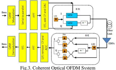
Simulink of Coherent Optical OFDM System
The overall system is shown in Fig. 3. Transmitter has two main functions. The first block is a block ODFM, which is supposed to create the OFDM signal in electrical domain. The second block is the Mach-Zehnder external modulation of electrical signals into optical signals corresponding to the two components I - Q. The Q is phase-shifted 90 degrees. The signals are combined and launched into the fiber.
Fig.3. Coherent Optical OFDM System
Output waveform when the signal is transmitted over optical fibers is obtained by solving equations (2). There are many methods to solve this equation, the common approach is to use a split-step Fourier method. The idea of this method is to divide the fiber into smaller sections with a length of about 200m to 500m. On the small stage, assuming that the effect of linear and nonlinear effects are independent of each other.
The receiver is responsible for converting signals from optical to electrical. In particular, local oscillator frequency LO created equal frequency of the transmitter laser. Optical signal to the receiver is separated into two components I, Q. Which go to the balanced receiver. The structure of the balanced receiver includes two photo-detectors. The two photo-detectors will increase 3 dB gain compared to the detector only a photo-detector. Electrical signal will be put in OFDM receiver. This block has the function to do the opposite steps at the transmitter to receive transmitted bit sequence.
V. S
IMULATION ANDE
XPERIMENTALP
LATFORMH.
Hardware Integrated Platform
The OFDM signals are monitored by the software platform SignalTap integrated in the hardware system, in particular the FPGA-based section. The results obtained are then displayed on a computer.
In order to study the functions and performances of each block of the system as described above we monitor and accumulated data at the input and output of each block. Delay adjustments are made to compensate for the data accumulation. This section presents the experimental results obtained including the monitoring of the spectra of OFDM system via an external spectrum analyzer.
Fig.4. Transmitted signals before and after adding cyclic prefix (a) component without cyclic prefix (b)
I-component with cyclic prefix.
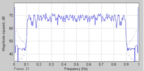
Fig.5. Spectra of noiseless OFDM signals as obtained on MATLAB Simulink (I-component). Normalized frequency.
Thus the common complex amplitude signals are used to represent the envelope of the signals. The phase of the carrier is included as the complex part of the amplitude. Spectra of OFDM signals are observed at the output of the DAC (Fig. 5).
I.
MATLAB Simulink of Coherent Optical OFDM
System
OFDM signal is modulated by the Mahnch-Zender (MZ) modulators for transmission on optical fiber. For optical guided wave channel the distortion is mainly due to chromatic and polarization dispersion effects and nonlinear self phase modulation effects [2]. The receiver uses two optical coherent detectors which serve as an optical-to-electrical OFDM I/Q converter before being sampled by the ADC.
The system is demonstrated for a transmission up to 640 km of standard-single-mode-fiber (SSMF) without dispersion compensation at 40Gb/s and 100Gb/s. We apply commonly used system parameters for our simulation: 8 spans, 80 km span distance, fiber chromatic dispersion of 3.56 ps/nm/km, 0.2 dB/km loss, and a nonlinear coefficient of 2.6×10⁻²⁰m2/W[8]. The fiber span loss is compensated by an EDFA with a gain of 16 dB and noise figure of 6 dB.
Figure 6 shows that BER versus fiber transmission distance of SSMF without dispersion compensation at the optimal optical launch power. The optimal optical launch power is about 9dBm. The system is demonstrated for a transmission up to 640 km of standard-single-mode-fiber
Fig.6. BER versus fiber length
VI. C
ONCLUDINGR
EMARKSIn this paper, we have demonstrated an OFDM communication platform using both MATLAB Simulink and software development of an FPGA-based development hardware. We have shown the principle and performance of systematic blocks of the systems for generation of OFDM symbols, mapping to QPSK symbols with possibility of upgrading to 16-QAM, models of transmission medium. The models are integrated into MATLAB development platform for simulation of OFDM signals transmission through optically amplified multi-span optical fiber communication systems for ultra-long transmission without using dispersion compensating modules. The models presented in this paper are currently modified to combat peak to average power ratio (PAPR). These works will be reported in the future.
R
EFERENCES[1] S. Chandrashekar and X. Liu “Enabling components for future high speed coherent optical communications”, Conference on
Optical Communications, LA., CA, USA, March, 2011. [2] LN Binh, “Digital Optical Communications”, CRC Press
Fraancis and Taylor Grp, Fl. USA, 2009.
[3] J. García, R. Cumplido, “On the design of an FPGA-Based OFDM modulator for IEEE 802.16-2004”, Proc. Int. Conf. Reconfigurable Comp. FPGAs, ReConFig 2005, pp. 1-4, 2005. [4] K.-C. Chang and G.E. Sobelman, “FPGA-Based Design of a
Pulsed-OFDM System”, Proc. APCCAS 2006, IEEE Asia Pacific Conf. Circ. Syst, 2006.
[5] Đang L.K., Nguyen T.A., Bui H.P., Nguyen H.P., “Hardware implementation of OFDM systems, J. Dev. and Res. on Sc. and Tech., Pub. Univ. of Natural Sc., HCM City, 2009.
[6] A. Peled, and A. Ruiz,“Frequency Domain Data Transmission Using Reduced Computational Complexity Algorithms,” Proc. IEEE International Conf. Acoustics, Speech, and Sig. Proc. (ICASSP’80), pp. 964-967, 1980.
[7] Hongchun Bao, William Shieh, “Transmission simulation of
coherent optical OFDM signals in WDM systems”, Optical
Society of America, Vol. 15, No. 8, pp.4410-pp.4418, 2007 [8] L.N. Binh, “MATLAB Simulink Modeling of Raman Hybrid
Amplification For Long Distance Hut-Skipped Undersea Optical Fiber Transmission Systems”,Opt. Eng., vol. 48, No. 10, pp. 105005-1 to 105005-12, 2009.
(a) (b)
(a)
[10] S. Hara, Ramjee Prasad,“Multicarrier Techniques for 4G Mobile Communications”, Artech House, 2003.
[11] M. Barkat, “Signal Detection and Estimation”,Norwood, MA: Artech House Inc., 2005.
AUTHOR PROFILE
Dang Le Khoa
graduated B.E. and M.Sc. in radio physics and electronics from the University of Science, Vietnam National University of HoChiMinh-City (VNU-HCM), Vietnam. He is lecturer and Head of Department of Telecommunications and Networks, University of Science, VNU-HCM. His current research interest is in the field of wireless and optical communication systems and digital signal processing for telecommunications.
Nguyen Thi Hong Thu
is a teacher’s assistant of Electronics and
Telecommunications Department, University of Science, VNU-HCM, Vietnam. She is a master student of Electronics Technique –
Telecommunications and Networking. She is interested in wireless communications systems and optical communications.
Nguyen Thanh Tu
received the B.S. degree in electronics and telecommunication from HCM University of Science, Vietnam in 2010. He is currently with Faculty of Electronics and Telecommunication, HCM University of Science, Vietnam, where he is a RA. He is also pursuing the M.Sc degree in electrical engineering. His area of interest includes signal processing for wireless communication systems, MIMO, cognitive radio network, optical system.