Optimisation Machining Process Parameters
in Wire Cut EDM
Manikandan.D1, Gokul Raja S 2, Joel J 3 , Karthick S 4, Karthikeyan A S 5
Assistant Professor, Department of Mechanical Engineering, Dhanalakshmi Srinivasan College of Engineering,
Perambalur, India1
UG Scholar, Department of Mechanical Engineering, Dhanalakshmi Srinivasan College of Engineering, Perambalur,
India2,3,4,5
ABSTRACT: The wire electrical discharge machining (WEDM) is one of the latest non-traditional machining processes, based on thermoelectric energy between the work piece and wire. The performance of the process, to a large extent, depends on the tool material, work piece material &manufacturing method of the tool. A suitable selection of tool can reduce the cost of machining. The performance of WEDM is find out on the basis of Material Removal Rate(MRR), KERF Width and Surface Roughness (SR). The important machining parameters of EDM which affecting on the performance parameters are discharge current, pulse on time, pulse off time, arc gap, flushing pressure, servo voltage and wire tension. Taguchi design of experiments is used to conduct experiments by varying the parameters servo voltage, pulse on time and pulse off time. The process performance is measured in terms of Material Removal Rate (MRR), KERF Width and Surface Roughness (Ra). In this project WEDM experiment using 0.25 mm diameter copper wire(Zinc coated) & EN-31 tool Steel work piece has been done for optimizing MRR, KERF width, Surface finish and reducing cost of manufacturing. By using multi objective optimization technique grey relational theory, the optimal value is obtained for MRR, surface roughness and KERF width.
1. INTRODUCTION
Wire EDM is an electrical discharge machining process with a continuously moving conductive wire as tool electrode. The mechanism of metal removal in wire electrical discharge machining (WEDM) involves the complex erosion effect of electric sparks generated by a pulsating direct current power supply between two closely spaced electrodes in dielectric liquid. The high energy density erodes material from both the wire and work piece by local melting and vaporizing. Because the new wire keeps feeding to the machining area, the material is removed from the work piece with the moving of wire electrode. Eventually, a cutting shape is formed on the work piece by the prog2ammed moving trajectory of wire electrode. The equipment is extensively used in making dies and molds
II. LITERATURE REVIEW
prime importance. Rough cutting operation in WEDM is treated as a challenging one because improvement of more than one machining performance measures viz. metal removal rate (MRR), surface finish (SF) and cutting width (kerf) are sought to obtain a precision work. Using Taguchi’s parameter design, significant machining parameters affecting the performance measures are identified as discharge current, pulse duration, pulse frequency, wire speed, wire tension, and dielectric flow. It has been observed that a combination of factors for optimization of each performance measure is different. In this study, the relationship between control factors and responses like MRR, SF and kerf was established by means of nonlinear regression analysis, resulting in a valid mathematical model. Finally, genetic algorithm, a popular evolutionary approach, was employed to optimize the wire electrical discharge machining process with multiple objectives. The study demonstrated that the WEDM process parameters can be adjusted to achieve better metal removal rate, surface finish and cutting width simultaneously. M.J. Haddad and A. Fadaei Tehrani [5],made material removal rate (MRR) study in the cylindrical wire electrical discharge turning (CWEDT) process- As using wire EDM (WEDM) technology, complicated cuts can made through difficult to machine electrically conductive components, the cylindrical wire electrical discharge turning (CWEDT) process was developed to generate precise cylindrical forms on complicate, hard and difficult to machine materials. The hardness and strength of the work material are no longer the dominating factors that affect the tool wear and hinder the machining process. The right selection of machining conditions is the most important aspect to take into consideration in process related to the WEDM operations. This paper presented an investigation on the effects of machining parameters on material removal rate (MRR) in cylindrical wire electrical discharge turning (CWEDT) process. In this research, CWEDT of AISI D3 (DIN X210Cr12) tool steel was studied by using of statistical design of experiment (DOE) method. Nihat Tosun and Can Cogun [6], An investigation on wire wear in WEDM- In this study, the effect of cutting parameters on wire electrode wear was investigated experimentally in wire electrical discharge machining (WEDM). The experiments were conducted under different settings of pulse duration, open circuit voltage, wire speed and dielectric fluid pressure. Brass wire of 0.25 mm diameter and AISI 4140 steel of 10 mm thickness were used as tool and workpiece material. It is found experimentally that the increasing pulse duration and open circuit voltage increase the wire wear ratio (WWR) whereas the increasing wire speed decreases it. The variation of workpiece material removal rate and average surface roughness were also investigated in relation to the WWR. The variation of the WWR with machining parameters was modelled statistically by using regression analysis technique. The level of importance of the machining parameters on the WWR was determined by using analysis of variance (ANOVA) method. Effect of process parameters on material removal rate in wire EDM [H.singh, R.Garg] The effect of various process parameters of WEDM like pulse on time (Ton ),pulse off time(Toff),gap voltage(SV),peak current (IP),wire feed (WF) ,wire tension (WT) have beem investigated.The paper reveals there influence on the MRR of hot die steel(H-11).one variable ata time approach is used .the experiments were carried out on Electronica Sprint cut WEDM. Nihat Tosun et.al [8] investigated on the effects and optimization of machining parameters on the (cutting width) and material removal rate (MRR) in wire EDM operation .the experiments were conducted under various wire speed ,open circuit voltage ,pulse duration and dielectic flushing pressure .the design of experiment was done using Taguchi Method. A mathematical model was developed correlating the various wire EDM parameters like peak current, duty factor, wire tension and water present by Hewidy et al. [9].the variation of above parameters were correlated with MRR.
III. PROBLEM IDENTIFICATION
Experiments are carried out using orthogonal array by varying pressure, standoff distance, Abrasive flow rate and Traverse rate respectively. Experimental results are provided to verify this approach..
IV. METHODOLOGY
4.1TAGUCHI PRINCIPLE
A well planned set of experiments, in which all parameters of interest are varied over a specified range, is a much better approach to obtain systematic data. Mathematically speaking, such a complete set of experiments ought to give desired results. Usually the number of experiments and resources (materials and time) required are prohibitively large. Often the experimenter decides to perform a subset of the complete set of experiments to save on time and money! However, it does not easily lend itself to understanding of science behind the phenomenon. The analysis is not very easy (though it may be easy for the mathematician/statistician) and thus effects of various parameters on the observed data are not readily apparent. In many cases, particularly those in which some optimization is required, the method does not point to the BEST settings of parameters. A classic example illustrating the drawback of design of experiments is found in the planning of a world cup event, say football. While all matches are well arranged with respect to the different teams and different venues on different dates and yet the planning does not care about the result of any match (win or lose)!!!! Obviously, such a strategy is not desirable for conducting scientific experiments (except for coordinating various institutions, committees, people, equipment, materials etc.).
4.1.2 PROPERTIES OF AN ORTHOGONAL ARRAY
The orthogonal arrays have the following special properties that reduce the number of experiments to be conducted.
1. The vertical column under each independent variables of the above table has a special combination of level settings. All the level settings appear an equal number of times. For L9 array under variable 4, level 1, level 2 and level 3 appears thrice. This is called the balancing property of orthogonal arrays.
2. All the level values of independent variables are used for conducting the experiments.
3. The sequence of level values for conducting the experiments shall not be changed. This means one cannot conduct experiment 1 with variable 1, level 2 setup and experiment 4 with variable 1, level 1 setup. The reason for this is that the arrays of each factor columns are mutually orthogonal to any other column of level values. The inner product of vectors corresponding to weights is zero. If the above 3 levels are normalized between -1 and 1, then the weighing factors for level 1, level 2 , level 3 are -1 , 0 , 1 respectively. Hence the inner product of weighing factors of independent variable 1 and independent variable 3 would be (-1 * -1+-1*0+-1*1)+ (0*0+0*1+0*-1) + (1*0+1*1+1*-1) =0
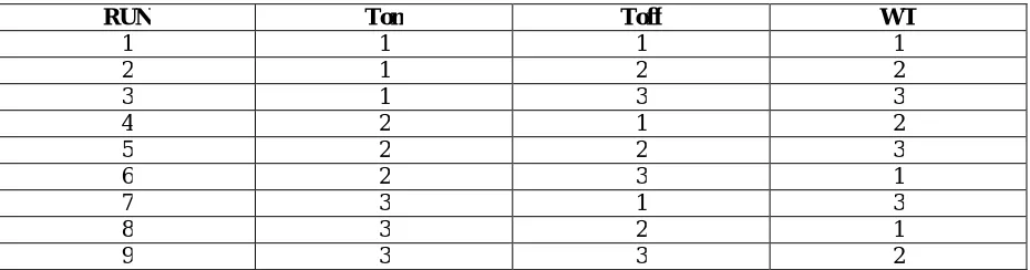
Table 1.1 L9 Orthogonal Array
RUN Ton Toff WT
1 1 1 1
2 1 2 2
3 1 3 3
4 2 1 2
5 2 2 3
6 2 3 1
7 3 1 3
8 3 2 1
9 3 3 2
4.2 EXPERIMENTAL SETUP
A plate of 50 mm ×50 mm size and thickness 12mm of EN31 die steel was taken. It was subjected to a standard hardening cycle and it has a hardened at the range of 25-35HRC before heat treatment,35-45HRC after heat treatment.
Standard of wire diameter is 0.25 mm
In each experiment, 300×250×200 mm (bed size)
The work material size selected as 50×50×12 mm,
The reason for selecting this size is to obtain the results for wide range. During this process, the wire diameter is kept constant
One surface of the work piece was then ground on a surface grinder to remove surface irregularities and minor scaling. The hardness of this surface was measured on Rockwell Hardness Tester C scale using a diamond cone. After mounting the work piece and one of the electrodes on the machine, the depth of machining was set at 25mm. The work piece was machined with 3 A discharges current and other standard machine settings. The time of machining was recorded in minutes and final weights of the work piece were taken. The machining cycle was repeated for the next value of discharge current. Similarly, the observations were made for the other two electrodes.
For each electrode material, the effect of variation in discharge current was studied on output parameters, namely, material removal rate (MRR), machined surface roughness. Surface roughness readings were taken on the bottom surface of the machined cavity. Surface roughness was measured on Surf test equipment giving Ra value in microns.
4.3 ELECTRODE MATERIALS
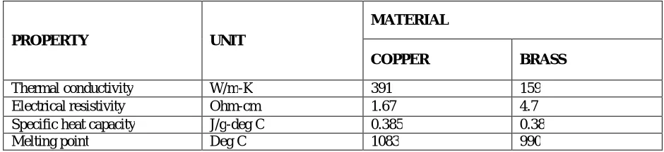
Electrode material has a significant influence on important output parameters, such as, material removal rate, surface roughness and dimensional accuracy. Copper and brass are two commonly used EDM electrode materials in the industry because these materials have high melting temperature and excellent electrical and thermal conductivity. Copper can be easily machined to any shape, suffers less wear, has good thermal conductivity, and is economical. Brass is inexpensive and very easy to machine, but it has high electrode wear. It is often used for tubular electrodes in specialized small hole EDM drilling machines where high wear is acceptable. Electrodes made from special powders by using powder metallurgy technology have been used to modify EDM surfaces in recent years and excellent wear and corrosion resistance has been achieved under specific machining conditions. However, this technique is yet to gain wide acceptance.
TABLE 1.2 Properties of Work Material And Brass Electrode
The electrodes for EDM process usually are made of graphite, brass, copper and copper-tungsten alloys. Design considerations for EDM process are as follows:
Deep slots and narrow openings should be avoided.
The surface smoothness value should not be specified too fine.
Rough cut should be done by other machining process. Only finishing operation should be done in this process as MRR for this process is low.
PROPERTY UNIT
MATERIAL
COPPER BRASS
Thermal conductivity W/m-K 391 159
Electrical resistivity Ohm-cm 1.67 4.7
Specific heat capacity J/g-deg C 0.385 0.38
4.4 Work material (EN31 die steel)
The work material chosen for this experimental work is EN31 die steel
It is one of the most widely used die steel material for the manufacture.
press tools cutting dies and punches for blanking, trimming, flanging and forming operations
For Job preparation for wire EDM process includes Metal cutting, shaping, Grinding and in all four sides
TABLE 1.3 Chemical Composition of EN31 Die Steel
S.NO ELEMENT COMPOSITION
IN WEIGHT (%)
1 C 0.033
2 Si 0.017
3 Mn 0.51
4 S 0.009
5 P 0.013
6 Ni 4.16
7 Cr 1.44
8 Mo 0.031
V. MACHINING PARAMETER SELECTION
In this study, a Reciprocating Wire-cut EDM machine, Electronic make, FA103 (MITSUBISHI) model was used as the experimental machine. Cylindrical hard copper wire with a diameter of 0.25 mm was used as an electrode to erode a work piece of EN30 die steel plate of the thickness of 30mm.
The work piece and electrode were separated by a moving dielectric fluid i.e. blend of distilled water and kerosene oil in a ratio of 5:1. Machining experiments for determining the optimal machining parameters were carried out by setting: gap voltage in the range of 60 to 80V, wire feed in the range of 3.5-13.1 mm/min; a gap current in the range of 1-3 A, a duty factor in the range of 0.25 to 0.75. To perform the
Experimental design, three levels of the machining parameters (gap voltage, wire feed, gap current, and duty factor) were selected and are shown in Table 1. The initial machining parameters were selected as follows: gap voltage of 60V, wire feed of 3.5 mm/min, a gap current of 1A, a duty factor of 0.75.
The effect of various input parameters on material removal rate (MRR) and surface roughness (Ra) is discussed below
5.1 INPUT PARAMETER SELECTION
Pulse on time (131-110µs)
Pulse off time (26-36 µs)
Wire tension (6-11 kgf)
Table 1.4 Input Parameters and their Level
Symbol Machining parameter unit Level Ⅰ Level Ⅱ Level Ⅲ
TON Pulse on time µs 110(A) 120(B) 131(C)
TOFF Pulse off time µs 26 (X) 36 (Y) 46(Z)
WT Wire Tension Kgf 6(α) 8(β) 11(γ)
5.2 OUTPUT PARAMETERS
1. Material removal rate (kg/min.) 2. Surface roughness (Ra) (µm) 3. Kerf or cutting width (mm)
5.3 INFLUENCE OF MACHINING PARAMETER’S RESPONSES
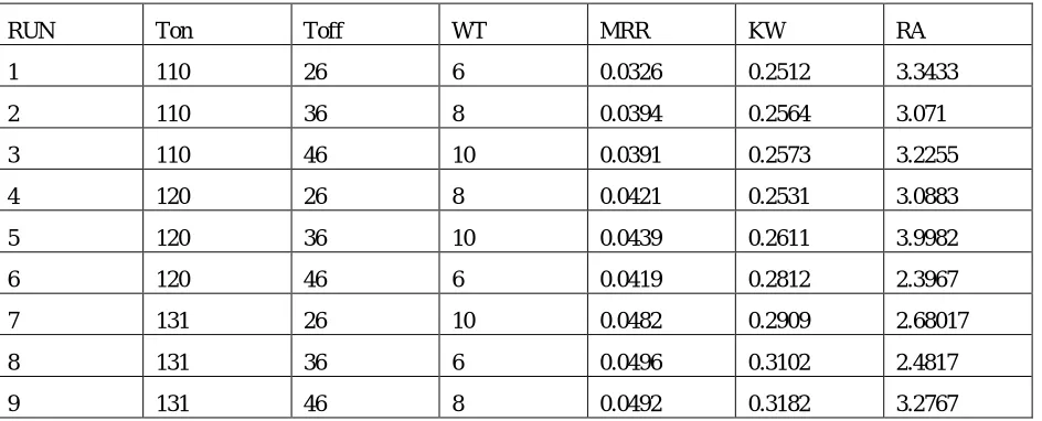
Table No 1.5 L9 Array for WEDM with Parameters
RUN Ton Toff WT MRR KW RA
1 110 26 6 0.0326 0.2512 3.3433
2 110 36 8 0.0394 0.2564 3.071
3 110 46 10 0.0391 0.2573 3.2255
4 120 26 8 0.0421 0.2531 3.0883
5 120 36 10 0.0439 0.2611 3.9982
6 120 46 6 0.0419 0.2812 2.3967
7 131 26 10 0.0482 0.2909 2.68017
8 131 36 6 0.0496 0.3102 2.4817
VI. RESULTS AND DISCUSSION
131 120
110 -3.2
-3.3
-3.4
-3.5
-3.6
46 36
26 6 8 10
Ton
M
e
a
n
o
f
S
N
r
a
ti
o
s
Toff WT
Main Effects Plot for SN ratios
Data Means
Signal-to-noise: Nominal is best (10×Log10(Ybar^2/s^2))
131 120
110 1.20
1.15
1.10
1.05
1.00
46 36
26 6 8 10
Ton
M
e
a
n
o
f
M
e
a
n
s
Toff WT
Main Effects Plot for Means
Taguchi Analysis: MRR, KW, RA versus Ton, Toff, WT
Response Table for Signal to Noise Ratios Nominal is best (10×Log10(Ybar^2/s^2))
Level Ton Toff WT 1 -3.626 -3.490 -3.263 2 -3.493 - 3.450 -3.501 3 -3.185 - 3.364 -3.540 Delta 0.442 0.127 0.277 Rank 1 3 2
Response Table for Means
Level Ton Toff WT 1 1.168 1.114 1.021 2 1.156 1.168 1.155 3 1.056 1.098 1.205 Delta 0.112 0.070 0.184 Rank 2 3 1
VII. CONCLUSION
In the present work experiments are carried out for Material removal rate ,surface roughness and Kerf Width with variables as pulse on time, pulse off time and wire tension. There are nine experimental reading taken for all variables to conduct the parametric study
Taguchi orthogonal array method is done to find the optimum parameter levels. It is found that pulse on time at level 3(131s) ,pulse off time at level 2(36 s),wire tension at level 1(6kgf) are the best process parameters for the MRR ,KERF width and surface roughness. process parameters do not have some little effect for every response. Significant parameters and its percentage contribution changes as per the behaviours of the parameter with objective response.
REFERENCES
1. Surface modification by electrical discharge machining: A review’ ” Journal on material processing Technology” (2009) by Sanjeev Kumara, Rupinder Singh, T.P. Singh, and B.L. Sethi.
2. Effects of wire-EDM machining variables on surface roughness of newly developed DC 53 die steel: Design of experiments and regression model, “Journal on material processing Technology” (2007) by K. Kanlayasiri, S. Boonmung.
3. Modeling the machining parameters of wire electrical discharge machining of Inconel 601 using RSM, “Journal on material processing Technology” (2005) by M.S. Hewidy, T.A. El-Taweel, and M.F. El-Safty.
4. Influence of the type and grain size of the electro-conductive phase on the Wire-EDM performance of ZrO2 ceramic composites, “Manufacturing Technology” (2008) by B. Lauwers, K. Brans, W. Liu,
5. J. Vleugels, S. Salehi, K. Vanmeensel.
6. Investigation of the effect of process parameters on the formation and characteristics of recast layer in wire-EDM of Inconel 718, “Material science and engineering” (2009) by Thomas R. Newton, Shreyes N. Melkote, Thomas R.Watkins, Rosa M. Trejo, and Laura Reister.
7. Residual stresses and white layer in electric discharge machining (EDM), “Journal on Applied surface science” (2007) by Bulent Ekmekci.
8. Modeling and optimization of wire electrical discharge machining of TiAl in trim cutting operation, “Journal on material processing Technology” (2008) by S. Sarkar, M. Sekh, S. Mitra, B. Bhattacharyya.