555-233-124
Comcode 108678723
Issue 1
April 2000
Release 8.2
Every effort was made to ensure that the information in this book was complete and accurate at the time of printing. However, information is subject to change.
Your Responsibility for Your System’s Security
Toll fraud is the unauthorized use of your telecommunications system by an unauthorized party, for example, persons other than your com-pany’s employees, agents, subcontractors, or persons working on your company’s behalf. Note that there may be a risk of toll fraud associated with your telecommunications system and, if toll fraud occurs, it can result in substantial additional charges for your telecommunications services.
You and your system manager are responsible for the security of your system, such as programming and configuring your equipment to pre-vent unauthorized use. The system manager is also responsible for reading all installation, instruction, and system administration docu-ments provided with this product in order to fully understand the fea-tures that can introduce risk of toll fraud and the steps that can be taken to reduce that risk. Lucent Technologies does not warrant that this product is immune from or will prevent unauthorized use of com-mon-carrier telecommunication services or facilities accessed through or connected to it. Lucent Technologies will not be responsible for any charges that result from such unauthorized use.
Lucent Technologies Fraud Intervention
If you suspect that you are being victimized by toll fraud and you need technical support or assistance, call Technical Service Center Toll Fraud Intervention Hotline at 1 800 643-2353 or contact your local Lucent representative.
Federal Communications Commission Statement
Part 15: Class A Statement. This equipment has been tested and
found to comply with the limits for a Class A digital device, pursuant to Part 15 of the FCC Rules. These limits are designed to provide reason-able protection against harmful interference when the equipment is operated in a commercial environment. This equipment generates, uses, and can radiate radio-frequency energy and, if not installed and used in accordance with the instructions, may cause harmful interfer-ence to radio communications. Operation of this equipment in a resi-dential area is likely to cause harmful interference, in which case the user will be required to correct the interference at his own expense.
Part 68: Network Registration Number. This equipment is registered
with the FCC in accordance with Part 68 of the FCC Rules. It is identi-fied by FCC registration number AS593M-13283-MF-E.
Part 68: Answer-Supervision Signaling. Allowing this equipment to
be operated in a manner that does not provide proper answer-supervi-sion signaling is in violation of Part 68 Rules. This equipment returns answer-supervision signals to the public switched network when:
• Answered by the called station • Answered by the attendant
• Routed to a recorded announcement that can be administered by the CPE user
• A reorder tone is received
Canadian Department of Communications (DOC) Interference Information
This digital apparatus does not exceed the Class A limits for radio noise emissions set out in the radio interference regulations of the Canadian Department of Communications.
Le Présent Appareil Nomérique n’émet pas de bruits radioélectriques dépassant les limites applicables aux appareils numériques de la class A préscrites dans le reglement sur le brouillage radioélectrique édicté par le ministére des Communications du Canada.
Trademarks
See the preface of this document.
Ordering Information
Call: Lucent Technologies BCS Publications Center
Voice 1 800 457-1235 International Voice 317 322-6416 Fax 1 800 457-1764 International Fax 317 322-6699
Write: Lucent Technologies BCS Publications Center 2855 N. Franklin Road
Indianapolis, IN 46219
Order: Document No. 555-233-124 Comcode 108678723 Issue 1, April 2000
For additional documents, refer to the section in “About This Docu-ment” entitled “Related Resources.”
You can be placed on a standing order list for this and other documents you may need. Standing order will enable you to automatically receive updated versions of individual documents or document sets, billed to account information that you provide. For more information on stand-ing orders, or to be put on a list to receive future issues of this docu-ment, contact the Lucent Technologies Publications Center.
European Union Declaration of Conformity
The “CE” mark affixed to the DEFINITY® equipment described in this book indicates that the equipment conforms to the following Euro-pean Union (EU) Directives:
• Electromagnetic Compatibility (89/336/EEC) • Low Voltage (73/23/EEC)
• Telecommunications Terminal Equipment (TTE) i-CTR3 BRI and i-CTR4 PRI
For more information on standards compliance, contact your local dis-tributor.
Comments
To comment on this document, return the comment card at the front of the document.
Acknowledgment
Contents
Contents iii
About This Book v
■ Overview vi
■ Organization vi
■ Conventions Used in This Book viii
■ How to Comment on This Document ix
■ Resources ix
■ Antistatic Protection xii
■ Remove/Install Circuit Packs xii
■ Security xii
■ Trademarks xii
■ Standards Compliance xiii
■ LASER Product xiv
■ Electromagnetic Compatibility Standards xiv
■ Federal Communications Commission Statement xvi
1
Preparing for Installation and Upgrades 1-1■ Request Address Information 1-2
■ Review Configuration and Equipment 1-3
■ Determine ATM Switch Suitability 1-9
■ Schedule Installation or Upgrade 1-14
2
Installing a DEFINITY ECSATM-CES 2-1
■ Equipment Installation 2-1
■ NAA7 Board (csi/c models only) 2-3
3
Installing a DEFINITY ECSATM-PNC 3-1
■ Equipment Installation 3-1
■ Synchronization Installation and Testing 3-3
■ ATM Network Duplication 3-32
4
Upgrading to ATM-PNC 4-1■ Upgrade paths 4-1
■ Preparation 4-2
■ R6.3r ATM-PNC to R8r ATM-PNC 4-13
■ R7r ATM-PNC to R8r ATM-PNC 4-14
■ Screens and Tables 4-21
5
Administering ATM-PNC andATM-CES 5-1
■ Accessing Switches for Administration 5-1
■ Acquiring ATM Addresses 5-2
■ Administering ATM Switch 5-4
■ Administering DEFINITY ECS 5-4
■ Final Checklist and Test 5-34
6
Troubleshooting 6-1■ Contact information 6-2
■ Alarms and errors 6-3
■ Troubleshooting ATM-CES 6-5
■ Troubleshooting ATM-PNC 6-16
A
Baselining the Customer’s Configuration A-1■ ATM Switch Administration A-1
■ Interconnections A-2
■ DEFINITY ECS Administration Worksheet A-3
B
ATM Switch Feature Interactions B-1■ Location-related Interactions B-1
■ Features Supported B-7
■ Features Not Supported B-10
■ Delay Interactions B-11
■ ATM Feature Interactions B-19
■ Cross-product Compatibility B-24
GL
Glossary and Abbreviations GL-1About This Book
This book provides procedures for installing ATM switches and upgrading
existing DEFINITY® Enterprise Communications Servers to a Release 8.2
ATM-PNC or ATM-CES. It specifically covers
■ Installing a new DEFINITY ECS that uses ATM-PNC
■ Replacing the center stage switch (CSS), the central interface between
the PPN and EPNs, with ATM-PNC
■ Upgrading Release 6.3 and Release 7 DEFINITY ATM-PNC to Release 8.2
ATM-PNC
■ Adding ATM-CES
The information in this book is intended for use by
■ Lucent and channel partner trained field installation and maintenance
personnel
■ Technical Services Center (TSC) and Global Service Organization (GSO)
personnel
■ InterNetwork Systems (INS) engineers and technicians
■ Sales and Design Support Center (SDSC) personnel
■ Data Services Support Center (DSSC)
■ Sales associates
Overview
The DEFINITY ATM (asynchronous transfer mode) combines portions of the DEFINITY platform with an ATM switch platform that meets specific criteria. DEFINITY ATM offers both intraswitch and interswitch ATM solutions. The intraswitch solution is called the ATM port network connectivity, or ATM-PNC, and the interswitch solution is called ATM circuit emulation service, or ATM-CES. ATM-PNC is only available on the R6.3r or later platform.
ATM-PNC provides an alternative to either the direct connect or center stage switch configurations for connecting the processor port network (PPN) to one or more expansion port networks (EPNs). ATM-PNC is available with four DEFINITY ECS reliability options—standard, high, ATM network duplication, and critical. Customers must choose whether they want direct connect, CSS, or ATM-PNC. It is not possible to mix configurations in the same R8r platform.
ATM-CES lets the DEFINITY ECS emulate an ISDN-PRI trunk on an ATM facility. These virtual trunks can serve as integrated access, tandem, or tie trunks. ATM-CES emulates up to 8 ISDN spans on a single OC-3/STM-1 ATM interface.
ATM wide area network (ATM-WAN) extends the port network connectivity beyond a single ATM switch over large distances. This allows you to use either a private ATM network, public WAN or a combination of both. Several networked ATM devices can be used as effectively as a single ATM switch for inter-port network connectivity.
The DEFINITY ECS switch can connect through several ATM switch types, many of which are sold through Lucent’s InterNetworking Systems (INS) channel, formerly know as DNS. Also, DEFINITY ECS switches are designed to work seamlessly with non-Lucent ATM switches that meet ATM standards set by the European Union.
For a current list of Lucent switches, go to the Infohub Web site
(http://infohub.mt.lucent.com/) and select Product Index. Examples include the
following equipment:
■ Lucent Cajun M770 ATM switch
■ Lucent PacketStar AC 60 or PSAX1250 access concentrators
Organization
This book contains 6 chapters and 2 appendices:
■ Chapter 1, ‘‘Preparing for Installation and Upgrades’’ describes the
preparation necessary before an installation and upgrade, including — network design considerations, including SVCs generated and
— interactions among various Lucent organizations to prepare the customer site for equipment, translations, and scheduling upgrades and new installations
— calculating the suitability of various Lucent ATM switches
■ Chapter 2, ‘‘Installing a DEFINITY ECS ATM-CES’’ provides a procedure
for
— hardware installation: ATM circuit packs and the ATM switch. — cabling (I/O connector, fiber optic cables)
■ Chapter 3, ‘‘Installing a DEFINITY ECS ATM-PNC’’ provides a procedure
for
— hardware installation: ATM circuit packs, T1 or E1 synchronization splitter, the ATM switch.
— cabling (I/O connector, fiber optic cables) — ATM network duplication
■ Chapter 4, ‘‘Upgrading to ATM-PNC’’ describes the preparation and
various upgrade paths for the following upgrades: — center stage switch to Release 8 ATM-PNC
— Release 6.3 and Release 7 DEFINITY ATM-PNC to Release 8 ATM-PNC
■ Chapter 5, ‘‘Administering ATM-PNC and ATM-CES’’ provides the
step-by-step procedures for administering — ATM port network connectivity (ATM-PNC) — ATM circuit emulation service (ATM-CES)
■ Chapter 6, ‘‘Troubleshooting’’ describes troubleshooting scenarios and
offers suggestions for isolating, fixing, and clearing DEFINITY ECS alarms and errors for
— DEFINITY ECS administration — ATM-related synchronization — ATM switch administration
■ Appendix A, ‘‘Baselining the Customer’s Configuration’’ provides a
worksheet to log the translations and administration information for — DEFINITY ECS
— Lightwave interface units
■ Appendix B, ‘‘ATM Switch Feature Interactions’’ offers a quick-reference
Conventions Used in This Book
Typographic
■ Information you type at the access terminal is shown in the following
typeface: list system-parameters maintenance.
■ Variables are shown in the following typeface: number.
■ Field names and information displayed on the access terminal screen is
shown in the following typeface: login.
■ Keyboard keys are shown in the following typeface: Enter.
Systems and circuit packs
■ The word “system” is a general term encompassing Release 8 and
includes references to the DEFINITY Enterprise Communications Server models: Release 8r, Release 8si, Release 8csi, and Release 8c.
■ DEFINITY Enterprise Communications Server is abbreviated as DEFINITY
ECS.
■ Circuit pack codes (for example, TN780 or TN2182B) are shown with the
minimum acceptable alphabetic suffix (like the “B” in the code TN2182B). Generally, an alphabetic suffix higher than that shown is also acceptable. However, not every vintage of either the minimum suffix or a higher suffix code is necessarily acceptable.
■ The term “ASAI” is synonymous with the newer CallVisor ASAI.
Admonishments
Admonishments in this book have the following meanings:
!
CAUTION:
This sign is used to indicate possible harm to software, possible loss of data, or possible service interruptions.
!
WARNING:
This sign is used where there is possible harm to hardware or equipment.
!
DANGER:
Physical dimensions
■ All physical dimensions in this book are in English units (feet [ft]) followed
by metric (centimeter [cm]) in parenthesis.
■ Wire gauge measurements are in AWG followed by the diameter in
millimeters in parenthesis
How to Comment on This Document
Lucent Technologies welcomes your feedback. Your comments are of great value and help improve our documentation.
■ Please fill out the reader comment card at the front of this manual and
return it.
■ If the reader comment card is missing, FAX your comments to
1-303-538-1741 or to your Lucent Technologies representative, and mention this document’s name and number, DEFINITY Enterprise Communication Server Release 8 ATM Installation, Upgrade, and Administration, 555-233-124, Issue 1.
■ Email your comments to [email protected]
Resources
Related Books
The following books are useful for system-related information:
■ DEFINITY Enterprise Communications Server Release 8 Administration for
Network Connectivity
■ DEFINITY Enterprise Communications Server Release 8 System
Description
■ DEFINITY Enterprise Communications Server Release 8 Maintenance for
R8r
■ DEFINITY Enterprise Communications Server Release 8 Maintenance for
R8si
■ DEFINITY Enterprise Communications Server Release 8 Maintenance for
R8csi
■ AT&T Network and Data Connectivity Reference
■ DEFINITY Enterprise Communications Server Release 8 Installation and
Test for Multicarrier Cabinets
■ DEFINITY Enterprise Communications Server Release 8 Installation and
■ DEFINITY Enterprise Communications Server Release 8 Installation,
Upgrades, and Additions for Compact Modular Cabinets
■ DEFINITY Enterprise Communications Server Release 8 Administrator’s
Guide
■ DEFINITY Enterprise Communications Server Release 8 Upgrades and
Additions for R8si
■ DEFINITY Enterprise Communications Server Release 8 Upgrades and
Additions for R8r
How to Order Books
In addition to this book, other description, installation and test, maintenance, and administration books are available. A complete list of DEFINITY books can be found in the Business Communications System Publications Catalog.
This book and any other DEFINITY books can be ordered directly from the Lucent Technologies Business Communications System Publications Fulfillment Center at 1-317-322-6791 or toll free at 1-800-457-1235.
Other Resources
The following table lists Web sites containing more information on Lucent’s ATM switch activities.
Topic Location
Sales and marketing, design, administration, maintenance, provisioning, and upgrade (migration) activities
DEFINITY Solutions - ATM
http://www.bcs.lucent.com/sales_ market/definity/atm
General information on available Lucent ATM switches
Infohub
http://infohub.mt.lucent.com/
(available to Lucent personnel only) User manuals, installation guides,
release notes, and help files
Cajun Tech Pubs
Where To Call for Technical Support
Use the telephone numbers in Table 1 for the region in which the system is being
installed.
Table 1. Technical support contact numbers
Telephone Number
DEFINITY Helpline (feature administration and system applications)
1-800-225-7585
Lucent Technologies Toll Fraud Intervention 1-800-643-2353
Lucent Technologies National Customer Care Center (ATM customers)
1-800-242-2121
Lucent Technologies Corporate Security 1-800-822-9009
Streamlined Implementation (for missing equipment) 1-800-772-5409
USA/Canada Technical Service Center (ATM technicians) 1-800-248-1234
NetCare® Professional Services (NPS) 1-800-237-0016
International Technical Assistance (ITAC) 1-303-804-3777
Lucent Technologies Centers of Excellence
Asia/Pacific Regional Support Center 65-872-8686
Western Europe/Middle East/South Africa 44-1252-77-4800
Central/Eastern Europe 361-345-4334
Central/Latin America Caribbean 1-303-804-3778
Australia 61-2-9352-9090
Antistatic Protection
!
WARNING:
To minimize electrostatic discharge (ESD), always wear an authorized wrist ground strap when handling circuit packs or any components of a
DEFINITY System. Connect the strap to an approved ground such as an unpainted metal surface on the DEFINITY ECS switch.
Remove/Install Circuit Packs
!
CAUTION:
The control circuit packs with white labels cannot be removed or installed when the power is on. The port circuit packs with gray labels (older version circuit packs had purple labels) can be removed or installed when the power is on.
Security
To ensure the greatest security possible, Lucent Technologies offers services that can reduce toll fraud liabilities. Contact your Lucent Technologies representative for more security information.
Login security is an attribute of the DEFINITY ECS software. Advise customers that their existing passwords expire 24 hours after the upgrade. Also explain that the new passwords must conform to strict requirements.
System administrators must keep network addresses confidential. A PPN or any endpoint masquerading as a PPN on the ATM network can seize that EPN and control it if that EPN is not already connected to its proper PPN.
Trademarks
This document contains references to the following Lucent Technologies trademarked products:
■ ACCUNET®
■ AUDIX®
■ Callmaster®
■ CallVisor®
■ CONVERSANT®
■ DEFINITY®
■ MEGACOM®
■ SYSTIMAX®
■ TRANSTALK™
The following products are trademarked by their corresponding vendor:
■ Audichron® is a registered trademark of Audichron Company
■ LINX™ is a trademark of Illinois Tool Works, Inc.
■ Windows95/98/NT is a trademark of Microsoft Corporation
■ Music Mate® is a registered trademark of Harris Corporation
■ PagePac® is a registered trademark of Harris Corporation, Dracon
Division
■ Shockwatch® is a registered trademark of Media Recovery, Incorporated
■ Styrofoam® is a registered trademark of Styrofoam Corporation
■ Tiltwatch® is a registered trademark of Media Recovery, Incorporated
■ Zone Mate® is a registered trademark of Harris Corporation
Standards Compliance
The equipment in this document complies with:
■ ITU-T (Formerly CCITT)
■ ECMA ■ ETSI ■ IPNS
■ DPNSS
■ National ISDN-1
■ National ISDN-2
■ ISO-9000
■ ANSI
■ FCC Part 15 and Part 68
■ EN55022
■ EN50081
■ EN50082
■ UNI 3.1
■ CISPR22
■ Australia AS3260
■ IEC 825
■ IEC 950
■ UL1459
■ UL 1950
■ CSA C222 Number 225
■ TS001
■ ILMI 3.1
LASER Product
The DEFINITY ECS switch may contain a Class 1 LASER device (IEC 825 1993) if single-mode fiber optic cable is connected to a remote expansion port network (EPN). The laser device operates within the following parameters:
!
DANGER:
Use of controls or adjustments or performance of procedures other than those specified herein may result in hazardous radiation exposure.
Contact your Lucent Technologies representative for more information.
Electromagnetic Compatibility
Standards
This product complies with and conforms to the following:
■ Limits and Methods of Measurements of Radio Interference
Characteristics of Information Technology Equipment, EN55022 (CISPR22), 1993
■ EN50082-1, European Generic Immunity Standard
■ FCC Part 15
■ Australia AS3548
NOTE:
The DEFINITY system conforms to Class A (industrial) equipment. Voice terminals meet Class B requirements.
Power output Wavelength Mode field diameter
■ Electrostatic Discharge (ESD) IEC 1000-4-2
■ Radiated radio frequency field IEC 1000-4-3
■ Electrical Fast Transient IEC 1000-4-4
■ Lightning effects IEC 1000-4-5
■ Conducted radio frequency IEC 1000-4-6
■ Mains frequency magnetic field IEC 1000-4-8
■ Low frequency mains disturbance
The system conforms to the following:
■ Electromagnetic Compatibility General Immunity Standard, part 1;
Residential, Commercial, Light Industry, EN50082-1, CENELEC, 1991
■ Issue 1 (1984) and Issue 2 (1992), Electrostatic Discharge Immunity
Requirements (EN55024, Part 2) IEC 1000-4-2
■ Radiated Radio Frequency Field Immunity Requirements IEC 1000-4-3
■ Electrical Fast Transient/Burst Immunity Requirements IEC 1000-4-4
European Union Standards
Lucent Technologies Business Communications Systems declares that the DEFINITY equipment specified in this document bearing the “CE” mark conforms to the European Union Electromagnetic Compatibility Directives.
The “CE” (Conformité Europeénne) mark indicates conformance to the European Union Electromagnetic Compatibility Directive (89/336/EEC) Low Voltage Directive (73/23/EEC) and Telecommunication Terminal Equipment (TTE) Directive (91/263/EEC) and with i-CTR3 Basic Rate Interface (BRI) and i-CTR4 Primary Rate Interface (PRI) as applicable.
The “CE” mark is applied to the following products:
■ Global AC-powered Multicarrier Cabinet (MCC) with 25-Hz and 50-Hz ring
generator
■ DC-powered Multicarrier Cabinet (MCC) with 25-Hz ring generator
■ AC-powered Enhanced Single-Carrier Cabinet (ESCC) with 25-Hz ring
generator
■ AC-powered Compact Single-Carrier Cabinet (CSCC) with 25-Hz ring
generator
■ AC-powered Compact Modular Cabinet (CMC) with 25-Hz and 50-Hz ring
generator (for France)
Federal Communications Commission
Statement
Part 68: Statement
Part 68: Answer-Supervision Signaling. Allowing this equipment to be operated in a manner that does not provide proper answer-supervision signaling is in violation of Part 68 rules. This equipment returns answer-supervision signals to the public switched network when:
■ Answered by the called station
■ Answered by the attendant
■ Routed to a recorded announcement that can be administered by the CPE
user
This equipment returns answer-supervision signals on all domestic DID calls forwarded back to the public switched telephone network. Permissible exceptions are:
■ A call is unanswered
■ A busy tone is received
■ A reorder tone is received
Lucent Technologies attests that this registered equipment is capable of providing users access to interstate providers of operator services through the use of access codes. Modification of this equipment by call aggregators to block access dialing codes is a violation of the Telephone Operator Consumers Act of 1990.
This equipment complies with Part 68 of the FCC Rules. On the rear of this equipment is a label that contains, among other information, the FCC registration number and ringer equivalence number (REN) for this equipment. If requested, this information must be provided to the telephone company.
The REN is used to determine the quantity of devices which may be connected to the telephone line. Excessive RENs on the telephone line may result in devices not ringing in response to an incoming call. In most, but not all areas, the sum of RENs should not exceed 5.0. To be certain of the number of devices that may be connected to a line, as determined by the total RENs, contact the local telephone company.
NOTE:
Means of connection
Connection of this equipment to the telephone network is shown in the following table.
If the terminal equipment (DEFINITY® System) causes harm to the telephone
network, the telephone company will notify you in advance that temporary discontinuance of service may be required. But if advance notice is not practical, the telephone company will notify the customer as soon as possible. Also, you will be advised of your right to file a complaint with the FCC if you believe it is necessary.
The telephone company may make changes in its facilities, equipment,
operations or procedures that could affect the operation of the equipment. If this happens, the telephone company will provide advance notice in order for you to make necessary modifications to maintain uninterrupted service.
If trouble is experienced with this equipment, for repair or warranty information, please contact the Technical Service Center at 1-800-242-2121. If the equipment is causing harm to the telephone network, the telephone company may request that you disconnect the equipment until the problem is resolved.
It is recommended that Lucent Technologies-certified technicians perform the repairs.
The equipment cannot be used on public coin phone service provided by the telephone company. Connection to party line service is subject to state tariffs. Contact the state public utility commission, public service commission or corporation commission for information.
This equipment, if it uses a telephone receiver, is hearing-aid compatible. Manufacturer’s
Port Identifier FIC Code
SOC/REN/
A.S. Code Network Jacks
Off/On Premises Station OL13C 9.0F RJ2GX,
RJ21X, RJ11C
DID trunk 02RV2-T 0.0B RJ2GX, RJ21X
CO trunk 02GS2 0.3A RJ21X
CO trunk 02LS2 3.0A RJ21X
Tie trunk TL31M 9.0F RJ2GX
1.544 digital Interface 04DU9-B,C 6.0F RJ48C, RJ48M
1.544 digital Interface 04DU9-BN,KN 6.0F RJ48C, RJ48M
2.048 digital Interface 04DU9-BN,KN 6.0F RJ48C, RJ48M
1
Preparing for Installation and
Upgrades
This chapter contains information on preparing for the installation or upgrade to Release 8 ATM Port Network Connectivity (ATM-PNC) and ATM Circuit Emulation Service (ATM-CES).
Common activities to either install or upgrade new ATM-PNCs or ATM-CESs include:
■ Request Address Information
■ Review Configuration and Equipment
■ Determine ATM Switch Suitability
■ Schedule Installation or Upgrade
Preparing for a DEFINITY ATM switch installation or upgrade involves coordinating the efforts among the following people and organizations:
■ The customer
■ The project manager
■ NetCare® Professional Services (NPS)
■ Lucent Technical Service Center (TSC) or Global Strategic Opportunities
(GSO) Division
■ ATM switch technician
Request Address Information
Review Configuration and Equipment
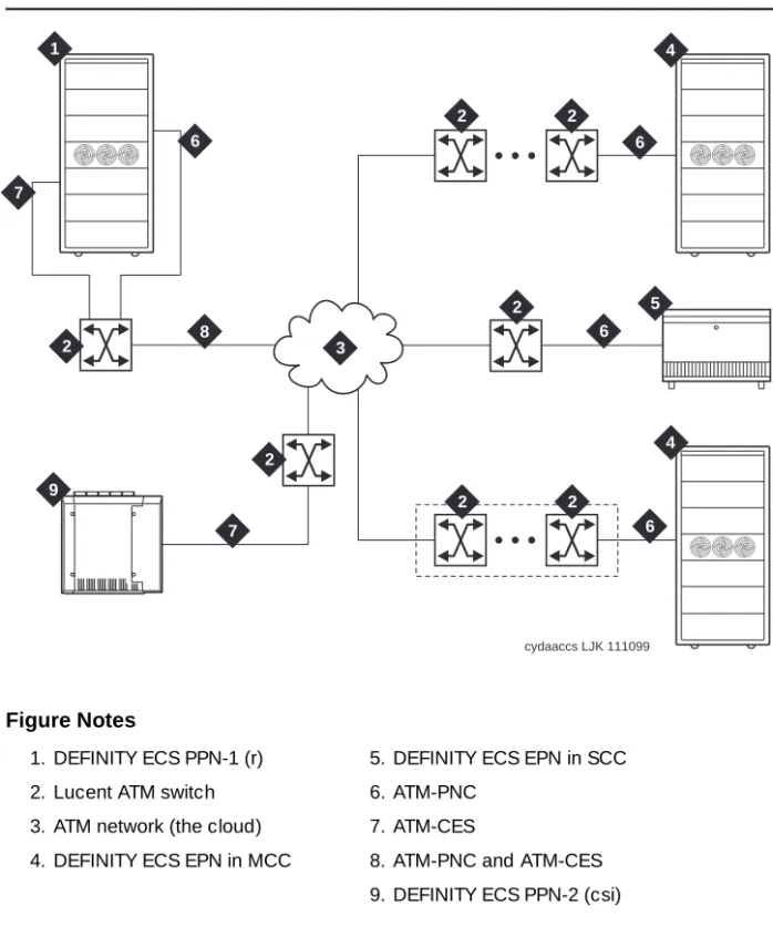
Figure 1-1 shows and example of the basic ATM connections for Release 8r and
Release 8csi system using ATM-PNC and ATM-CES. For more detailed
connection diagrams of the reliability options, refer to ‘‘DEFINITY ECS
configurations’’ on page 1-6.
Figure Notes
Figure 1-1. Example of an ATM-PNC and ATM-CES configuration 1. DEFINITY ECS PPN-1 (r)
2. Lucent ATM switch 3. ATM network (the cloud) 4. DEFINITY ECS EPN in MCC
5. DEFINITY ECS EPN in SCC 6. ATM-PNC
7. ATM-CES
8. ATM-PNC and ATM-CES 9. DEFINITY ECS PPN-2 (csi)
cydaaccs LJK 111099
1
3
4 4
5 6
6 6
6
7
7 8
9 2
2
2 2
2
Required Hardware
Table 1-1 lists the required equipment for standard, high, critical reliability, and
ATM network duplication configurations.
To test the synchronization splitters, you need the following equipment:
■ Phoenix 1541C Test Set with accessory cord kit
■ Phoenix 5575A T1 Test Set with cord kit or equivalent
■ 700A DS1 CPE Loopback Jack1 (comcode 10798867)
■ 103A block
■ 1541CC cable kit
Table 1-1. Minimum required equipment for Release 8 ATM-PNC configurations
Equipment
Reliability level
Standard High
Critical/ATM
Network Duplication
ATM switch 1 1 2
TN2305/TN2306 ATM interface1
for each PN
1. TN2305 (multimode fiber); TN2306 (single-mode fiber) for Release 8 ATM-PNC.
1 12
2. High reliability requires 2 ATM-EI circuit packs in the PPN and 1 ATM-EI in each EPN. 2
T1 or E1 synchronization splitter3
3. The number and uses of the synchronization splitter depend on the configuration and the source(s) from which primary and secondary synchronization is derived. You may need 1 sync splitter per ATM switch. DS1 synchronization requires either no sync splitter or up to a number twice the number of sites.
1 1 1
SC-connected fiber optic cable4
4. Existing fiber optic cable may require an ST-to-SC adapter, depending on the interface at the ATM switch. The TN2305/TN2306 circuit pack requires an SC connector (1 adapter is included in the Fiber Pass-Through Kit).
1 2 (PPN)
1 (each EPN) 2
TN771 maintenance/test circuit
pack5
5. For network duplication; required for systems supporting PRI, BRI, or ASAI. 1
■ RJ45-to-Bantam test cable from the 1541CC cable kit
■ System capacities
Table 1-2 lists the maximum number of TN2305/TN2306 circuit packs allowed in
a DEFINITY ECS.
Table 1-2. Maximum number of ATM interface TN2305/TN2306 circuit packs
Platform
Maximum ATM circuit
packs allowed Description
r 176 2 x 44 port networks (CES) plus 2 in
each PN (PNC)
DEFINITY ECS configurations
Figure 1-2, Figure 1-3, and Figure 1-4 show the ATM-PNC connections for
standard, high, and critical reliability, respectively.
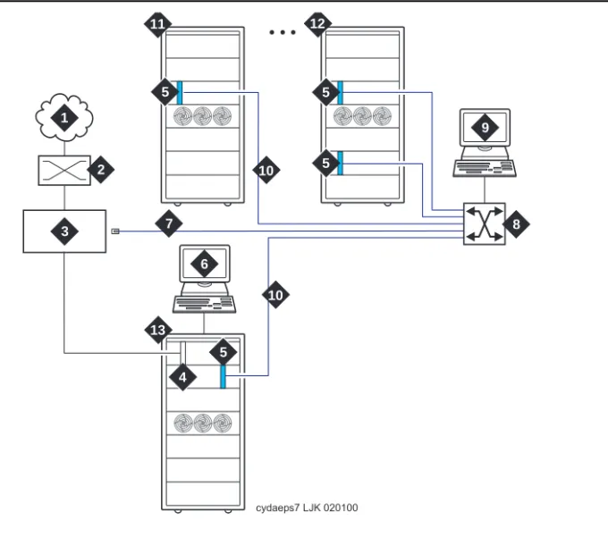
Figure 1-2. ATM-PNC connections for standard reliability Figure Notes
1. Public switched telephone network (PSTN)
2. Main distribution frame (MDF) or smart jack
3. Synchronization splitter.
4. DS1 circuit pack (TN464F)
5. TN2305/TN2306 circuit packs
6. DEFINITY ECS access terminal
7. Timing signal from synchronization splitter through an H600-383 cable to Lucent ATM switch
8. Lucent ATM switch (more than one ATM switch in an ATM-WAN configuration.)
9. ATM switch access terminal
10. Fiber optic cables from ATM OC-3/STM-1 interfaces
11. DEFINITY ECS EPN
12. Split cabinet EPN
13. DEFINITY ECS PPN cydaeps7 LJK 020100
10 10
6 7
11 12
5
5 1
2
3
5 5
4 13
9
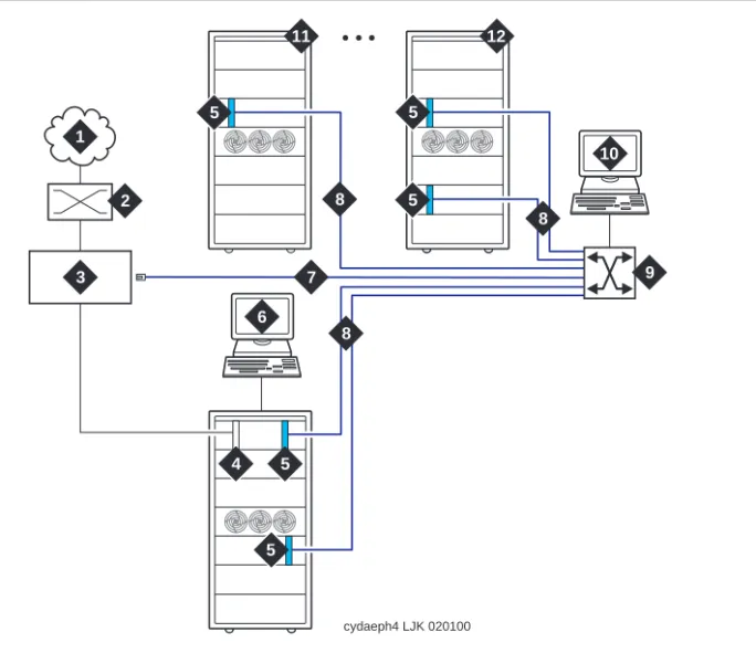
Figure 1-3. ATM-PNC connections for high reliability Figure Notes
1. Public switched telephone network (PSTN)
2. Main distribution frame (MDF) or smart jack
3. Synchronization splitter
4. DS1 circuit pack (TN464F)
5. TN2305/TN2306 circuit packs
6. DEFINITY ECS access terminal
7. Timing signal from synchronization splitter through an H600-383 cable to Lucent ATM switch
8. Fiber optic cables to ATM OC-3/STM-1 interfaces
9. Lucent ATM switch (more than one ATM switch in an ATM-WAN configuration.)
10. ATM switch access terminal
11. DEFINITY ECS EPN
12. Split-cabinet EPN
6 7
8 8
8
11 12
10
cydaeph4 LJK 020100
5 5
5 5
5
4 1
2
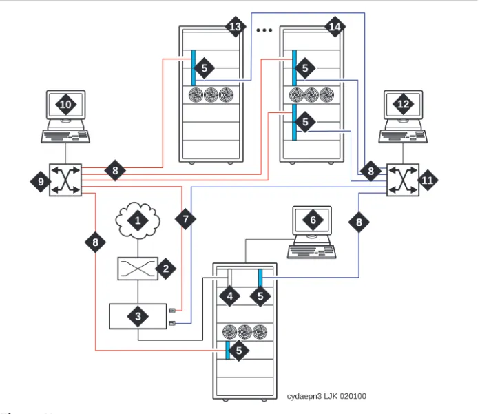
Figure 1-4. ATM-PNC connections for critical reliability or ATM network duplication
Figure Notes
1. Public switched telephone network (PSTN)
2. Main distribution frame (MDF) or smart jack
3. Synchronization splitter
4. DS1 circuit pack (TN464F)
5. TN2305/TN2306 circuit packs
6. DEFINITY ECS access terminal)
7. Timing signal from synchronization splitter through an H600-383 cable to Lucent ATM switch
8. Fiber optic cables to ATM interfaces
9. Lucent ATM switch B
10. ATM switch access terminal B
11. Lucent ATM switch A
12. ATM switch access terminal A
13. DEFINITY ECS EPN
14. Split-cabinet EPN
cydaepn3 LJK 020100
6 7
12
8
8 8 8
8 8 10
13 14
5 5
5
5 5 1
2
4 3
Determine ATM Switch Suitability
To fully support DEFINITY ATM-PNC and provide nonblocking ATM access between all port networks, ATM switches must support at least 400
point-to-multipoint switched virtual connection (SVC) roots or leaves per OC-3/STM-1 interface. Because different switches have different limits—some limit roots, some leaves, and some the total, we have developed the Meiners’ Algorithm to determine whether a switch can support a proposed set of port networks in a proposed switch. This algorithm is available to Lucent engineers as a calculator within a Microsoft Excel spreadsheet. You may access the MS Excel
file at http://info.dr.lucent.com/~meiners/atm.html . Check periodically for
updates.
For best results, use the calculator for one ATM switch at a time. Use trial and error to set the values in the user-defined values section until the feasibility indicator reports YES or PROBABLY.
NOTE:
Use of this spreadsheet is no substitute for thinking. Please apply basic sanity checks to the outcome. ATM switches may have limitations that the calculator does not consider.
To use the calculator, type the network layout and resource limits for the ATM switch you are using. Refer to the following caveats as you input your information:
1. Not all ATM switches have limits on all of the values. If a limit does not apply, enter any very large number (1000000 is good).
2. Some ATM switches (for example, access concentrators) allow a limited ability to configure the limits. Other switches have fixed limits. If you do not know the limits, ask the ATM switch vendor.
3. If your ATM switch is handling non-DEFINITY traffic, enter the resource limits after subtracting the resources used by the non-DEFINITY traffic. 4. If you are using an ATM switch with different limits on different modules or
ports (for example, Lucent Cajun M770):
a. compute the average limits per port to which a DEFINITY port network is attached.
b. select the port with the most restrictive limitations.
c. enter the system limit as these limits times the number of DEFINITY port networks attached to that ATM switch.
NOTE:
The more partitioned the limits are, the less accurate are the results of the spreadsheet.
Figure 1-3 shows an example of a calculation.
PROBABLY means that this application is okay under any reasonable loads. Check the constraint tests results to see what kind of loads might be a problem.
YES means that this application is okay under any load.
NO means that this application is not reasonable. See the Constraint Tests results to see what resource you are short of. See if you can increase this resource, or decrease the number of port networks.
Table 1-3. Sample calculation
Network Layout
Customer SV
ATM switch AC120
Total number of DEFINITY port networks: 25
Number of PNs directly attached directly to this ATM switch: 12
Is the DEFINITY PPN directly attached to this ATM switch (yes/no)
yes
Number of trunks on this ATM switch (inter-ATM-switch connections)
1
Any transit traffic through this ATM switch (yes/no) no
Aggregate peak phone calls rate per hour in all directly connected PNs
10000
Bidirectional aggregate trunk bandwidth in Mbps 155.52
Application bandwidth in kbps needed per port network 128
ATM Switch Resource Limits (see "Limits" sheet for help)
Number of PP SVCs supported: 1000
Number of PMP (roots) supported: 6250
Number of PMP parties (leaves) supported: 8334
Number of PMP endpoints (roots+leaves) supported: 1000000
Total number of SVCs (PP+PMP) supported 1000000
Per-port SVC limit (normally based on VCI range) 1000000
Setups per second at <220 ms per setup 1000000
Feasibility PROBABLY
UNKNOWN means that special engineering is required for this application because of the transit traffic. The special treatment is necessary because the feasibility depends on the volume of the transit traffic. Making any of the changes suggested for NO above might make it feasible regardless of the transit traffic.
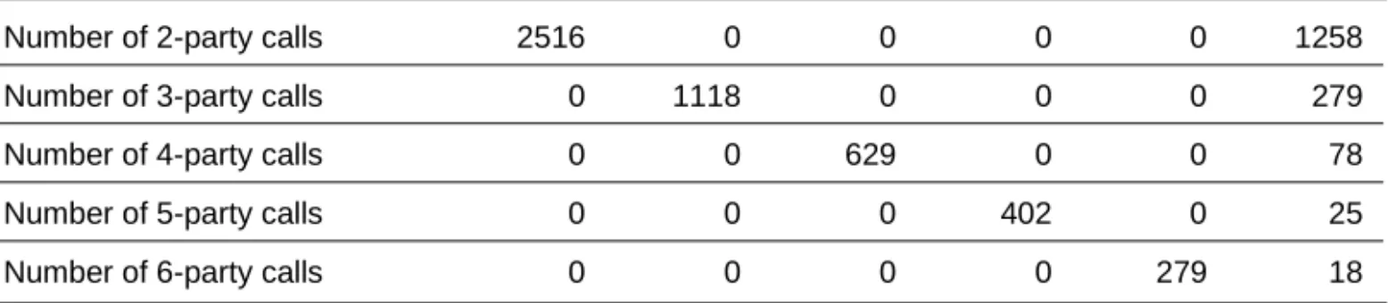
Constraint tests
If your calculations do not yield a YES, this section provides the resources of which you are short. These tests check 7 ATM switch resource limitations against
6 different application scenarios. A 1 in the Test Results (Table 1-7) indicates a
passed test; a 0 indicates a failed test. To achieve a YES feasibility, all 42 tests must pass. To achieve a PROBABLY, only 21 tests (indicated in bold) must pass.
Table 1-4. Constants
Timeslots per port network 500
Cache hit ratio 50%
EAL+PACL bandwidth 96
Table 1-5. Computed values
Number of nonlocal port networks 13
Effective number of port networks for PP 24
Effective number of port networks for PMP 24
Number of available timeslots 10064
Per-port SVCs (PP+PMP) needed 572
PP SVCs perPN 3
Total PP SVCs 72
PP cells per second required over trunks 15158
Aggregate cells per second available over trunks 366792
Bandwidth-limited maximum phone calls over trunks 2032
Final notes
The goal is to engineer the network so that in all reasonable applications, you always run out of DEFINITY time slots before running out of ATM switch resources. This is required to provide acceptable service to the customer.
These calculations factor in phone calls only. There is no specific
accommodation for the ATM SVC cache, or for special features such as music, announcements, and group paging. The theory behind using 500 as the number of timeslots in a port network rather than the real number (484) is to allow for a normal amount of these special features. If you use multiple music on hold, group paging, and so forth, you may need special engineering.
This calculator determines that an application is PROBABLY feasible if it can
handle reasonable activity mixes. The three columns in Table 1-7 that have bold
entries define what is meant by reasonable. These tests require that the switch be able to handle a complete suite of 2-party calls, a complete suite of 3-party calls, and a mixed suite that involves some calls of each type. For best results, your application should pass all the constraint tests.
Any ATM switch that processes transit traffic (that is, connections that do not either originate or terminate on any of the port networks directly attached to it) may require special engineering. This is possible if the number of trunks on the Table 1-6. Application scenarios
Number of 2-party calls 2516 0 0 0 0 1258
Number of 3-party calls 0 1118 0 0 0 279
Number of 4-party calls 0 0 629 0 0 78
Number of 5-party calls 0 0 0 402 0 25
Number of 6-party calls 0 0 0 0 279 18
Table 1-7. Test results
Constraint 1: Timeslots 1 1 1 1 1 1
Constraint 2: PMP roots 1 1 1 1 1 1
Constraint 3: PP 1 1 1 1 1 1
Constraint 4: PMP leaves 1 1 1 1 0 1
Constraint 5: PMP endpoints 1 1 1 1 1 1
Constraint 6: Total SVCs 1 1 1 1 1 1
Constraint 7: Per-port SVCs 1 1 1 1 1 1
Constraint 8:Performance 1 1 1 1 1 1
ATM switch is more than one. If this is the case, the calculator first attempts to determine if the application is feasible despite the transit traffic. If it is, it reports the feasibility as YES or PROBABLY. If not, it reports the feasibility as
UNKNOWN, requiring special engineering.
Known limits of commonly used ATM switches
Use the limits shown in Table 1-8 to do your own calculations. To make it easier
as you use the calculator, we suggest that you
1. Select and copy the values from the table in the spreadsheet. 2. Select the values on the sample calculation.
3. Select Edit > Paste Special with the transpose option to paste the values into the calculator.
NOTE:
A limit shown as 1000000 means that this ATM switch has no independently defined limit on this resource.
Schedule Installation or Upgrade
Schedule the installation or upgrade with the Lucent Technologies Technical Support Organization (TSO) and NetCare® Professional Services (NPS). See
‘‘Where To Call for Technical Support’’ on page -xi.
Table 1-8. Known limits of commonly used ATM switches
Switch
Number of PP SVCs supported
Number of PMP (roots) supported
Number of PMP parties (leaves) supported
Number of PMP endpoints (roots + leaves) supported
Total number of SVCs (PP+PMP) supported
Per-port SVC limit (normally based on VCI range)
Setups/s at <220 s/set up Lucent PSAX1250
Release 5.0 1000000 1000000 1000000 1000 1000000 1000000 1000000
Release 5.1 1000000 1000000 1000000 4000 1000000 1000000 1000000
Release 6 (with recommended admin)
1000 6250 8334 1000000 1000000 1000000 1000000
Lucent M770 r2
Dual Domain Modules 1&8
1000000 4096 1000000 1000000 1000000 1000000 1000000
Dual Domain Modules 2-7&9-14
1000000 2048 1000000 1000000 1000000 1000000 1000000
Single Domain 1000000 1024 1000000 1000000 1000000 1000000 1000000
Fore ASX1000
Release 6 (with memory model 5)
2
Installing a DEFINITY ECS
ATM-CES
This chapter describes the procedures for installing a new DEFINITY ECS Release 8 ATM-CES The procedure is simple in that you install the DEFINITY ECS then install the ATM switch and the TN2305/TN2306 interface circuit packs.
Making it an ATM-CES is done administratively (refer to Chapter 5, ‘‘Administering
ATM-PNC and ATM-CES’’).
NOTE:
ATM-CES works only with TN2305/TN2306 ATM interface circuit packs.
Equipment Installation
To prepare for a new DEFINITY ECS ATM-CES installation, you need to install the DEFINITY ECS first. For instructions on installing DEFINITY ECS, refer to the following installation books:
■ DEFINITY Enterprise Communications Server Release 8 Installation and
Test for Multicarrier Cabinets
■ DEFINITY Enterprise Communications Server Release 8 Installation and
Test for Single-Carrier Cabinets
■ DEFINITY Enterprise Communications Server Release 8 Installation,
Upgrades, and Additions for Compact Modular Cabinets
Review the reliability configurations for DEFINITY Release 8 ATM (refer to Figure
1-2 through Figure 1-4).
Follow the steps in Table 2-1 to ensure that
■ the applicable equipment is installed correctly.
■ the customer’s configuration is properly recorded (use worksheet in
Appendix A, ‘‘Baselining the Customer’s Configuration’’).
Table 2-1. General installation process
√ Step Action Description
1. Install DEFINITY ECS Refer to the appropriate installation book for your platform
See ‘‘DEFINITY ECS configurations’’ on page 1-6 for
connection schematics. 2. Install ATM switch(es)
or access concentrators
Refer to your ATM switch’s quick reference guide.
3. Install ATM interface circuit pack
Insert the TN2305/TN2306 circuit pack(s) into the appropriate slot(s).
4. Route the fiber optic cables between the ATM switch and the DEFINITY PPN and EPNs.
Follow the fiber pass-through procedure in the appropriate DEFINITY ECS installation book.
!
WARNING:
Be sure that the fiber optic cable is secured so that the door of the DEFINITY ECS switch does not pinch or bend the cable.
For csi platform, see Figure 2-1 for a diagram of the NAA7 board that routes fiber optic cabling from the back of the switch to the front.
5. Connect the fiber optic cables
Connect the fiber optic cables to the ATM switch.
NOTE:
If the installation uses the customer’s existing fiber, you may need an ST-to-SC adapter (1 included in Fiber Pass-Through Kit).
6. Connect the fiber optic cables to the ATM interface circuit packs
Connect fiber optic cable to the SC connector on the faceplate of each TN2305/TN2306 circuit pack in the DEFINITY PPN and EPN.
■ The TN2305/TN2306 circuit pack interface requires SC connectors (see Note in Step 5).
■ Do not reuse existing fiber cabling with ST connectors
at both the DEFINITY ECS and the ATM switch. This requires an ST-to-SC adapter at both ends. It is better to order the cable with the SC connectors at both ends.
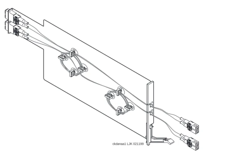
NAA7 Board (csi/c models only)
The NAA7 board routes fiber optic connections from the rear of the cabinet
through the front faceplate as shown in Figure 2-1. The SC fiber connectors that
go through the faceplate connect to the faceplate connectors on the TN2305/TN2306 ATM circuit pack.
Figure 2-1. NAA7 board (csi and c models only)
7. Record configuration Record DEFINITY ECS switch-to-ATM port (port locations for each ATM circuit pack) in Table A-1 in Appendix A,
‘‘Baselining the Customer’s Configuration’’.
8. Record fiber connections
Record the fiber optic cable runs on the lightwave interface (LIU) diagram (Figure A-1 in Appendix A, ‘‘Baselining
the Customer’s Configuration’’).
Table 2-1. General installation process
√ Step Action Description
Continued on next page
A
B
A
B
ckdanaa1 LJK 021199
A B
A
B
A
3
Installing a DEFINITY ECS
ATM-PNC
This chapter describes the procedures for installing a new DEFINITY ECS Release 8 ATM system. The process includes
■ Equipment Installation
■ Synchronization Installation and Testing
■ ATM Network Duplication
Equipment Installation
If the ATM switch and interface circuit packs are already installed, then the actual
upgrade to ATM-PNC is done administratively in Chapter 5, ‘‘Administering
ATM-PNC and ATM-CES’’.
To prepare for a new DEFINITY ECS ATM installation refer to the following books:
■ DEFINITY Enterprise Communications Server Release 8 Installation and
Test for Multicarrier Cabinets
■ DEFINITY Enterprise Communications Server Release 8 Installation and
Test for Single-Carrier Cabinets
Review the reliability configurations for DEFINITY Release 8 ATM (refer to Figure
1-2 through Figure 1-4) and determine the synchronization sources (DS1, E1, or
Slot restrictions for an ATM interface circuit packs are similar to expansion interface circuit packs:
■ PPN: ATM interface circuit packs used for ATM-PNC must occupy the slots
labeled EXPANSION INTERFACE.
■ EPNs: ATM interface circuit packs used for ATM-PNC can occupy slot 1
(and 2 if duplicated) on carrier A, and slot 2 (and 3 if duplicated) on carrier B
Follow the steps in Table 3-1 to ensure that
■ the applicable equipment is installed correctly.
■ the customer’s configuration is properly recorded (use worksheet in
Appendix A, ‘‘Baselining the Customer’s Configuration’’).
Table 3-1. General installation process
√ Step Action Description
1. Install DEFINITY ECS switch
Refer to the appropriate installation book
See ‘‘DEFINITY ECS configurations’’ on page 1-6 for connection schematics.
2. Install ATM switch(es) or access
concentrators
Refer to your ATM switch’s quick reference guide.
3. Check the distances from the ATM switch to the DS1 timing source
Use the information in Table 3-3 to determine the
maximum cable run lengths for the configuration for more information.
4. Install ATM interface circuit pack
Insert the TN2305/TN2306 circuit pack(s) into the appropriate slot(s).
5. Route the fiber optic cables between the ATM switch and the DEFINITY PPN and EPNs.
Follow the fiber pass-through procedure in the appropriate installation book.
!
WARNING:
Be sure that the fiber optic cable is secured so that the door of the DEFINITY ECS switch does not pinch or bend the cable.
6. Connect the fiber optic cables
Connect the fiber optic cables to the ATM switch.
NOTE:
If the installation uses the customer’s existing fiber, you may need an ST-to-SC adapter (1 included in Fiber Pass-Through Kit).
Synchronization Installation and
Testing
A DEFINITY ATM-PNC requires network synchronization for DS1 circuit packs not to slip relative to the LEC/IXC switches. The ATM switch serves as the sync reference source for the DEFINITY. The ATM switch, in turn, derives primary and secondary sync. To accomplish this, the most common option is to use
synchronization expanders (splitters). 7. Connect the fiber
optic cables to the ATM interface circuit packs
Connect fiber optic cable to the SC connector on the faceplate of each TN2305/TN2306 circuit pack in the DEFINITY PPN and EPN.
■ The TN2305/TN2306 circuit pack interface requires SC connectors (see Note in Step 5).
■ Do not reuse existing fiber cabling with ST connectors
at both the DEFINITY switch and the ATM switch. This requires an ST-to-SC adapter at both ends. It is better to order the cable with the SC connectors at both ends.
8. Record configuration Record DEFINITY ECS switch-to-ATM port (port locations for each ATM circuit pack) in Table A-1 (in Appendix A, ‘‘Baselining the Customer’s Configuration’’).
NOTE:
Read the MAC addresses from the ATM switch (refer to your ATM switch’s quick reference guide) and record them in Table A-1.
9. Record fiber connections
Record the fiber optic cable runs on the lightwave interface (LIU) diagram (Figure A-1) in Appendix A, ‘‘Baselining the Customer’s Configuration’’.
10. Install and test synchronization splitter, if required.
Follow the procedures for installing and testing the synchronization splitter and the T1 or E1 timing source in
‘‘Synchronization Installation and Testing’’ on page 3-3.
Table 3-1. General installation process
√ Step Action Description
Connections without synchronization splitters
In some configurations the ATM switches are traced to network clocks through their SONET/SDH interfaces, not requiring any synchronization splitters. However, the ATM switch could require a single splitter if only one of the sync sources is derived from the network.
The ATM switches may obtain their network synchronization as follows:
■ The ATM switch gets its network timing reference from its
SONET/SDH/SDIT interface to that network.
■ Or if the customer wants to use a DS1 source for network synchronization
that also happens to be a DEFINITY ECS switch trunk, then one sync splitter is necessary to send a copy of that DS1 signal to the ATM switch. The DS1 circuit pack is only an indirect timing reference for the DEFINITY ECS switch.
Connections needing synchronization splitters
If the ATM network does not provide a synchronization expander (splitter), then the ATM configurations may require one that takes a DS1 T1 or E1 signal and redirects it to the
■ ATM switch(es), depending on configuration and duplication
■ DEFINITY ECS through the DS1 circuit pack
This creates a single synchronization source.
Check the customer’s configuration carefully so that you can
■ Connect the hardware correctly during installation
■ Properly administer the synchronization plan later (Chapter 5,
‘‘Administering ATM-PNC and ATM-CES’’)
This section covers the synchronization installation and test process.
■ Splitter descriptions—Describes the splitter’s inputs and outputs
■ Synchronization splitter connections—Connection diagrams for timing
connections through a DSU/CSU (Figure 3-6) and an ICSU (Figure 3-7)
■ Verify the DS1 service—Checks for presence of the DS1 T1 or E1 timing
source and the general health of the DS1 circuit pack.
■ Installing and testing the splitter provides the following information
— Splitter port tests (401A/401A only)
— Installing a 400A T1 splitter
Installing and testing the synchronization splitter involves interrupting the DS1 signal provided by the service provider. Even though the DS1 circuit pack should be down less than 5 minutes, before removing a working T1/E1 span, contact the service provider. Failure to notify the T1/E1 service provider may result in:
— The service provider looping the T1/E1 span back to the subscriber.
— A span alarm being detected at the central office and the span being taken out of service, sending an AIS (blue Alarm) to the DEFINITY ECS. The synchronization signal is necessary for testing equipment and connections.
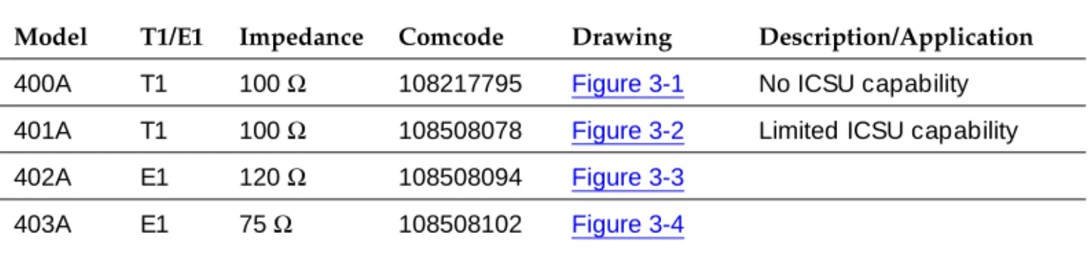
Splitter descriptions
Table 3-2 describes the 4 splitter models and their capabilities. The drawings
show the splitters and their connection points. Figure 3-5 shows a schematic of
the 2 jumper sets and their connections for 401A, 402A, and 403A sync splitters.
Table 3-2. Synchronization splitter models and attributes
Model T1/E1 Impedance Comcode Drawing Description/Application
400A T1 100 Ω 108217795 Figure 3-1 No ICSU capability
401A T1 100 Ω 108508078 Figure 3-2 Limited ICSU capability
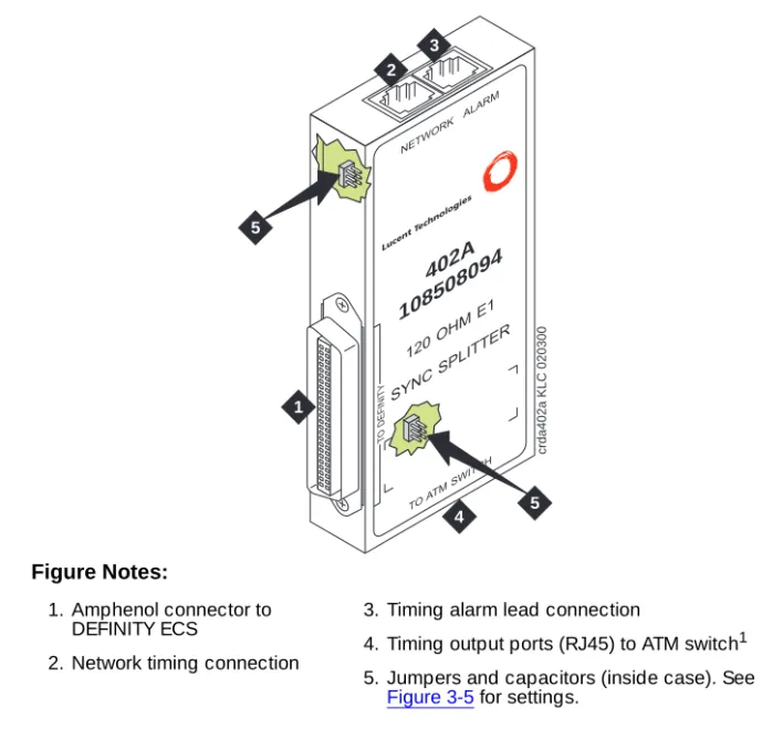
402A E1 120 Ω 108508094 Figure 3-3
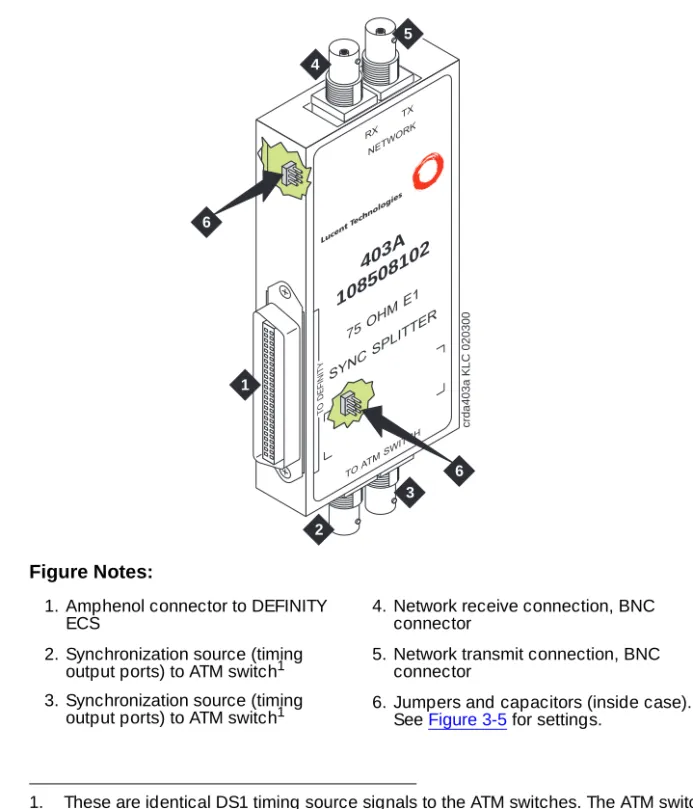
403A E1 75 Ω 108508102 Figure 3-4
Figure 3-1. 400A synchronization splitter Figure Notes:
1. From network interface 2. Amphenol connection to
DEFINITY ECS
3. Timing output port (J1) to the ATM switch1 4. Timing output port (J2) to the ATM switch1
1. Ports J1 and J2 provide identical DS1 timing source signals to the ATM switches. The ATM switch can use two separate DS1 timing signals (one at a time from two separate spans).
J1 J2
crda400a LJK 071698
1
2 3
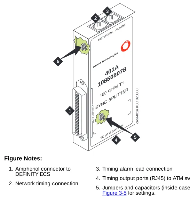
Figure 3-2. 401A synchronization splitter Figure Notes:
1. Amphenol connector to DEFINITY ECS
2. Network timing connection
3. Timing alarm lead connection
4. Timing output ports (RJ45) to ATM switch1 5. Jumpers and capacitors (inside case). See
Figure 3-5 for settings.
1. Ports J1 and J2 provide identical DS1 timing source signals to the ATM switches. The ATM switch can use two separate DS1 timing signals (one at a time from two separate spans).
401A
108508078
100OH
MT1
SYNC
SPLIT
TER
TOAT MSWITCH NETWORK
ALARM
Luce ntTe
chno logie
s
crda401a KLC 020300
1
2 3
4
T
O
DEFINITY
5
Figure 3-3. 402A synchronization splitter Figure Notes:
1. Amphenol connector to DEFINITY ECS
2. Network timing connection
3. Timing alarm lead connection
4. Timing output ports (RJ45) to ATM switch1 5. Jumpers and capacitors (inside case). See
Figure 3-5 for settings.
1. Ports J1 and J2 provide identical DS1 timing source signals to the ATM switches. The ATM switch can use two separate DS1 timing signals (one at a time from two separate spans).
402A
108508094
120OH
ME1
SYNC
SPLIT
TER
TOAT MSWITCH NETWORK
ALARM
Luce ntTe
chno logie
s
crda402a KLC 020300
1
2 3
4
T
O
DEFINITY
5
Figure 3-4. 403A synchronization splitter Figure Notes:
1. Amphenol connector to DEFINITY ECS
2. Synchronization source (timing output ports) to ATM switch1 3. Synchronization source (timing
output ports) to ATM switch1
1. These are identical DS1 timing source signals to the ATM switches. The ATM switch can use two separate DS1 timing signals (one at a time from two separate spans).
4. Network receive connection, BNC connector
5. Network transmit connection, BNC connector
6. Jumpers and capacitors (inside case). See Figure 3-5 for settings.
403A
108508102
75OHM
E1
SYNC
SPLITTER
TOAT MSW
ITCH RX
TX
Lucent Technologies
NETW ORK
T
O
DEFINITY
2
3 4
5
6
6
crda403a KLC 020300
Figure 3-5. Jumper settings (401A/402A/403A) Figure Notes:
1. Amphenol connection to DEFINITY ECS switch
2. Row of capacitors
3. Jumpers for incoming network connections
4. Incoming network transmit and receive connections
5. Jumper 1-2 = true ground Jumper 5-6 = shield grounded Jumper 3 = TX cable ground Jumper 4 = RX cable ground Default connections = 1-2, 3-5
6. True ground
7. Cable shield grounded 8. Jumper 1-2 = true ground
Jumper 5-6 = shield grounded
Jumper 3 = ATM switch A TX cable ground Jumper 4 = ATM switch B TX cable ground Default connections = 3-5, 4-6
9. Output jumpers
10. Timing output to ATM switch A 11. Timing output to ATM switch B
1
2
8
7
2 1 4 3 6 5
TX TX
5
jpda40xa KLC 020300
402A
108508094
120 OHM E1
SYNC SPLITTER
TO ATM SWITCH
TO
DEFINITY
NETWORK ALARM
3
6
2 1 4 3 6 5
TX RX
Synchronization splitter connections
The splitter connects to a timing source. Figure 3-6 shows the synchronization
connections through a DSU/CSU (400A), and Figure 3-7 shows the
synchronization connections through an ICSU (400A). Figure 3-8 shows the
synchronization connections directly to the timing source (401A, 402A, 403A).
Figure 3-6. Synchronization connections through an external DSU/CSU (400A)
Figure Notes:
1. Public Switched Telephone Network (PSTN)
2. Main distribution frame (MDF) or smart jack.
3. Channel service unit (CSU)
4. H600-307-GR2 cable
5. 400A T1 (100 Ω) splitter connects to the DEFINITY ECS
6. H600-383 quad cable from sync splitter to ATM switch A
7. H600-383 quad cable from sync splitter to ATM switch B (critical reliability/ATM network duplication)
8. Lucent ATM switch A
9. Lucent ATM switch B (critical reliability/ATM network duplication)
cydaatm2 LJK 020100
1
3
4
5 6 7 2
Use the information in Table 3-3 to determine the maximum cable run lengths for the configuration.
Figure 3-7. Synchronization connections through an ICSU (400A) Figure Notes:
1. Public Switched Telephone Network (PSTN)
2. Main Distribution Frame (MDF) or smart jack
3. H600-383 quad cable
4. 400A T1 (100 Ω) splitter connected to DEFINITY ECS
5. H600-383 quad cable from sync splitter to ATM switch A
6. H600-383 quad cable from sync splitter to duplicated ATM switch B (critical reliability)
7. Lucent ATM switch A
8. Lucent ATM switch B (critical reliability/ATM network duplication)
9. ICSU
cydaatm1 LJK 020100
1
2 3
5 6
4 9
Figure 3-8. Synchronization connections directly to timing source (401A/402A/403A)
Figure Notes:
1. Public switched telephone network (PSTN)
2. Main distribution frame (MDF) or smart jack
3. H600-383 quad cable
4. 401A T1 (100 Ω) splitter, 402A E1 (120 Ω) splitter, or 403A E1 (75 Ω) splitter connected to DEFINITY ECS
5. H600-383 quad cable from sync splitter to ATM switch A
6. H600-383 quad cable from sync splitter to duplicated ATM switch B (critical reliability/ATM network duplication)
7. Lucent ATM switch A
8. Lucent ATM switch B (critical reliability/ATM network duplication)
cydaatm3 KLC 020200
5 6 3
7 8
4 1
Use the information in Table 3-3 to determine the maximum cable run lengths for the configuration.
Table 3-3. Maximum cable lengths
Splitter Used in Cable Maximum distance from splitter to ATM switch
400A T1 100 Ω
North America (USA and Canada)
H600-3831 shielded twisted pair
1. Must have RJ45 connectors on each end.
250 feet 76 meters
401A T1 100 Ω
North America (USA and Canada)
H600-3831 shielded twisted pair
1310 feet2 393 meters
402A E1 120 Ω
See Table 3-4 120-Ω
shielded twisted pair
1000 feet2 305 meters
2. The loss allowed in the cable is 6 dB. Typical cables have losses of 0.6 dB/100 ft; hence, 1000 feet may be considered a typical distance. Distance varies if cables with different losses are used.
403A E1 75 Ω
See Table 3-4 75-Ω
coaxial
1000 feet2 305 meters
Table 3-4 lists the splitter model(s) applicable to specific countries.
Table 3-4. Country-specific splitter applications
Country
Splitter model
400A/401A T1 100 Ω
402A E1 120 Ω
403A E1 75 Ω
Argentina Y
Australia Y
Austria Y Y
Bahrain Y Y
Belgium Y Y
Brazil Y
Canada Y
China Y
Columbia Y
Denmark Y Y
Egypt Y Y
Finland Y Y
France Y Y
Germany Y Y
Hong Kong Y
India Y Y
Indonesia Y Y
Ireland Y Y
Italy Y Y
Japan1
Korea Y Y
Luxembourg Y Y
Malaysia Y Y
Mexico Y
Netherlands Y Y
New Zealand Y Y
Norway Y Y
Philippines Y Y
Poland Y Y
Portugal Y Y
Russia Y Y
Saudi Arabia Y Y
Singapore Y
South Africa Y Y
Spain Y Y
Sri Lanka Y Y
Sweden Y Y
Switzerland Y Y
Taiwan Y Y
Ukraine Y Y
UAE Y Y
UK Y Y
USA Y
Uzbekistan Y Y
Vietnam Y Y
1. Japan uses both 75-Ω and 120-Ω T1; 402A and 403A sync splitters will also work with T1s.
Table 3-4. Country-specific splitter applications —
Continued
Country
Splitter model
400A/401A T1 100 Ω
402A E1 120 Ω
403A E1 75 Ω
Verify the DS1 service
To verify the DS1 service, use the procedure in Table 3-5. Have the ATM switch
installer verify the synchronization source.
Table 3-5. T1 or E1 service verification procedure
√ Step Action Command Description
1. Check timing signal
Check that the GREEN STATUS 3 LED on the designated DS1 circuit pack is on steady.
2. Test the DS1 circuit pack
test board UUCSS
Test the designated DS1 board.
If any one of Test 138 through 145 fails, follow the repair procedures listed in DEFINITY ECS Maintenance for R8r.
3. Run error report list
measurements ds1 UUCSS summary
Verify that the report is free of errors.
See Table 3-6 to help interpret the report.
4. Identify active synchronization source
status synchronization
Verify that the designated DS1 circuit pack is the active sync source.
Note: The DS1circuit pack is not the sync source; it simply shows where the sync splitter is connected.
Table 3-6. Interpretation of the list measurements report
Displayed
Field Function Indication
Test: cpe-loopbac k-jack
3-in-24 stress test pattern
The loopback jack test is active
Synchronize d
= Y
= N
The DS1 circuit pack is synchronized to the looped 3-in-24 pattern and is counting the bit errors detected in the pattern until the test is ended.
Retry the test:
1. Stop the test (test ds1-loop UUCSS end
cpe-loopback-jack-test).
2. Restart the test (test ds1-loop UUCSS cpe-loopback-jack-test-begin)
3. Repeat Steps 1 and 2 a maximum of 5 times, as necessary.
If the circuit pack never synchronizes, it is possibly due to intermittent connections or a broken wire in a receive or transmit wire pair.
Bit Error Count
Cumulative detected errors
0 indicates that there are no wiring problems. A count that sits at 65535 or continues to increment by several hundred to several thousand errors with each subsequent list measurements command indicates
■ Intermittent or corroded connections
■ Severe crosstalk
■ Impedance imbalances between the two
conductors of the receive or the transmit pairs. 1. Replace wiring, if necessary.
2. Note whether the Extended Super Frame (ESF) error and performance counters summaries (errored seconds, bursty errored seconds, and so forth) also increment. Although these counters are not used with the loopback jack test, they do increment as errors occur.
Installing and testing the splitter
The splitter must be installed and tested before the upgrade and cutover. The purpose of testing the splitter is to
■ Prove that there is enough signal level for the cable length to the ATM
switch:
— up to 130 ft. (39.65 m) for 400A
— within the standard 6 dB allowable loss for 401A, 402A, and 403A
(see Table 3-3)
■ Ensure that the DS1 circuit pack functions properly while receiving the
DS1 signal level output from the splitter (Ports J1 and J2 unterminated).
Table 3-7 shows the configurations of the test cable and ports on the sync
splitter.
Splitter port tests (401A/401A only)
NOTE:
The standard RJ45-to-Bantam test cable does not work with the 403A.
To test the splitter ports J1 or J2, use the procedures in Table 3-8, using the RJ45
to Bantam Test cable from the 1541CC cable kit.