Design & Analysis of Six Port Technology for
Multi input Multi output and Millimeter
wave Radio Receiver Applications
SK. Masthanbasha1, Dr. Habibullakhan2
Research Scholar, Dept. of ECE, Acharya Nagarjuna University, Guntur, AP, India1
Dean (Student affairs), Dept. of ECE, K.L. University, Vijayawada, AP, India 2
ABSTRACT: With recent advances in semiconductor processing technology and the development of reconfigurable devices, high bit-rate software-defined radio (SDR) has become practical for commercial applications. This paper proposes an SDR receiver platform based on a new substrate integrated waveguide six-port structure. This SDR receiver platform operates from 22 to 26 GHz and it is designed to be robust, low cost, and suitable for different communication schemes. In this study, the receiver is demonstrated to support quadrature phase-shift keying and 16 quadrature amplitude modulation schemes. System-level sim- ulation is made and prototype circuits are fabricated to evaluate the system performance. It is found that the combination of SDR and six-port technology can provide a great flexibility in system configuration, a significant reduction in system development cost, and also a high potential for software reuse. The proposed receiver shows a possible application of universal direct demodulator for future SDR terminals in various wireless communication systems.
KEYWORDS: Digital receiver, quadrature amplitude phase- shift keying (QPSK), six-port junction, 16 quadrature amplitude modulation (QAM16), software-defined radio (SDR), substrate integrated waveguide (SIW).
I. INTRODUCTION
SOFTWARE-DEFINED radio (SDR) is an information transfer system (ITS) that combines technologies from the historically separated fields of computers and radios. Emerging from military applications, SDR has gained much attention among researchers and practitioners working in the wireless communication field and it
has been identified as one potential method to enhance the flexibility and usability of Wireless communication systems.
In the past, the limited operating speed of analog-to-digital converter (ADC) and limited processing ability of reconfig- urable chips for digital signal processing were known to slow down the development of SDR towards useful commercial ap- plications. With recent advances in semiconductor processing technology and the development of reconfigurable devices such as digital signal processors (DSPs) and field-programmable gate arrays (FPGAs), SDR has now become practical in system solutions including wireless local area networks (LANs), audio, television broadcasting, and interoperability between different radio services.
The block diagram of a typical practical SDR receiver is shown in Fig. 1. The RF signals are first down-converted, then such down-converted signals are digitized and sent to the DSP, and all of the subsequent processing is implemented in software. SDR consists of adaptable hardware components coexisting with software modules that govern the hardware behavior. Depending upon a specific application, SDRs may lso need to perform source and channel coding/decoding, multiple-access processing, frequency spreading/de-spreading, and encryption/decryption. While these basic functions are the same for SDRs and traditional radios, the implementation of these functions may be very different.
The primary distinction between SDRs and traditional radios lies in the programmability or configurability of SDRs, whereas traditional radios either do not have or have a limited capability in this respect. With SDR, software functions define the base- band and protocol elements and provide an environment for easy application development. Without introducing new hard- ware, an SDR can change operating characteristics or param- eters such as the operating frequency range, modulation type, bandwidth, maximum radiated or conducted output power, and network protocols by changing the software programs executing in processing resources. This enables a single wireless device to be reprogrammed for using different modulation, coding, and access protocols. [1]–[5]
This great flexibility of SDR provides a tremendous oppor- tunity for solving interoperability problems between the many different existing standards, implementing new standards, and minimizing the amount of hardware necessary to perform re- quired communications across these different standards. SDR also allows more efficient use of the spectrum by facilitating spectrum sharing and allowing equipment to be reprogrammed to more efficient modulation types. Its capability of being pro- grammed also enhances interoperability between different radio services.
II. PLATFORM ARCHITECTURE
One key point of SDR is to have a digital-processing kernel with almost infinite processing ability. Although DSP and semiconductor technology have been developed rapidly over the past ten years, the operating speed level of the current DSP chip cannot completely support a multichannel multimodu- lation SDR at the IF level. Therefore, certain software radio systems adopt multichip architecture and parallel algorithm, thereby increasing the design complexity and potential cost. Instead of digitalizing signals at IF, signals can also be digital- ized at baseband to reduce the processing requirement for DSP chips. As a new solution of SDR design, the direct demodu- lator architecture, based on six-port technology, or “multiport demodulator,” is used in our proposed RF software receiver. Signals are down-converted from RF to baseband directly by a six-port junction.
Six-port technology has been under development for the past 30 years starting with microwave and millimeter-wave mea- surement and network analyzer applications. The vector ratio of incident waves at two input ports can be calculated using the output power readings at the remaining four ports. In doing this, there is no need of down-converting the signal to IF to make phase comparison. In 1994, the first six-port receiver was proposed as a direct digital receiver [6]. In principle, the six- port consists of linear circuits with signal dividers and com- biners (or couplers) interconnected in such a way that four or “ ” different vectorial combinations of the reference signal and signal to be measured (receiver signal) are obtained. The uses of different phase shifts and attenuation between the compo- nents such that the two RF input signals generate different am- plitudes and phases at four output ports. The signal levels of the four baseband output signals are detected using Schottky diode detectors or other RF quadratic detectors. By applying suitable baseband signal-processing algorithms, the magnitude and phase of the unknown received signal can be determined from the four output signal levels for the given modulation and coding scheme [6].
Fig. 2. Architecture of six-port software receiver.
a set of BPFs and baseband amplifiers. The DSP section is responsible for the baseband signal processing such as demod- ulation and decoding. The receiver is designed to operate at the millimeter-wave frequency and operates over a wideband for multimode schemes.
As shown in previous research, the six-port receiver approach offers wideband accommodation to ever-changing communi- cation specifications required in SDR systems. Some six-ports can offer impressive widebands, namely, 2–2200 MHz [7],
0.5–9 GHz [8], and 22–31 GHz [9]. Therefore, the six-port re- ceiver can be used in various applications such as FM radio, TV, cordless phones, paging, global positioning systems (GPSs), digital audio broadcasting (DAB), mobile satellite (MSAT), personal communications systems (PCSs), radar satellite, satellite multimedia, local multipoint communication systems (LMCSs), and so on. Compared with the traditional SDR receiver system, the six-port direct SDR receiver has wider bandwidth, low cost for RF circuits, and low DSP capability requirement.
III. SIW SIX-PORT CIRCUIT DESIGN
As a key RF component of the proposed receiver, an SIW six-port circuit [10] was designed for the proposed SDR receiver platform. The SIW technology, as a part of the substrate inte- grated circuits (SICs) family, has been proposed recently [11], [12] as an attractive technology for low-loss, low-cost and high- density integration of microwave and millimeter-wave compo- nents and subsystem. It is appropriate for the design of the six- port receiver and radar.
The SIW is a type of rectangular dielectric-filled waveguide that is synthesized in planar substrate with arrays of metallic vias to realize bilateral edge walls, and its transitions with planar structures such as microstrip and coplanar waveguide (CPW) are designed and integrated on the same substrate. In this case, the planar and nonplanar structures can be integrated within the same planar platform, which leads to the design and develop- ment of low-cost millimeter-wave integrated circuits (ICs) and systems [12].
TABLE I
MEASURED AND SIMULATED S - PARAMETERS OF SIW SIX-PORT
Fig. 3. Prototype of the SIW six-port junction (with K connectors).
without need for any external connecting terminals. Therefore, the structure is more compact at lower cost. The SIW six-port circuit is designed to operate over the frequency band of 22–26 GHz with the center frequency at 24 GHz.
The scattering parameters of the proposed SIW six-port circuit are summarized in Table I for the center frequency at 24 GHz. The six-port junction is simulated using Agilent’s High-Frequency Structure Simulator (HFSS) 5.6, the simu- lation model includes SIW power dividers, SIW couplers, SIW phase shifters, and SIW-to-microstrip transitions. All the SIW components are modeled using the equivalent rectangular waveguide with effective width. Considering the time efficiency of simulation, the K connectors are not included in the HFSS simulation model, while the measurement results naturally involve effects of the K connectors at each port. It can be found that, at the center frequency, the reflection coefficients and are less than 21 Db and the
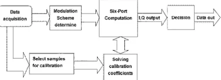
Fig. 4. Flowchart of six-port receiver algorithm.
isolation between the RF and LO ports ( ) is less than 21 dB. The transmission coeffi- cients are close to the theoretically predicted value ( 6 dB). The measured transmission losses are higher than the simulated counterparts, which might be partly because of the effects of K connectors in the measurement, and the offset of metallic holes location restricted to the fabrication limitation.
IV. RECEIVER ALGORITHMS
the signals are thus demodulated. This process is a universal demodulation algorithm for six-port receivers. Most calibration algorithms proposed for six-port reflectome- ters (SPRs) are based on the physical calibration method [13]. This method is accomplished simply by measuring a number of (usually at least nine) arbitrary, but different external physical terminations at input ports. However, for a wireless receiver, this physical calibration method is entirely impractical. It is, there- fore, necessary to develop a calibration method free from any external connection. As an application for a direct receiver, online six-port calibra- tion technologies were under development over the past years. Some calibration algorithms have been proposed. In the pro- posed receiver platform, a real-time six-port calibration method [14] is adopted and the demodulation results for different mod- ulation schemes are analyzed. For the six-port receiver, the ratio of amplitude, frequency, and phase between the LO signal (port 1) and RF signal (port 2) can be calculated from the power output at the other four ports with the complex constants known by calibration procedures. For a six-port receiver circuit, normally the leakage of the re- ceived signal to the LO reference port is small and may be ne- glected. In this case, the relationship between the output data of the SPR and the three power ratios of the detectors of the six-port become linear, and can be expressed as follows:
Xi=Axp1+Ax2p2+Ax3p3+Cx --- (1)
Yi=Ayp1+Ay2p2+Ay3p3+Cy --- (2)
TABLE II
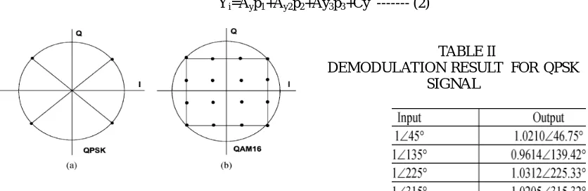
DEMODULATION RESULT FOR QPSK SIGNAL
Fig. 5. Signal constellations for: (a) QPSK and (b) QAM16 modulation.
TABLE III
DEMODULATION RESULT FOR QAM16 SIGNAL
where Xi and Yi are the calculated output data, where as Axj,Ayj (j=1,2,3) and are calibration parameters be
determined. p1 p2 and p3 are power ratios at the output detectors of the six-port.
and III. With the use of MATLAB 6.5 for six-port computation, the demodulation results show that the receiver has accuracy at 5 in phase and 0.4 dB in amplitude for QPSK and QAM16 modulations.
In certain cases, for example, for some modulation scheme, the demodulation signal can be extracted directly from the re- lationship of power detectors output signal level. Therefore, the calibration procedure can be omitted and the demodulation al- gorithm could be simplified [9].
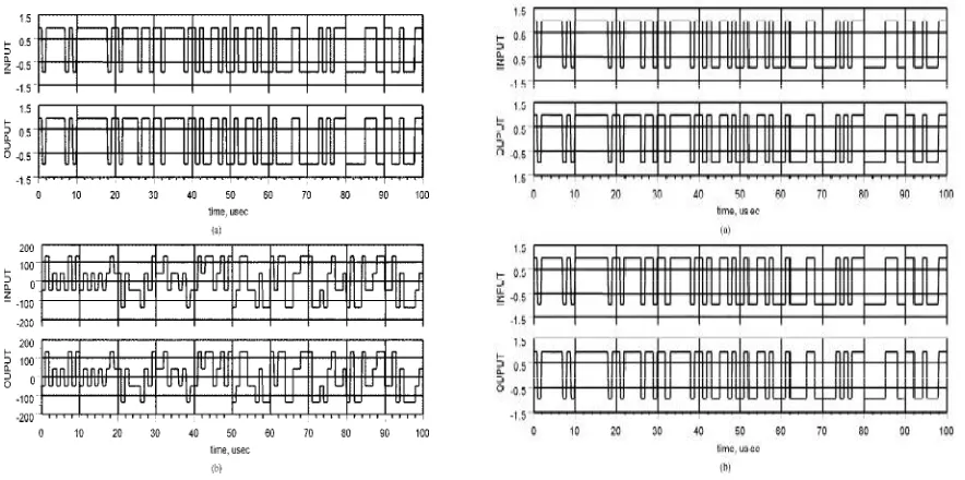
Fig. 6. Input and output waveforms of QPSK signals (a) Signal amplitude. (b) Signal phase. Fig. 7. Input and output waveforms of QAM16 signals. (a) Signal amplitude.
(b) Signal phase.
V. TEST RESULTS
Within the operating frequency band of the receiver (22–26 GHz), two modulation schemes (i.e., QPSK, QAM16) are selected to test performances of the proposed SDR re- ceiver. System-level simulation is made using HP-ADS and MATLAB-Simulink, and the bit error rate (BER) measurement results of the proposed receiver platform are also presented.
The simulated input and output amplitudes and phases of QPSK signals are given in Fig. 6. The INPUT is pseudorandom bit sequence QPSK signals at the input of the vector modulator. The OUTPUT is the same bit sequence, which is demodulated after six-port computation and decision. It can be seen the input signals and output signals are exactly the same, which confirms the operating principle of the proposed SDR receiver.
The simulated input and output amplitudes and phases of QAM16 signals are given in Fig. 7. In the same way as that of the QPSK signal in Fig. 6, the INPUT is a pseudorandom bit sequence QAM16 signal and the OUTPUT is the demodulated signal after six-port computation and decision. The input and output signals are matched very well.
Figs. 8 and 9 show the simulated output signal constellations for both QPSK and QAM16 with various signal-to-noise ra- tios (SNRs). A white signal-to-noise is added to the input signal and the output signal constellations are presented in Fig. 8(a)–(c) for the QPSK signal with SNR equal to 25, 10, and 5 dB, respectively. Demodulation results (after decision algorithms) are presented in Fig. 8(d). Fig. 9(a)–(c) shows the QAM16 signal with SNR equal to 30, 15, and 8 dB, respectively. Demodulation results (after decision algorithms) are presented in Fig. 9(d). It is found that the output constellation is definitely stable. The signal is correctly demodulated if the SNR has an acceptable value.
generated using an HP-8782B vector signal modulator. The modulated signals and reference signals are up-converted to 24 GHz by an Anritsu MG3694A signal generator and two SU26A21D sideband up-converters and then connected to the SIW six-port circuit. The output signals from the six-port circuit are sent to four Wiltron 75KC50 RF power detectors and the RF signals from the six-port output ports are then down-converted to baseband. The baseband signals from power detectors are then sent to two synchronized Altera FPGA DSP boards passing through a Texas Instruments Incorporated four-channel THS7002 programmable-gain amplifier evalua- tion module where the signals are 20 dB amplified and 20 MHz low-pass filtered. The signals are digitalized by four AD9433
Fig. 10. Block diagram of BER measurement setup. Fig. 11. Test-bed setup for receiver performance evaluation.
ADC integrated in two FPGA boards. The receiver algorithms are implemented in the two FPGA processors. The BER ana- lyzer receives the demodulated signal from DSP board1 and evaluates the BER values of the receiver system. An additional white noise generator Agilent N8975A is used for the adjacent signal interference or noise measurements. Fig. 11 shows a photograph of our test setup. It consists of one RF signal generator, one vector signal modulator, one dc power supply, one 3-dB power divider and two RF up-converters, an SIW six-port with RF power
Fig. 8. Simulated output signal constellations for QPSK with different SNR.
detectors, one baseband amplifier evaluation module board, and two FPGA development boards. Simulated and measured BER versus for the two mod- ulation schemes are presented in Figs. 12 and 13, where is the average energy of a modulated bit and is the noise power spectral density. The QPSK and QAM16 signals are generated from a vector modulator without coding. The simulated BER re- sults are obtained from MATLAB-Simulink with carrier RF fre- quency from 22 to 26 GHz, considering the same conditions of power inputs and interferences. The measured BER curve is ob- tained at the center frequency (24 GHz) of the receiver platform. It can be seen that the simulated and measured BER curves are in excellent agreement. It is observed that the receiver
BER is less than 1E-6 for Eb/N0 higher than 10.5 dB (QPSK) and 15 dB (QAM16).
Fig. 12. Simulated and measured BER for QPSK signal. Fig. 13. Simulated and measured BER for QAM16 signal.
VI. CONCLUSION
This paper has presented recent results obtained on the anal- ysis of SDR technology in a direct six-port receiver designed for multimode RF and millimeter-wave communications. A six-port SDR receiver platform has been analyzed and imple- mented [15]. This platform adopts a new SIW six-port structure at the RF front-end, which realizes wideband direct down con- version for low-cost and mass-producible SDR applications. Based on the six-port front-end, the demodulation algorithms have been designed and the demodulation results and BER performance of the SDR receiver for two different modulation schemes (QPSK, QAM16) have been described. The simula- tion and measurement results are very encouraging, showing a possible universal receiver solution for future software-defined radio applications in various wireless communication systems. Our current effort is to implement orthogonal frequency divi- sion multiplexing (OFDM) demodulation in this SDR receiver platform.
REFERENCES
[1] J. Mitola, “The software radio architecture,” IEEE Commun. Mag., pp. 26–38, May 1995.
[2] J. Mitola, “Software radio technology challenges and opportunities,” presented at the 1st Eur. Software Radios Workshop May 1997. [3] W. Tuttlebee, “The impact of software radio,” presented at the Software Radio Workshop Brussels, Belgium, May 1997
[4] D. L. Tennenhouse and V. G. Bose, “The spectrumware approach to wireless signal processing,” Wireless Networks, vol. 2, no. 1, pp. 1–12, Jan. 1996.
[5] V. Bose, M. Ismert, M. Welborn, and J. Guttag, “Virtual radios,” IEEE J. Sel. Areas Commun., vol. 17, no. 4, pp. 591–602, Apr. 1999.
[6] J. Li, R. G. Bosisio, and K. Wu, “Computer and measurement simu- lation of a new digital receiver operating directly at millimeter-wave frequencies,” IEEE Trans. Microw. Theory Tech., vol. 43, no. 12, pp. 2766–2772, Dec. 1995.
[7] J. Hesselbarth, F. Wiedmann, and B. Huyart, “Two new six-port reflec- tometers covering very large bandwidths,” IEEE Trans. Instrum. Meas., vol. 46, no. 4, pp. 966–970, Aug. 1997.
[8] M. Abe, N. Sasho, R. Morelos-Zaragoza, and S. Haruyama, “An RF architecture for software defined receivers,” presented at the Microw. Workshop & Exhibition Yokohama, Japan, Dec. 2002.
[9] S. O. Tatu, E. Moldovan, K. Wu, and R. G. Bosisio, “A new direct millimeter-wave six-port receiver,” IEEE Trans Microw. Theory Tech., vol. 49, no. 12, pp. 2517–2522, Dec. 2001.
[11] D. Deslandes and K. Wu, “Integrated microstrip and rectangular wave- guide in planar form,” IEEE Microw. Guided Wave Lett., vol. 11, no. 2, pp. 68–70, Feb. 2001.
[12] K. Wu, “Integration and interconnect techniques of planar and non- planar structures for microwave and millimeter-wave circuits—Current status and future trend,” in Asia–Pacific Microw. Conf., Taipei, Taiwan, R.O.C., Dec. 3–6, 2001, pp. 411–416.
[13] G. F. Engen, “Calibrating the six-port reflectometer by means of sliding terminations,” IEEE Trans Microw. Theory Tech., vol. MTT-26, no. 12, pp. 951–957, Dec. 1978.
[14] Y. Xu and R. G. Bosisio, “On the real time calibration of six-port receivers (SPRs),” Microw. Opt. Technol. Lett., vol. 20, no. 5, pp. 318– 322, 1999.