ESTIMATION OF ANTENNA FACTOR OF
MICROSTRIP PATCH ANTENNA AS EMI SENSOR
S. Ghosh, A. Roy, and A. Chakrabarty
Kalpana Chawla Space Technology Cell Department of Electronics & Electrical Communication Engineering
Indian Institute of Technology Kharagpur-721302, India
Abstract—This paper presents the result for antenna factor of microstrip patch antenna when used as electromagnetic interference (EMI) sensor. Antenna factor is an important parameter of a sensor used for EMI measurements. The microstrip antenna has found wide application as transmit and receive antenna in modern microwave systems. In this paper, a new application of microstrip antenna as EMI sensor is presented. The result for antenna factor versus frequency of a microstrip patch antenna is presented using commercial software CST Microwave Studio. Also the experimental results for a prototype antenna are presented and compared with the simulated result.
1. INTRODUCTION
useful alternative to the heavy waveguide structures as EMI sensors. This paper presents the initial investigation on the performance of this antenna as EMI sensor in terms of the antenna factor. The ratio of incident electric field at the surface of the sensor to the received voltage at the antenna terminal when terminated in 50 Ω load is known as antenna factor [13]. The results have been achieved as the output of the commercial software CST Microwave Studio [14]. Also the prototype antenna is fabricated and the experimental data is presented for comparison. The results show well agreement.
2. ANTENNA FACTOR
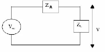
The most common performance descriptor of an EMI sensor is its antenna factor. When an antenna is used as an EMI sensor, it is exposed to an electromagnetic field. This incident field generates a voltage at the antenna terminal, which is read on the receiver/spectrum analyzer. The antenna factor is the factor by which one would multiply the output voltage of a receiving antenna to obtain or recover the incident electric field. The ratio of incident electric field on the surface of the sensor to the received voltage at the antenna terminal when terminated by 50 Ω load is known as antenna factor [13]
antenna f actor=(incident electric f ield(Ei))/(received voltage(V)) (1)
Here Ei is the incident electric field with the polarization giving maximum output and V is the output voltage developed across the load.
Figure 1. Equivalent circuit diagram of an EMI sensor.
replaced by an equivalent open circuit voltageVocat the two terminals of the antenna and its impedanceZA. The open circuit voltageVoc at the gap of the antenna is related to the incident electric field on the antenna surface.
3. ANTENNA CONFIGURATION
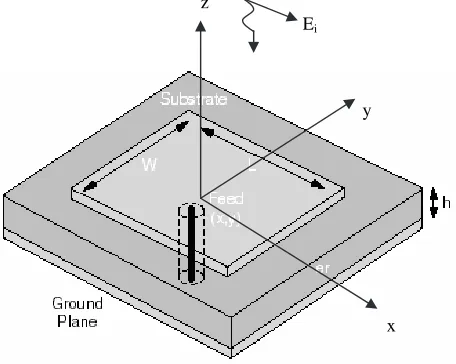
The geometry of the patch antenna, which is illuminated by a plane wave, is shown in Fig. 2. The dimensions are calculated for resonant frequency 2.8 GHz following the formulae available in literature [15].
z
Ei
y
x
Figure 2. Patch antenna illuminated by plane wave.
Here W = width of the patch
L= Length of the patch
h = height of the substrate (x, y) = position of feed
εr= permittivity of the substrate
4. SIMULATION RESULTS
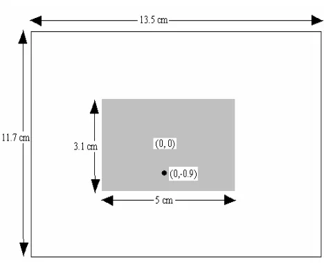
Figure 3. Dimensions of fabricated patch antenna.
For the simulation of antenna factor, the antenna is illuminated by a plane wave normally incident on the patch. The antenna factor is evaluated from the voltage developed across the 50 Ω load connected at the antenna terminal.
5. EXPERIMENTAL RESULTS
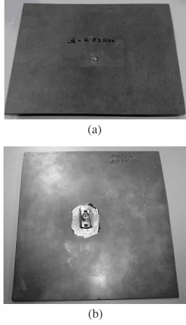
(a)
(b)
Figure 4. Fabricated patch antenna (a) Top view; (b) Bottom view-coaxial probe feed.
and by using a Spectrum Analyzer to measure the received power at the frequency of measurement.
A S-band horn (inside dimension 7.214 cm ×3.404 cm; outside dimension 26.5 cm×221cm) is used. The experiment is carried out over the frequency range of 2 GHz to 3 GHz, with the microstrip patch as sensor. The loss due to transmit and receive antenna-side cables are first determined using the HP 8757C Scalar Network Analyzer. The gain G, of the transmitting horn is determined by using two identical horns as transmit and receive antenna respectively and measuring their power by spectrum analyzer. The gain of the horn is calculated by using the following equation:
G= (4πR/λ)·(PR/PT)1/2. (2) wherePT andPRare the transmitted and received power respectively andRthe distance between the two identical horns. In the experiment performed, R is kept equal to 195.6 cm. The data for determination of cable loss and gain of the horn are presented in Tables 1and 2 respectively.
Table 1. Calibration for cable loss.
Frequency (GHz)
Cable loss CLT x
(dB)
Cable loss CLRx
(dB)
Transmitted PowerPT
(dBm)
2.1 0.8 0.2 12.2
2.2 0.9 0.19 12.1
2.3 0.7 0.2 12.3
2.4 0.6 0.18 12.4
2.5 0.7 0.3 12.3
2.6 1.2 0.2 11.8
2.7 1.0 0.19 12.0
2.8 1.1 0.3 11.9
2.85 1.0 0.2 12.0
2.9 1.2 0.19 11.8
2.95 1.2 0.3 11.8
3.0 0.9 0.2 12.1
3.1 1.0 0.17 12.0
Table 2. Calculation of gain of transmitting antenna.
Frequency (GHz)
Power received by horn (dBm)
20 log λ 4πR dB Gain of horn G (dB) Field strength at plane of sensor (V/m)
2.1 −36.22 −44.71 −3.71 0.33
2.2 −32.96 −45.11 0.053 0.51
2.3 −28.74 −45.49 4.46 0.86
2.4 −28.16 −45.86 5.31 0.96
2.5 −27.92 −46.22 6.0 1.03
2.6 −26.95 −46.56 7.81 1.19
2.7 −25.53 −46.89 9.36 1.46
2.8 −22.84 −47.21 12.47 2.07
2.85 −14.94 −47.36 20.42 5.23
2.9 −15.77 −47.51 19.94 4.84
2.95 −15.72 −47.66 20.14 4.95
received by the sensor was measured using a Agilent CSA N1996 A-503 Spectrum Analyzer. Loss due to the connecting cables is taken into account. The field strength at the plane of the sensor placed at a distancedfrom the transmit antenna for normal incidence is obtained from the following equation
E = (60PTG)1/2/d V/m. (3)
The voltage at the sensor terminals, VM, is calculated from the measured power, PM assuming a measuring device with an input impedance of 50 Ω for the Spectrum Analyzer, as follows
VM = (50PM)1/2. (4)
The antenna factor (AF) is then evaluated as follows
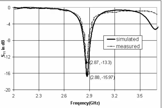
AF = |E|/VM m−1 (5) = 20 log10(|E|/VM) dB m−1. (6) The return loss of the patch antenna is measured using scalar network analyzer. The experimental and simulated results of return loss are presented in Fig. 5. The antenna factor versus frequency plot is shown in Fig. 6.
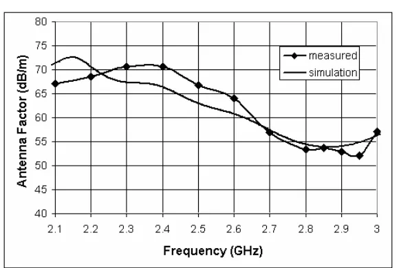
Figure 6. Antenna factor in dB/m versus frequency of microstrip patch antenna.
6. DISCUSSIONS
The measured data of return loss of the microstrip patch antenna shows well agreement with the simulated result (Fig. 5). Also the measured and simulated antenna factor data shows the same pattern over the frequency band of interest, though a maximum difference of ∼ 6 dB is noticed (Fig. 6) at some frequency points. The possible reasons for this deviation in measured and simulated results are summarized as follows:
• The mismatch produced by the cables on transmit and receive side will contribute to the measurement error significantly.
• Though the scattering by other reflecting bodies in the vicinity are tried to minimize, can not be removed totally.
• Errors in calibrating the horn, cables, orienting the sensor with respect to the transmitting horn may incorporate error in the measured values of antenna factor.
Also further study is required for the near field correction to the antenna factor of the patch antenna.
7. CONCLUSION
A very interesting application of microstrip patch antenna as EMI sensor is presented. The antenna factor of this antenna over a frequency range is evaluated for an incident EM radiation from a distant antenna. The simulated result shows same trend as the experimental data. The result for antenna factor of the patch antenna encourages the application of this antenna as EMI sensor.
REFERENCES
1. Ghosh, S., A. Chakrabarty, and S. Sanyal, “Loaded wire antenna as EMI sensor,”Progress In Electromagnetics Research, PIER 54, 19–36, 2005.
2. Ghosh, S., A. Chakrabarty, and S. Sanyal, “Estimation of antenna factor of wire antenna as EMI sensor,”Journal of Electromagnetic Waves and Applications, Vol. 16, No. 1, 2002.
3. Ghosh, S. and A. Chakrabarty, “Performance analysis of EMI sensor in different test sites with different wave impedances,” Progress In Electromagnetics Research, Vol. 62, 127–142, 2006. 4. Ghosh, S. and A. Chakrabarty, “Estimation of equivalent circuit of
loaded trans-receive antenna system and its time domain studies,” Journal of Electromagnetic Waves and Applications, Vol. 20, 89– 103, 2006.
5. Ali, M. and S. Sanyal, “FDTD analysis of dipole antenna as EMI sensor,” Progress In Electromagnetics Research, PIER 69, 341– 359, 2007.
6. Das, S. and A. Chakrabarty, “A novel modeling technique to solve a class of rectangular waveguide based circuits and radiators,” Progress In Electromagnetics Research, Vol. 61, 231–252, 2006. 7. Bhattacharya, A., S. Gupta, and A. Chakraborty, “Analysis
of rectangular waveguides and thick windows as EMI sensors,” Progress In Electromagnetic Research, PIER 22, 231–258, 1999. 8. Pozar, D. M., “Microstrip antennas,”Proc. IEEE, Vol. 80, No. 1,
79–91, January 1992.
10. Bernardi, P. and R. Cicchetti, “Response of a planar microstrip line excited by an external electromagnetic field,” IEEE Trans. Electromagn. Compat., Vol. 32, No. 2, 98–105, May 1990.
11. Bernardi, P., R. Cicchetti, and D. S. Moreolo, “A full-wave model for EMI prediction in planar microstrip circuits excited in the near field of a short electric dipole,” IEEE Trans. Electromagn. Compat., Vol. 37, No. 2, 175–182, May 1995.
12. Cooray, F. R. and J. S. Kot, “Analysis of radiation from a cylindrical-rectangular microstrip patch antenna loaded with a superstrate and an air gap, using the electric surface current model,” Progress In Electromagnetics Research, PIER 67, 135– 152, 2007.
13. Paul, C. R., Introduction to Electromagnetic Compatibility, 2nd edition, John Wiley & Sons Inc., New York, 1992.
14. CST Microwave Studio, version 5 manual.
15. Balanis, C. A., Antenna Theory Analysis and Design, 2nd ed., John Wiley & Sons, New York, 1997.
16. Ang, B. K. and B. K. Chung, “A wideband E-shaped microstrip patch antenna for 5–6 GHz wireless communications,”Progress In Electromagnetics Research, PIER 75, 397–407, 2007.
17. Abdelaziz, A., “Bandwidth enhancement of microstrip antenna,” Progress In Electromagnetics Research, PIER 63, 311–317, 2006. 18. Gao, S. and A. Sambell, “A simple broadband printed antenna,”
Progress In Electromagnetics Research, PIER 60, 119–130, 2006. 19. Abbaspour, M. and H. R. Hassani, “Wideband star-shaped