A NOVEL RADIATION PATTERN AND FREQUENCY RECONFIGURABLE MICROSTRIP ANTENNA ON A THIN SUBSTRATE FOR WIDE-BAND AND
WIDE-ANGLE SCANNING APPLICATION
J. Ouyang,F. Yang,S. W. Yang,Z. P. Nie,and Z. Q. Zhao
School of Electronic Engineering
University of Electronic Science and Technology of China (UESTC) Chengdu 610054, China
Abstract—A novel radiation pattern and frequency reconfigurable microstrip antenna is introduced in this paper. This antenna is designed on a thin substrate for the application of conformal phased antenna future. The proposed antenna make the operating frequency range 6 times larger than that of a simple rectangular microstrip antenna, and make the beam covering from−70◦∼70◦ compared with the traditional rectangular microstrip antenna beam which only covers
−50◦∼50◦. It is potential on the application of band and wide-angle scanning.
1. INTRODUCTION
Microstrip antennas have been widely used in conformal phased array owing to their distinct advantages such as light weight and small size. But conformal phased array antennas need a lower section for keeping flying capability of aircraft. At the same time, the thin substrate makes a narrowband characteristic affect the available application in conformal phased array. Many efforts have been devoted to the bandwidth enhancement of microstrip antennas, and many techniques have been proposed [1–4, 8, 9]. But with a limit of thin substrate, the antenna has 3 times bandwidth improvement compared with the traditional rectangular microstrip antenna at best. However, the proposed reconfigurable microstrip antenna makes the operating frequency range 6 times larger than that of a simple rectangular microstrip antenna.
rectangular microstrip can not be used for a wide-angle scanning exceeding 50◦, because it only has a beam width 100◦ inE-plane and 110◦ in H-plane. In [5–7, 10], switching mechanisms are utilized to alter the current paths and provide pattern reconfigurable behavior. In this paper, the proposed microstrip antenna also has an ability to reconfigure radiation pattern that take a 3 dB space covering from
−70◦ ∼ 70◦. So the useful antenna, proposed in this paper, can be used in board-band and wide-angle application in conformal phased array future.
2. ANTENNA STRUCTURE
The proposed frequency and radiation pattern reconfigurable antenna can be separated into two components. One is the frequency reconfigurable component. Another is the radiation pattern reconfigurable component. The frequency reconfigurable component at the right top corner of Fig. 1(a), is composed by a square microstrip antenna and a coupling strip. The radiation pattern reconfigurable component at the right underside corner of Fig. 1(a), is composed by a small square microstrip antenna which size is nearlyλg/2 and a big
square microstrip antenna which size is nearlyλg. The blank rectangles
in the Fig. 1 indicate the switches, which can be described as the FRSs (frequency reconfigurable switches) and PRSs (pattern reconfigurable switches). The FRSs are the blank rectangles which are shown at the right top corner of Fig. 1. The PRSs are the blank rectangles which are shown at the right underside corner of Fig. 1.
(a) (b)
It is a frequency reconfigurable antenna with a board side radiation pattern, when turning the inside FRSs on, outside FRSs and the PRSs off. When turning the PRSs and outside FRSs on, inside FRSs off, the antenna becomes another frequency reconfigurable antenna with a divisive pattern. And, it also can achieve radiation pattern reconfiguration by turning the PRSs on/off. The interior FRSs control the frequencies of the small square microstrip antenna which works on the basal mode. The exterior FRSs control the frequencies of the large square microstrip antenna which works on the high-order mode.
Figure 1(b) is the photograph of the proposed antenna. The switches are replaced by a conterminous wire in the experimentation. The parameters of the width and length of the small square patch are 31 mm∗31 mm. The size of the big rectangle patch is 61 mm∗61 mm. The width of the gap between the patch and the coupling strip is 0.5 mm. The feed point is built at the place which has a space 5 mm from the square center. The feed probe radius is 0.5 mm. The height of the substrate is 1 mm (0.01λ0), and its dielectric constant is 2.55.
3. RESULT AND DISCUSSION
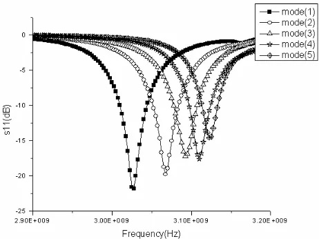
Figure 2 shows the experiment frequency reconfigurable situation by turning the PRSs, outside FRSs off and inside FRSs on. The different frequencies are acquired by inside FRSs on in turn. And the antenna has a board-side pattern in this time. It is obvious that the proposed
Figure 3. The frequency reconfiguration with exterior FRSs.
(a) (b)
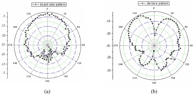
Figure 4. The pattern reconfiguration by turning PRSs on/off, (a) experimental pattern by turning PRSs off, (b) experimental pattern by turning PRSs on.
by turning PRSs on/off. Fig. 4(a) shows a board-side pattern in E-plane when turning PRSs off. Fig. 4(b) shows a board-side pattern in E-plane when turning the PRSs on. It is obvious that the PRSs can control the antenna pattern and make beam covering from−70◦ ∼70◦. 4. CONCLUSION
A novel radiation pattern and frequency reconfigurable microstrip antenna is introduced in this paper. This antenna is designed on a thin substrate. The proposed antenna makes the operating frequency range 6 times larger than that of a simple rectangular microstrip antenna, and Compared with the traditional rectangular microstrip antenna beam which only covers −50◦ ∼ 50◦, the proposed antenna also make the beam covering from −70◦ ∼70◦. With a lower section, this structure would be greatly suitable for conformal phased array applications in future.
ACKNOWLEDGMENT
This work was supported Partly Supported by the National Natural Science Foundation of China (No. 60771042, No. 10876007), 863 Program (No. 2007AA12Z159), 111 Project (No. B07046) and the Program for New Century Excellent Talents in University of China. REFERENCES
1. Pues, H. F. and A. R. Van De Capelle, “An impedance-matching technique for increasing the bandwidth of the microstrip antennas,” IEEE Transactions on Antennas and Propagation, Vol. 37, No. 11, 1345–1354, November 1989.
2. Aanaandan, C. K., P. Mohanan, and K. G. Nair, “Broad-band gap coupling microstrip antenna,” IEEE Transactions on Antennas and Propagation, Vol. 38, No. 10, 1581–1585, October 1990. 3. Fang, S.-T., K.-L. Wong, and T.-W. Chiou, “Bandwidth
enhancement of inset-microstrip-line-fed equilateral-triangular microstrip antenna,” Electronics Letters, Vol. 34, No. 23, 2184– 2185, November 12, 1998.
5. Maloney, J. C., M. P. Kesler, L. M. Lust, L. N. Pringle, T. L. Fountain, and P. H. Harms, “Switched fragmented aperture antennas,” PROC. IEEE Antennas Propagat. Soc. Int. Symp., Vol. 1, 310–313, 2000.
6. Vinoy, K. J., K. A. Jose, V. K. Varadan, and V. V. Varadan, “Hilbert curve fractal antennas with reconfigurable characteris-tics,”Proc. EEE MTT-S Int. Microw. Symp. Digest, Vol. 1, 381– 384, 2001.
7. Huff, G. H., J. Feng, S. Zhang, and J. T. Bernhard, “A novel radiation pattern and frequency reconfigurable single turn square spiral microstrip antenna,” IEEE Microwave Wireless Components Letter, Vol. 13, 57–59, February 2003.
8. Ansari, J. A. and R. B. Ram, “E-shaped patch symmetrically loaded with tunnel diodes for frequency Agile/broadband operation,”Progress In Electromagnetics Research B, Vol. 1, 29– 42, 2008.
9. Wang, Y. J. and C. K. Lee, “Compact and broadband microstrip patch antenna for the 3g Imt-2000 handsets applying styrofoam and shorting-posts,” Progress In Electromagnetics Research, PIER 47, 75–85, 2004.