Available online:
https://edupediapublications.org/journals/index.php/IJR/
P a g e | 516Analysis of bidirectional dc-dc converter interfacing ultracapacitor
using PV cells
Vaddemoni Swarna Rekha
[email protected]
A BSTRA CT: This paper highlights the controller of a bidirectional converter to interface an ultra-capacitor as storage device to renewable energy systems. Ultra capacitors are typically used in renewable energy systems to improve the system's reliability and energy conversion efficiency. The controller of the converter system has been designed and simulated based on the integration of both Current Mode Control and Linear Quadratic Regulator methods. The controller performance is tested under different modes of operating conditions in bidirectional converter using MATLAB/Simulink simulation package. The simulation results show that a good DC bus voltage regulation is achieved in the tested conditions. In addition to that, the controller ensures smooth transition between the buck and boost modes of the bidirectional converter operation.
Index Terms—bidirectional converter; ultra-capacitor; peak current mode control; linear quadratic regulator.
I. INTRODUCTION
In recent days, the number of applications which requiremore than one power source is increasing. Distributedgenerating systems or micro-grid systems normally usemore than one power source or more than one kind ofenergy source. Also, to increase the utilization of renewableenergy sources, diversified energy source combination isrecommended. The combination of more power sources anddiversified power sources make it possible to obtain higheravailability in a power system. A parallel connection ofconverters has been used to integrate more than one inputenergy source in a power system. However, a MIC [1]-[4]can generally have the following advantages compare to acombination of several individual converters like cost reduction, compactness, more expandability and greatermanageability. MICs are being used in aerospace, electricand hybrid vehicles, sustainable energy sources andmicrogrid applications.The widespread industrial use of induction motor(IM) has been stimulated over the years by theirrelative cheapness, low maintenance and highreliability. The control of IM variable speed drivesoften requires control of machine input
voltage, whichis normally achieved by using a voltage sourceinverter.Amongst storage devices, ultracapacitor is preferred due toits long life-time, good electrical behavior and to its relativelylow initial cost in comparison with modern batteries [5]. Inaddition, it is positively characterized by its high powerdensity, low losses while charging and discharging, and it’svery low equivalent series resistor (ESR) which allows it todeliver and absorb very high currents and to be charged veryquickly [6-7].Furthermore, ultracapacitor can provide largetransient power instantly [8].
Various control methods have been proposed in the literature to interface renewable energy sources with a storagedevice using a bidirectional converter. The authors in reference[8] applied the dynamic evolution control method to interfacea fuel cell and the ultracapacitor.
In literature [5], the PIcontroller was designed for the integration of wind energyconversion system and ultracapacitor.
The current programmedmode (CPM) duty ratio control and linear PI compensator wasreported in [8] for controlling a bidirectional converterinterfacing wind energy conversion and battery storage system.
A combination of both fuzzy and sliding-mode controlstrategies to interface the wind energy conversion system andthe storage device has been proposed in [8].
Available online:
https://edupediapublications.org/journals/index.php/IJR/
P a g e | 517 (PCMC) is the most common one in which thepeakvalue of the inductor current is sensed and compared withthe current reference for the generation of the PWM signal[7].
Another control method that is most cited for controllingthe PWM converters is linear quadratic regulator (LQR)control [8]. Since the controller feedback gain-vector isdetermined optimally in LQR, the designers can guarantee thatthe converter has good closed-loop behavior, and is relativelyinsensitive to system parameter variations or external
II. M o d elin g o f th e Ultra cap acito r an dBidirectional DC-DC Co n v erter
Fig. 1. The electrical circuit of ultra-capacitor-bidirectional DC-DC convertertopology
Fig. 2.The small-signal model of PCMC converter.
𝐹𝑚 = 1 (𝑀1+ 𝑀𝑐)𝑇𝑠
… … … … 2
𝑘𝑓 = −𝑇𝑠𝑅𝑖
2𝐿 ………….3
𝑘𝑟 = −𝐷′2𝑇
𝑠𝑅𝑖
2𝐿 … … … … .4
WhereM1 is the rising slope of the inductor current,
Mcis the slope of the artificial ramp signal that is
used for slopecompensation. It is stated that there is an inherentstability when D > 0.5 for all types of
converters. In order toguarantee the controller stability for all ranges of the duty-cycle, an artificial ramp with slope Mc≥ 0.5M2 has to
beadded ( M2 ) is the falling slope of the inductor
current).Ts isthe switching period. As it is very
small, the krcan beneglected.
Based on Fig. 2, when kr is neglected, the duty ratio
lawcan be expressed as:
𝑑̂ = 𝐹𝑚(−𝑅𝑖𝑖̂ + 𝑘𝐿 𝑓𝑣̂ + 𝑣𝑖𝑛 ̂ ) … … … … . .5𝑐
III. Th e Lin ear Qu ad ratic Reg u lato r– Cu rren tM o d e
As aforementioned, the objective of the controller in thispaper is to ensure a good voltage regulation at the DC bus.Thus, the small signal model of the CMC boost converter isaugmented to include the new feedbacks from the statevariables of the converter. In addition, a new state variable, theerror between the reference and the output voltage, is added, asshown in Fig. 3.
𝜉̂ = 𝑥
̂ = 𝑉
3̂ − 𝐶𝑥̂
𝑟𝑒𝑓With the new state-space vector 𝑋̂ = [𝑎
𝑥
̂𝜉
̂]
, the
augmented small-signal model can be written
as,
𝑋
̂ = [
𝑎𝐴
2×20
2×1−𝐶
1×20
1×1] [𝑋
̂
𝜉̂
] + [
𝑏1
2×10
1×1]𝑣
̂
𝑖𝑛+ [
𝑏2
0
2×11×1
] 𝑣
̂
𝑐+ [
0
𝐼
2×11×1
] 𝑣
𝑟𝑒𝑓+ [
𝑏3
2×10
1×1]𝑖
̂
0̂
where the matrices A and B are obtained from the small signalstate-space model of the CMC PWM DC-DC boost convertersystem in (6). C=[0 1].
Available online:
https://edupediapublications.org/journals/index.php/IJR/
P a g e | 518 Fig. 3. The small signal model of closed-loop CMCPWM boost converter withlinear feedback control.
IV. EXPERIM ENTA L RESULTS
In this section, the MATLAB/Simulink simulation resultsfor different operation modes of the bidirectional converter thatinterfaces the ultracapacitor to the DC bus are depicted anddiscussed. The simulated system diagram is shown in Fig. 4,and the used parameters for the converter and the ultracapacitorare listed in Table I.
Fig. 4.The block diagram of the proposed interfacing system.
When the renewable source current was maintained at 10 A
Fig.5 Constant source current
The response of a step variation in the load current from 5A to 15A and then to 5A, when the source current is fixed at 10A.
Fig. 6 Load current when source current is constant The response of a step variation in ultra capacitor current from 5A to 15A and then to 5A, when the source current is fixed at 10A. By charging and discharging modes of operation.
Fig.7 ultra capacitor current when source current is constant
The load current was changed in steps from 5 A to 15 A and then to 5 A. In the first interval (between t=0 and t=0.02 s) the renewable source covered the load demand and injected its excess current to the ultra capacitor. In this interval, the bidirectional converter operated in a buck mode. When an additional 10 A was required by the load (between t=0.02 and t=0.05 s), the renewable source was unable to provide the full load demand. Thus, the bidirectional converter acts as boost mode to discharge the ultra capacitor and supply the extra load demand (5 A).
0 0.01 0.02 0.03 0.04 0.05 0.06 0.07 0.08 -10
-5 0 5 10 15
20 source current
time (msec)
cu
rr
en
t
(a
m
p
)
0 0.01 0.02 0.03 0.04 0.05 0.06 0.07 0.08 -10
-5 0 5 10 15 20
time (msec)
c
u
rr
e
n
t
(a
m
p
)
0 0.01 0.02 0.03 0.04 0.05 0.06 0.07 0.08 -10
-5 0 5 10 15 20
time (msec)
cu
rr
e
n
t (a
m
p
Available online:
https://edupediapublications.org/journals/index.php/IJR/
P a g e | 519 Fig.8 Combination of Load &ultra capacitorcurrents
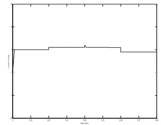
Fig .9 Reference voltage fixed at 100 V When the ultra capacitor changing from charging and discharging mode of operation the spikes are obtained at different time intervals.
Fig. 10 output voltage when reference voltage is constant
The DC bus voltage , it was regulated at the desired value 100V . The figure shows clearly for the two modes of operation.
When the source current is varied at different time intervals.Isource was changed from 0 A to 10 A at time of 0.04 sec. Since we are using PWM technique the waveform will be in step variation
Fig.11 The combination of output voltage & reference voltage
Fig. 12 variation in source current
The slight changes obtained in the load current when the source current is varied. The spikes are obtained since we are using capacitor and inductor.
Fig.13 Load current when source current is varied The ultra capacitor current operates in two modes i.e., buck and boost modes. From 0.01 sec the buck mode is operated by charging the ultracapacitor.
0 0.01 0.02 0.03 0.04 0.05 0.06 0.07 0.08 -10
-5 0 5 10 15 20
time (msec)
cu
rr
en
t
(a
m
p
)
0 0.01 0.02 0.03 0.04 0.05 0.06 0.07 0.08
0 20 40 60 80 100 120
time (msec)
vo
lt
a
g
e
(
v
o
lt
s)
0 0.01 0.02 0.03 0.04 0.05 0.06 0.07 0.08 0
20 40 60 80 100 120
time (msec)
v
o
lt
ag
e
(
vo
lt
)
0 0.01 0.02 0.03 0.04 0.05 0.06 0.07 0.08
0 20 40 60 80 100 120
time (msec)
v
o
lt
a
g
e (
v
o
lt
)
0 0.01 0.02 0.03 0.04 0.05 0.06 0.07 0.08 -10
-5 0 5 10 15
time (msec)
c
u
rr
e
n
t
(a
m
p
)
0 0.01 0.02 0.03 0.04 0.05 0.06 0.07 0.08 -10
-5 0 5 10 15
time (msec)
c
u
rr
en
t
(a
m
p
Available online:
https://edupediapublications.org/journals/index.php/IJR/
P a g e | 520 Fig.14 ultra capacitor current when source currentis varied
The combination of both load and ultra capacitor current is shown.
Fig.15 combination of load &ultra capacitor currents
The reference voltage is changing from 100 V to 110 V and again back to 90 V.
Fig.16 Variation in reference voltage
The output voltage obtained when the reference voltage is varied. The boost mode is operated from
0.02 sec to 0.06 sec and remaining in buck mode, here the voltage will be at 110 V .
Fig.17 Output voltage when voltage is varied The combination of both reference voltage and output voltage .
Fig 18 Reference voltage and output voltages
V. CONCLUSION
The LQR-CMC method hasbeen successfully applied to control the bidirectional converterin the case of boost and buck modes. The objectives of thecontroller were to regulate the output voltage and to achieve asmooth transition between the two operation modes of thebidirectional converter, namely buck and boost modes. Inaddition, the proposed controller ensures continuous powersupply the load, regardless of the load and renewable energypower changes. In short, the proposed controller is capable ofincreasing the reliability and energy conversion efficiency ofrenewable energy systems.
REFERENCES
[1]. J. L. Duarte, M. Hendrix, and M. G. Simoes, “Three port bidirectional converter for hybrid fuel cell systems,”IEEE Trans. Power Electron., vol. 22, no. 2, pp. 480–487,Mar. 2007
0 0.01 0.02 0.03 0.04 0.05 0.06 0.07 0.08 -10
-5 0 5 10 15
c
u
rr
e
n
t
(a
m
p
)
0 0.01 0.02 0.03 0.04 0.05 0.06 0.07 0.08 -10
-5 0 5 10 15
time (msec)
c
u
rr
e
n
t(
a
m
p
)
0 0.01 0.02 0.03 0.04 0.05 0.06 0.07 0.08
0 20 40 60 80 100 120
time (msec)
v
o
lt
a
g
e
(
v
o
lt
)
0 0.01 0.02 0.03 0.04 0.05 0.06 0.07 0.08 0
20 40 60 80 100 120
time (msec)
v
o
lt
ag
e
(
v
olt
)
0 0.01 0.02 0.03 0.04 0.05 0.06 0.07 0.08 0
20 40 60 80 100 120
time (msec)
v
o
lta
g
e (
v
o
lts
Available online:
https://edupediapublications.org/journals/index.php/IJR/
P a g e | 521 [2]. F. Z. Peng, H. Li, G. J. Su, and J. S. Lawler, “AnewZVS bidirectional dc–dc converter for fuel cell and batteryapplication,” IEEE Trans. Power Electron., vol. 19, no. 1,pp. 54–65, Jan. 2004.
[3]. L. Yan, R. Xinbo, Y. Dongsheng, L. Fuxin, and C. K.Tse, “Synthesis of multiple-input DC/DC converters,” IEEETrans. Power Electron., vol. 25, no. 9, pp. 2372–2385, Sep.2010.
[4]. A. Kwasinski, “Identification of feasible topologies formultiple-input DC–DC converters,” IEEE Trans. PowerElectron., vol. 24, no. 3, pp. 856–861, Mar. 2010.
[5] J. Leuchter, "Bi-Directional DC - DC Converters for BatteryBuffers with Supercapacitor” in Energy Storage in the EmergingEra of Smart Grids, R. Carbone, Ed., ed: InTech, 2011.
[6] Y. Zhao, et al., "Design on Triple Bi-directional DC/DC ConverterUsed for Power Flow Control of Energy Storage in Wind PowerSystem Communication Systems and Information Technology."vol. 100, M. Ma, Ed., ed: Springer Berlin Heidelberg, 2011, pp. 7-14.
[7] J. Lopes, et al., "Optimal sizing of batteries and ultracapacitors forfuel cell electric vehicles," in IECON 2011 - 37th AnnualConference on IEEE Industrial Electronics Society, 2011, pp. 4603-4608.
[8] A. S. Samosir and A. H. M. Yatim, "Implementation of DynamicEvolution Control of Bidirectional DC-DC Converter forInterfacing Ultracapacitor Energy Storage to Fuel-Cell System,"IEEE Transactions on Industrial Electronics, vol. 57, pp. 3468-3473, 2010.
A u th o r Pro file: