Volume 2008, Article ID 860360,10pages doi:10.1155/2008/860360
Research Article
Postfiltering Using Multichannel Spectral Estimation in
Multispeaker Environments
Hai Quang Dam, Sven Nordholm, Hai Huyen Dam, and Siow Yong Low
Western Australian Telecommunications Research Institute (WATRI), Crawley, WA 6009, Australia
Correspondence should be addressed to Hai Quang Dam, [email protected]
Received 14 September 2006; Accepted 5 July 2007
Recommended by Douglas O’Shaughnessy
This paper investigates the problem of enhancing a single desired speech source from a mixture of signals in multispeaker envi-ronments. A beamformer structure is proposed which combines a fixed beamformer with postfiltering. In the first stage, the fixed multiobjective optimal beamformer is designed to spatially extract the desired source by suppressing all other undesired sources. In the second stage, a multichannel power spectral estimator is proposed and incorporated in the postfilter, thus enabling further suppression capability. The combined scheme exploits both spatial and spectral characteristics of the signals. Two new multichan-nel spectral estimation methods are proposed for the postfiltering using, respectively, inner product and joint diagonalization. Evaluations using recordings from a real-room environment show that the proposed beamformer offers a good interference sup-pression level whilst maintaining a low-distortion level of the desired source.
Copyright © 2008 Hai Quang Dam et al. This is an open access article distributed under the Creative Commons Attribution License, which permits unrestricted use, distribution, and reproduction in any medium, provided the original work is properly cited.
1. INTRODUCTION
Multichannel beamforming techniques can be largely di-vided into three types, namely, fixed, optimum, and adap-tive beamforming [1,2]. For a fixed beamformer, the beam-former weights, which usually consist of FIR-filter weights, are designed to focus into a main source direction while sup-pressing signals from other undesired directions. This lem can be viewed as a multidimensional filter design prob-lem [2]. As such, the weights are calculated based on infor-mation about the array geometry and the source localization with no statistical information about the signal’s environ-ment or the required signals.
Multichannel optimum filtering, on the other hand, re-quires statistical knowledge about the noise statistics, the en-vironment, and the source statistics. The beamformer coeffi -cients are optimized in such a manner that a focussed beam is steered to a desired source direction, whilst suppressing the contributions coming from other directions [2,3]. Similar to the fixed beamformer case, the design also requires informa-tion about the locainforma-tion of the target signal and the array ge-ometry. From those parameters, a spatial, spectral, and tem-poral filter is formed to match the beamforming requirement [4,5].
Adaptive beamforming techniques are developed to track time-varying signal situations [6, 7]. A well-known tech-nique is to combine the beamformer with an adaptive postfil-tering technique. The adaptive postfilpostfil-tering uses the estima-tion of spectral densities of the desired and undesired signals in the filter output to further suppress the noise. One com-mon method to perform postfiltering is spectral subtraction. This method exploits spectral information of the noise and the speech sources to form a gain function to suppress the noise [8,9]. A critical part for spectral subtraction is the de-tection of speech active and inactive periods [10]. The speech inactive periods are used to update the noise statistics. Dur-ing these periods, the noise information is updated in the gain function. Naturally, any misdetection will lead to erro-neous update of the noise and result in distortion. Also, spec-tral subtraction succumbs to nonstationary noise as it relies heavily on speech pauses to update the noise statistics. More explicitly, the noise is estimated during speech pauses and is used to form the gain function during speech periods. As a consequence, spectral subtraction cannot deal well with situ-ations where the interference is another speech source or the noise is nonstationary.
postfilter uses the auto- and cross-spectral densities of the ar-ray inputs to estimate the signal and noise spectral densities. By doing so, the postfilter is capable of performing in non-stationary noise. However, one of the main assumptions in [11] is that the noise in different channels are uncorrelated corresponding to an incoherent noise field. In practice, the correlation of the noise signals between channels may be sig-nificant. This is especially the case for closely spaced sensors, for example, typically in speech enhancement applications. To cope with that, a number of techniques have been pro-posed during the past few years [12,13]. A postfiltering tech-nique based on the complex coherence function for a specific coherence noise field such as spherically isotropic (diffuse) or cylindrically isotropic noise fields is proposed in [12]. In [13], a multichannel postfiltering is developed to minimize the log-spectral amplitude distortion in nonstationary noise environments. A main assumption is made that a desired source component is stronger at the beamformer output than at any reference noisy signal, and the interference compo-nent is the strongest at one of the reference signals. However, this assumption might not be satisfied if the desired source and other undesired interferences are located close to the ar-ray and have fast time-varying characteristics such as speech signals.
This paper aims to recover a particular speech source while rejecting other speech sources in multispeaker environ-ments. This has been referred to as a cocktail party effect or an “attentional selectivity” [14,15]. As an example, consider a situation with many speakers in a “meeting” room. The ob-served signals contain the speech signals from many speakers with the possibility of overlapping one another. The objective is to extract a single desired signal from the mixtures.
A new beamformer structure is proposed which em-ploys a multichannel power spectral estimator of the desired speech source. This structure includes a multiobjective opti-mal beamformer followed by a postfilter. The multiobjective optimal beamformer is designed to spatially extract a desired source while suppressing all other undesired source(s). More specifically, if there are three or more speech sources, the multiobjective optimal beamformer is designed to eliminate at least two undesired sources. As such, it may not be able to suppress all the undesired sources. To suppress further the undesired sources from the beamformer output, an adaptive postfilter is proposed which includes a multichannel tral estimation of the desired signal. Two multichannel spec-tral estimation methods are developed for the postfiltering using, respectively, inner product and joint diagonalization to estimate the desired source power spectral density (PSD). Evaluations using recordings from a real room environment show that the proposed beamformers offer good interference suppression levels whilst maintaining low distortion levels of the desired source.
The organization of the paper is given as follows. The problem formulation is outlined in Section 2. The spatial correlation matrix estimation using calibration signals is de-veloped inSection 3. A fixed multiobjective optimal beam-former is proposed in Section 4. Two multichannel spec-tral estimation methods using, respectively, inner product and joint diagonalization are developed in Section 5.
Fi-Speaker Speaker
Speaker
Speaker
Speaker
Ispeakers
Table L
micr ophones
···
···
···
···
Figure1: Position of sources and the microphone array in multi-speaker environment.
nally, evaluations of the proposed beamformer using real data are presented inSection 6, and conclusions are given in
Section 7.
2. PROBLEM FORMULATION
Consider a multispeaker situation withIspeakers located in the near field of anL-element microphone array as depicted inFigure 1. The speakers can be active in a random manner and their speech signals may overlap in time. Denote bysi(n), 1≤i≤I, anL×1 vector of the discrete-time observed signal from theith source at the microphones wherendenotes the time index. The received signalx(n) at the microphones can be written as
x(n)= I
i=1
si(n) +v(n), (1)
where v(n) is the background noise. Here, we concentrate mainly on the case with speech mixtures. Thus, the termv(n) is being omitted. The task at hand is to extract the desired source(s) from a mixture ofIsources.
The proposed beamformer is performed in the frequency domain. Thus, the received signal is decomposed intoM sub-bands in the frequency domain by using an analysis filter bank [16]. The filtering and processing are then performed for each frequency bin. The observed signalx(ω,k) for each frequency binωand time indexkcan be given as
x(ω,k)= I
i=1
si(ω,k), (2)
statistically independent, the correlation matrix of the re-ceived signalRx(ω,k) at instantkcan be expressed as
Rx(ω,k)= I
i=1
Ri(ω)pi(ω,k). (3)
In the following section, a calibration method will be pre-sented to calculate the source spatial correlation matrices be-fore the beamforming process.
3. SPATIAL CORRELATION MATRIX ESTIMATION USING CALIBRATION SIGNALS
In [19,20], a calibration method is outlined where the train-ing samples of the sources are recorded prior to the beam-forming process. This method is developed to estimate the statistical information of the sources which includes un-known signal path information. By doing so, all the infor-mation on the array geometry and source localization will be reflected in the solution [21].
During the calibration period, each speaker is active for a short period of time while other speakers are silent. Denote by [K1,i,K2,i] the active time of theith source andRi,cal(ω) the correlation matrix forith source estimated during the cali-bration period. This matrix can be obtained as
Ri,cal(ω)= 1
K2,i−K1,i+ 1 K2,i
k=K1,i
x(ω,k)xH(ω,k). (4)
Moreover, denote by di,cal(ω) the spatial cross correlation vector with respect to the th prechosen reference micro-phone, 1≤≤L. The vectordi,cal(ω) is estimated as
di,cal(ω)= 1
K2,i−K1,i+ 1 K2,i
k=K1,i
x(ω,k)x∗(ω,k,), (5)
wherex(ω,k,) is the received signal at theth microphone. The spatial correlation matrixRi(ω) and the spatial cross cor-relation vectordi(ω) can be estimated as
Ri(ω)= Ri,cal(ω)
Ri,cal(ω,,)
, (6)
di(ω)= di,cal(ω)
di,cal(ω,)
, (7)
whereRi,cal(ω,,) is the (,) element of the matrixRi,cal(ω) anddi,cal(ω,) is theth element of the vectordi,cal(ω). Next, a fixed multiobjective optimal beamformer is developed uti-lizing the spatial correlation matrices.
4. FIXED MULTIOBJECTIVE OPTIMAL BEAMFORMER
In this section, a fixed multiobjective optimal beamformer incorporating the spatial correlation matrices is proposed to suppress the interference signals whilst preserving the desired speech. For simplicity, the first sources1(ω,k) is assumed to
be the desired source while otherI−1 sources,si(ω,k), 2≤
i ≤I, are undesired. The fixed multiobjective optimal filter weightwf(ω) for the frequencyωis designed to minimize
wHf(ω)Ri(ω)wf(ω) ∀2≤i≤I, (8)
while maintaining the desired source direction, for example, the first source direction
wHf(ω)d1(ω)=1. (9)
Thus, we propose to minimize the following weighted cost function:
J=wH f(ω)
I
i=2
Ri(ω)γi(ω)
wf(ω), (10)
whereγi(ω), 2≤i≤I, are the weighting parameters for the sources. One possibility is to chooseγi(ω) as the calibration valuesRi,cal(ω,,) in (6) to match the spectral proportion among the sources in the calibration time. Another possibil-ity is to chooseγi(ω) as one to give equal weighting for all in-terference sources. In general,γi(ω) can be chosen differently to allow different suppression levels for the interference de-pending on the requirements. Consequently, the fixed mul-tiobjective optimal beamformer weight can be obtained by solving the following optimization problem:
min
w(ω)w H(ω)
I
i=2
Ri(ω)γi(ω)
w(ω)
subject towH(ω)d1(ω)=1.
(11)
The solution of this optimization problem can be expressed as
wf(ω)= I
i=2Ri(ω)γi(ω) −1
d1(ω)
dH1(ω) Ii=2Ri(ω)γi(ω) −1
d1(ω)
. (12)
The output of the fixed beamformer is calculated as
u(ω,k)=wHf(ω)x(ω,k). (13)
The beamformer output is then passed through a postfilter to further suppress the undesired signals.
5. POSTFILTERING USING MULTICHANNEL SPECTRAL ESTIMATION
In this section, a postfiltering method employing two new multichannel spectral estimators is proposed to suppress fur-ther the undesired sources in the fixed multiobjective optimal beamformer output while maintaining the desired source component. More specifically, the spatial difference between the desired and the undesired sources is used for the PSD es-timation of the desired source.
is estimated based onKsamples before this instant. The esti-mated correlation matrixRx(ω,k) of the observed signals for theseKsamples is calculated as
Rx(ω,k)= 1
K+ 1 k
n=k−K
x(ω,n)xH(ω,n). (14)
Since speech sources can assume to be spatially invariant dur-ing the period ofKconsecutive samples, the model in (3) is employed. Based on (3) and (14), we propose two different multichannel spectral estimators to efficiently estimate the desired source PSD, p1(ω,k), from a mixture of signals in multispeaker environments.
5.1. Spectral estimation using an inner product
and determinant
A PSD estimation method of the desired source,p1(ω,k), is proposed based on the estimated instantaneous correlation matrixRx(ω,k) and the model of the instantaneous correla-tion matrix given in (3). Since the spatial correlation matrices Ri(ω), 1≤i ≤I, are known from calibration andRx(ω,k) has been estimated, the task is to find p1(ω,k) or in a more general casepi(ω,k). This method relies on properties of de-terminants and full rank matrices.
For every calibration matrixRi(ω) of sizeL×L, define an 2L2×1 real vectorV{R
i(ω)}containing all the elements of Ri(ω) as
V Ri(ω)
=r1T,r1T,r2T,r2T,. . .,rLT,rLTT, (15)
where rl andrl are, respectively, the real and imaginary parts of the lth column ofRi(ω) for all 1 ≤ l ≤ L. Using the vectorsV{Ri(ω)}, we form a matrixΓ(ω) as
Γ(ω)= ⎛ ⎜ ⎜ ⎜ ⎜ ⎝
ζ(1, 1) ζ(1, 2) · · · ζ(1,I)
ζ(2, 1) ζ(2, 2) · · · ζ(2,I) ..
. ... . .. ...
ζ(I, 1) ζ(I, 2) · · · ζ(I,I) ⎞ ⎟ ⎟ ⎟ ⎟
⎠, (16)
where ζ(i,j), 1 ≤ i,j ≤ I, is the inner product between
V{Ri(ω)}andV{Rj(ω)}:
ζ(i,j)= 1
2L2V T R
i(ω)
V Rj(ω)
. (17)
Since Ri(ω), 1 ≤ i ≤ I, are spatial correlation matrices of the speech sources with strictly different locations, their cor-responding vectors can assume to be linearly independent. From this, it follows that the determinant of the matrixΓ(ω), denoted by det{Γ(ω)}, is nonzero [22].
In the same way as in (15), a vectorV{Rx(ω,k)}can be formed fromRx(ω,k). Since the operation fromRx(ω,k) to
V{Rx(ω,k)}is linear, by using (21) the following expression is obtained:
V Rx(ω,k)
= I
i=1
pi(ω,k)V Ri(ω)
. (18)
Inserting this expression in (17) yields
ζx(i)= I
j=1
ζ(j,i)pj(ω,k)
=ζ(1,i)p1(ω,k) + I
j=2
ζ(j,i)pj(ω,k),
(19)
whereζx(i), 1≤i≤I, is the inner product between the in-stantaneous correlation matrixRx(ω,k) and the spatial cor-relation matricesRi(ω). Insertingζx(i), 1≤i≤I, in the first row of the matrixΓ(ω,k) in (16), we have
Γx(ω,k)= ⎛ ⎜ ⎜ ⎜ ⎜ ⎝
ζx(1) ζx(2) · · · ζx(I)
ζ(2, 1) ζ(2, 2) · · · ζ(2,I) ..
. ... . .. ...
ζ(I, 1) ζ(I, 2) · · · ζ(I,I) ⎞ ⎟ ⎟ ⎟ ⎟
⎠. (20)
By combining (19) and (20), we have (21).
Γx(ω,k)
= ⎛ ⎜ ⎜ ⎜ ⎜ ⎜ ⎜ ⎝
p1(ω,k)ζ(1, 1) p1(ω,k)ζ(1, 2) · · · p1(ω,k)ζ(1,I)
ζ(2, 1) ζ(2, 2) · · · ζ(2,I)
..
. ... ... ...
ζ(I, 1) ζ(I, 2) · · · ζ(I,I)
⎞ ⎟ ⎟ ⎟ ⎟ ⎟ ⎟ ⎠ + ⎛ ⎜ ⎜ ⎜ ⎜ ⎜ ⎜ ⎝ I
j=2ζ(j, 1)pj(ω,k)
I
j=2ζ(j, 2)pj(ω,k) · · ·
I
j=2ζ(j,I)pj(ω,k)
0 0 · · · 0
..
. ... ... ...
0 0 · · · 0
⎞ ⎟ ⎟ ⎟ ⎟ ⎟ ⎟ ⎠ . (21)
By taking the determinant of (21), we have
det Γx(ω,k)
=p1(ω,k) det Γ(ω). (22)
Thus, we propose an estimation method for p1(ω,k) based on det{Γ(ω)}and det{Γx(ω,k)}as
p1(ω,k)=max
0,det Γx(ω,k)
det Γ(ω)
, (23)
whereΓx(ω,k) is the same asΓx(ω,k) but withRx(ω,k) re-placed by the estimate of the correlation matrixRx(ω,k).
It can be noted from (20) that for each time instantk, we only need to estimate the first row of the matrixΓx(ω,k). This is done by taking the inner product betweenV{Rx(ω,k)}and
V{Ri(ω)}for alli. As the matricesV{Ri(ω)}are all known, this results in 2IL2real multiplications. In addition, the de-terminant det{Γx(ω,k)} in (23) requiresI real multiplica-tions where the determinant is taken along the first row with all the cofactors precalculated. Therefore, the number of real multiplications required is approximatelyI(2L2+ 1) for each frequency bin.
5.2. Spectral estimation using joint diagonalization
Since the spatial correlation matrices of all the undesired sources are known, joint diagonalization is proposed to be performed prior to the beamforming period to extract infor-mation of the undesired signals. As such, for each frequency bin ω, the problem becomes to estimate the matrix H(ω) which jointly minimizes the off-diagonal elements of the fol-lowing matrices:
H(ω)R2(ω)HH(ω),. . .,H(ω)R
i(ω)HH(ω). (24)
To avoid trivial solutions, the following constraint is in-cluded:
hi(ω)F =1, 1≤i≤L, (25)
wherehi(ω) is theith column of the matrixH(ω) and · F is the Frobenius norm operator. This problem can be formu-lated as minimizing the following cost function:
C(ω)= I
i=2
offdiag H(ω)Ri(ω)HH(ω)2
F, (26)
with the constraints in (25), where offdiag{·}is an operator that sets all diagonal elements of{·}to zeros. Here, this opti-mization problem is solved by using the algorithm proposed in [23], where the simultaneous diagonalization algorithm is an extension of the Jacobi technique, that is, a joint diagonal-ity criterion is iteratively optimized under plane rotations.
Denote byH(ω) the optimum solution for the joint diag-onalization problem. The desired source PSD,p1(ω,k), is es-timated from the correlation matrixRx(ω,k) of the observed signal and the matrixH(ω) according to
p1(ω,k)
=arg min p1(ω)≥0
offdiag H(ω)Rx(ω,k)HH(ω)
−p1(ω) offdiag H(ω)R1(ω)HH(ω) 2 F.
(27)
Denote by rm,n(ω,k), hm,n(ω), am,n(ω,k), and bm,n(ω) the (m,n)th complex elements of the matrices Rx(ω,k), H(ω),H(ω)Rx(ω,k)HH(ω), andH(ω)R1(ω)HH(ω), respec-tively. The elementam,n(ω,k) can be obtained as
am,n(ω,k)= L
i=1 L
j=1
hm,i(ω)ri,j(ω,k)h∗n,j(ω). (28)
Since, the right-hand side of (27) is an algebraic polynomial of degree 2 with an unknown parameterp1(ω), the optimiza-tion soluoptimiza-tion with constraintp1(ω)≥0 can be written as
p1(ω,k)=max ⎧ ⎪ ⎪ ⎨ ⎪ ⎪ ⎩0,
L m=1
L n=1
m /=n amn(ω,k)b
∗
mn(ω)
L m=1
L n=1 m /=n
bmn(ω)2 ⎫ ⎪ ⎪ ⎬ ⎪ ⎪ ⎭,
(29)
where{·}denotes the real part of a complex variable. Us-ing (28), the term in the right-hand side of (29) can be writ-ten as
L m=1
L n=1 m /=n amn
(ω,k)b∗mn(ω)
L m=1
L n=1 m /=n
bmn(ω)2
= L
i=1 L
j=1
⎧ ⎪ ⎪ ⎨ ⎪ ⎪
⎩ri,j(ω,k) L
m=1 L
n=1 m /=n hm,i
(ω)h∗n,j(ω)bmn∗ (ω) L
m=1 L
n=1 m /=n
bmn(ω)2 ⎫ ⎪ ⎪ ⎬ ⎪ ⎪ ⎭. (30)
As such, the solution (29) can be obtained by multiplying the variablesri,j(ω,k) with the precalculated cofactors. So, the number of calculations required for each estimation step is approximatelyL2complex multiplications or 4L2real mul-tiplications for each frequency bin.
The desired source PSD is now used in the postfilter to improve the performance of the fixed multiobjective optimal beamformer.
5.3. Postfilter
Since the first signal is assumed to be the desired source, the power of the desired source in the output of the fixed mul-tiobjective optimal beamformer at a time instantk,Pd(ω,k), can be estimated as
Pd(ω,k)=p1(ω,k)wHf(ω)R1(ω)wf(ω). (31)
The total power of the output, P(ω,k), can be estimated based onRx(ω,k) as
P(ω,k)=wH
f(ω)Rx(ω,k)wf(ω). (32)
From (31) and (32), the source power gain in the postfilter output can be calculated as
G(ω,k)=min 1, !
Pd(ω,k)
P(ω,k) "
, P(ω,k)>0. (33)
IfP(ω,k) is zero, thenG(ω,k) is set to one to avoid a nu-merical problem. The output of the postfilter can be obtained based on the beamformer outputu(ω,k) in (13) and the gain
G(ω,k) as
y(ω,k)=G(ω,k)u(ω,k). (34)
Spectral estimator
Spectral estimator
Spectral estimator
Sy
nthesis
filt
er
bank
A
n
alysis
filt
er
bank
wf(ω0)
wf(ω1)
wf(ωM−1)
G(ω0,k)
G(ω1,k)
G(ωM−1,k)
y(ω0,k)
y(ω1,k)
y(ωM−1,k)
x(ω0,k)
x(ω1,k)
x(ωM−1,k)
x(n)
y(n)
. . .
Figure2: Multi-objective optimal beamforming with postfiltering using the analysis and synthesis filter banks.
Table
θ1 θ2 θ3
θ4
Source 3 Source 2
Source 1 Source 4
6 microphones Microphone array
1m
∼
1
.
5m
Figure3: Position of original sources and the microphone array in the two-dimensional space.
6. EVALUATIONS
Measurements and evaluations have been performed in a real room environment using a linear microphone array con-sisting of 6 microphones with the distance of 6 cm between two adjacent microphones. There are 4 near-field speakers (2 men and 2 women). The distance between the speakers and the microphone array is approximately 1 m. The room size is 3.5×3.1×2.3 m3with the reverberation time approximately 250 milliseconds. The speaker number is 1 to 4 from left to right.
The positions of the speakers are shown inFigure 3with
θ1,θ2,θ3, andθ4 being approximately 145◦, 110◦, 70◦, and 35◦, respectively.
The calibration time for each speaker is 10 seconds. This calibration time can be chosen arbitrarily. However, it is rec-ommended that the calibration time is chosen more than 3 seconds to capture the spatial information of the speak-ers. The weighting parameters γi(ω) in (10) are chosen as
pi,cal(ω).
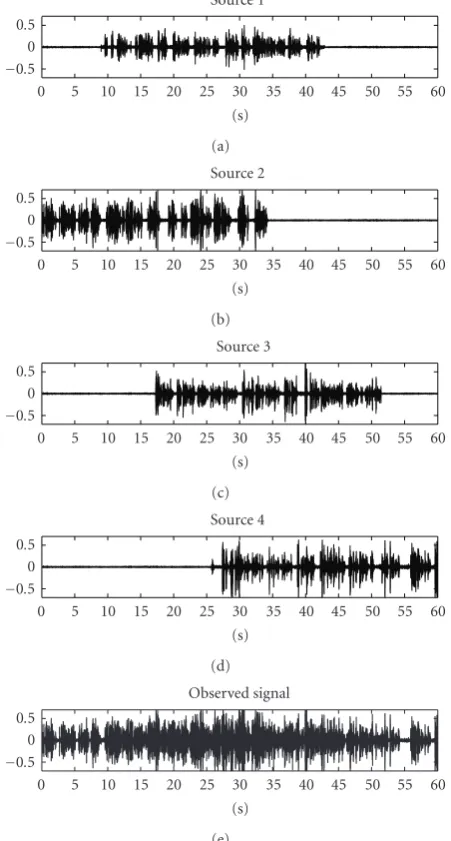
Figure 4shows the time domain plots of the speech sig-nals and the observed signal at the 4th microphone. The length of the speaker speech signals is 35 seconds and the speech signals were recorded separately for the evaluations. Note that the recording was made from the actual human speakers and the speech signals occurred at different times
−0.5 0 0.5
Source 1
0 5 10 15 20 25 30 35 40 45 50 55 60 (s)
(a)
−0.5 0 0.5
Source 2
0 5 10 15 20 25 30 35 40 45 50 55 60 (s)
(b)
−0.5 0 0.5
Source 3
0 5 10 15 20 25 30 35 40 45 50 55 60 (s)
(c)
−0.5 0 0.5
Source 4
0 5 10 15 20 25 30 35 40 45 50 55 60 (s)
(d)
−0.5 0 0.5
Observed signal
0 5 10 15 20 25 30 35 40 45 50 55 60 (s)
(e)
Figure4: Time domain plots of the original sources and the ob-served signal at the 4th microphone.
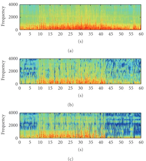
and overlaped each other. The overlapping is used to sim-ulate simultaneous conversation between the speakers. The corresponding spectrogram plots of the speech signals and the observed signal at the 4th microphone are depicted in
Figure 5.
The observed signals are decomposed intoM =64 sub-bands by using a uniform oversampled analysis filterbank. In this case, a oversampling factor of two is chosen to reduce the aliasing effects between adjacent subbands [16]. The perfor-mance of the proposed beamformer is measured in terms of the interference suppression (IS) level, defined as
IS=10 log10 # $π
−πPin,n(ω)dω $π
−πPout,n(ω)dω %
−10 log10Cd
0 2000 4000
Speech 1
Fre
q
u
en
cy
0 5 10 15 20 25 30 35 40 45 50 55 60 (s)
(a)
0 2000 4000
Speech 2
Fre
q
u
en
cy
0 5 10 15 20 25 30 35 40 45 50 55 60 (s)
(b)
0 2000 4000
Speech 3
Fre
q
u
en
cy
0 5 10 15 20 25 30 35 40 45 50 55 60 (s)
(c)
0 2000 4000
Speech 4
Fre
q
u
en
cy
0 5 10 15 20 25 30 35 40 45 50 55 60 (s)
(d)
0 2000 4000
Observed signal
Fre
q
u
en
cy
0 5 10 15 20 25 30 35 40 45 50 55 60 (s)
(e)
Figure5: Spectrograms of the original sources and the observed signal at the 4th microphone.
wherePin,n(ω) andPout,n(ω) are the spectral power estimates of the reference microphone observation and the output, re-spectively, when the interferences are active alone andCdis a constant to normalize the desired source’s gain. The perfor-mance is also given in terms of the source distortion measure (SD), defined as
SD=10 log10 #
1 2π
&π
−π #C1
d %
Pin,s(ω)−Pout,s(ω) dω
% ,
(36)
wherePin,s(ω) andPout,s(ω) are the spectral power estimates of the reference microphone observation and the output, re-spectively, when the desired source is active alone. The source distortion is the mean output spectral power deviation from the observed single sensor spectral power. Ideally, the distor-tion is zero.
−0.5 0 0.5
0 5 10 15 20 25 30 35 40 45 50 55 60 (s)
(a)
−0.5 0 0.5
0 5 10 15 20 25 30 35 40 45 50 55 60 (s)
Source is inactive
Source is inactive Source is active
(b)
−0.5 0 0.5
0 5 10 15 20 25 30 35 40 45 50 55 60 (s)
Source is inactive
Source is inactive Source is active
(c)
Figure6: Source 1 is the desired source: time domain plots of out-puts from (a) the fixed multiobjective optimal beamformer, (b) the postfilter with power spectral estimation using inner product and (c) the postfilter with power spectral estimation using joint diago-nalization.
−0.5 0 0.5
0 5 10 15 20 25 30 35 40 45 50 55 60 (s)
(a)
−0.5 0 0.5
0 5 10 15 20 25 30 35 40 45 50 55 60 (s)
Source is active Source is inactive
(b)
−0.5 0 0.5
0 5 10 15 20 25 30 35 40 45 50 55 60 (s)
Source is active Source is inactive
(c)
0 2000 4000
Fre
q
u
en
cy
0 5 10 15 20 25 30 35 40 45 50 55 60 (s)
(a)
0 2000 4000
Fre
q
u
en
cy
0 5 10 15 20 25 30 35 40 45 50 55 60 (s)
(b)
0 2000 4000
Fre
q
u
en
cy
0 5 10 15 20 25 30 35 40 45 50 55 60 (s)
(c)
Figure8: Source 1 is the desired source: spectrograms of outputs from (a) the fixed multiobjective optimal beamformer, (b) the post-filter with power spectral estimation using an inner product, and (c) the postfilter with power spectral estimation using joint diago-nalization.
Here, one speaker is viewed as the desired signal while others are undesired or interference signals. Obviously, the suppression levels for each undesired source are different de-pending on the spatial differences between its location and the location of the desired source. However, we consider all the undesired signals as one interference signal for evaluating the IS level for the proposed methods.
The proposed beamformers are employed to enhance a desired speech signal. Figures6and8show, respectively, the time domain and the spectrogram plots of (a) the fixed mul-tiobjective optimal beamformer, (b) the postfilter with PSD estimation using an inner product, and (c) the postfilter with PSD estimation using joint diagonalization, with the desired source chosen as the 1st source. Also, the time domain and the spectrogram plots of the output for the 2nd source are illustrated in Figures7and9, respectively.
As the suppression and distortion levels are different for the active and inactive periods of the desired source, these two cases are analyzed separately.
6.1. Active time of the desired source
Evaluations are obtained for the periods in which the de-sired source is active. For example, the periods [9 seconds, 42 seconds] and [0 second,34 seconds] are considered as the active time for the 1st and the 2nd sources, respectively. Also, Figures6and7show the active time for the corresponding
desired sources. The active periods are viewed as “source is active.”
The desired source is chosen as one of the four speech signals.Table 1shows the IS and the SD levels in the output of the delay and sum beamformer, the multiobjective opti-mal beamformer, the postfilter with PSD estimation using an inner product, and the postfilter with PSD estimation using joint diagonalization. The delay and sum beamformer forms a beam towards a specified direction by matching the de-lay such that signals from that direction will be reinforced (summed together with matching delay).
The IS level for the delay and sum beamformer ranges from 0.3 to 1.3 dB depending on the desired source posi-tion. The IS level for the multiobjective optimal beamformer ranges from 5 to 6.57 dB depending on the desired source position. The results show that the multiobjective optimal beamformer achieves a significant improvement in the IS levels over the delay and sum beamformer. The postfilters improve further the IS levels of the multiobjective optimal beamfomer outputs. More specifically, the postfilter with PSD estimation using an inner product improves approxi-mately 3 dB in IS level over the fixed multiobjective opti-mal beamformer for all the desired sources. The postfilter with PSD estimation using joint diagonalization improves approximately 2.5 dB in IS level for all the desired sources.
The speakers 1 and 4 have slightly better IS than the other two speakers. This is due to the fact that those speakers’ po-sitions are more spatially separated when compared to the other positions. From simulation results, the postfilter with PSD estimation using inner product has a slightly higher IS level than the one using joint diagonalization. On the other hand, the postfilter using joint diagonalization has a slightly lower SD than the one with inner product. In general, all the outputs have low SD levels, leading to low distortion of the desired source.
6.2. Inactive time of the desired source
Evaluations are also obtained for the periods in which the desired source is inactive. For example, the time periods [0 second, 9 seconds] and [42 seconds, 60 seconds] are inac-tive periods for the 1st source, (seeFigure 6). Thus, evalu-ation is performed for the combining outputs of both peri-ods. Also, the time period [34 seconds, 60 seconds] is inactive period for the 2nd source (seeFigure 7). In Figures6and7, the inactive periods for the corresponding desired sources are viewed as “source is inactive.” In addition, the signal to inter-ference ratio (SIR) is zero in the inactive source periods and there is only an IS measure for the evaluation.
Table1: Desired source is active: IS and SD levels of delay and sum beamformer (DLSB) output, fixed multiobjective optimal beamformer (FMOB) output, the postfilter with power spectral estimation using an inner product (PF & IPT), and the postfilter with power spectral estimation using joint diagonalization (PF & JDG).
Desired source
DLSB FMOB PF & IPT PF & JDG
IS SD IS SD IS SD IS SD
dB dB dB dB dB dB dB dB
1 1.3 −37.4 6.8 −29.2 9.5 −27.9 9.2 −28.2
2 0.3 −35.8 5.7 −26.6 9.1 −25.4 8.0 −26.0
3 0.7 −37.4 5.0 −28.2 7.9 −26.3 7.1 −26.9
4 0.8 −37 6.3 −26 8.9 −25.0 8.6 −25.5
Table2: Desired source is nonactive: IS levels for the outputs of de-lay and sum beamformer (DLSB), the fixed multiobjective optimal beamformer (FMOB), postfilter with power spectral estimation us-ing inner product (PF & IPT), and postfilter with power spectral estimation using joint diagonalization (PF & JDG).
Desired DLSB FMOB PF & IPT PF & JDG
source IS (dB) IS (dB) IS (dB) IS (dB)
1 1.3 7.2 17.7 17.1
2 0.3 6.7 17.2 16.3
3 0.7 5.4 15.9 14.5
4 0.8 6.8 17.1 16.9
0 2000 4000
Fre
q
u
en
cy
0 5 10 15 20 25 30 35 40 45 50 55 60 (s)
(a)
0 2000 4000
Fre
q
u
en
cy
0 5 10 15 20 25 30 35 40 45 50 55 60 (s)
(b)
0 2000 4000
Fre
q
u
en
cy
0 5 10 15 20 25 30 35 40 45 50 55 60 (s)
(c)
Figure9: Source 2 is the desired source: spectrograms of outputs from (a) the fixed multiobjective optimal beamformer, (b) the post-filter with power spectral estimation using an inner product, and (c) the postfilter with power spectral estimation using joint diago-nalization.
where the desired source is active. More specifically, the post-filter using an inner product improves approximately 10 dB over the fixed multiobjective optimal beamformer output for all desired sources. Similarly, the postfilter with PSD esti-mation using joint diagonalization improves approximately 9 dB for all the desired sources.
Similar to the case where the desired source is active, bet-ter IS levels are obtained for the 1st and the 4th speakers. Also, the postfilter with PSD estimation using an inner prod-uct has a slightly higher suppression level than the one using joint diagonalization.
From the simulation results, the postfilter with spectral estimation using an inner product has a slightly higher in-terference suppression level than the postfilter with spectral estimation using the joint diagonalization. This also comes with a higher computational complexity as the number of real multiplications required for each frequency bin by the first estimation method is higher than the second method, for example, 4(2L2+ 1) versus 4L2, (see Sections5.1and5.2). A limitation of the proposed methods is that calibration is required for the spatial correlation matrix estimation. Fur-ther work is required to investigate the near-field estimation models of the spatial correlation matrix with on-time spatial information update.
7. CONCLUSIONS
In this paper, a two-stage beamformer structure is proposed for speech enhancement in a multispeaker environment. In the first stage, a fixed multiobjective optimal beamformer is designed to spatially extract the desired source. In the second stage, a postfilter technique is used to further enhance the ex-traction process. Two different multichannel power spectral estimation methods have been proposed and evaluated. Both methods are capable of estimating the desired source PSD in a multispeaker environment. Evaluations in a real environ-ment show that both methods have similar suppression ca-pability and comparable distortion levels. The postfilter with spectral estimation using inner product has a slightly higher suppression level than the method using joint diagonaliza-tion with a higher computadiagonaliza-tional complexity.
ACKNOWLEDGMENTS
was sponsored by National ICT Australia (NICTA). NICTA is funded through the Australian Government’s Backing Aus-tralia’s Ability initiative, in part through Australian Research Council.
REFERENCES
[1] J. Benesty, S. Makino, and J. Chen, Eds.,Speech Enhancement, Springer, Berlin, Germany, 2005.
[2] M. Brandstein and D. Ward, Eds.,Microphone Arrays: Signal Processing Techniques and Applications, Springer, Berlin, Ger-many, 2001.
[3] S. Nordebo, I. Claesson, and S. Nordholm, “Adaptive beam-forming: spatial filter designed blocking matrix,”IEEE Journal of Oceanic Engineering, vol. 19, no. 4, pp. 583–590, 1994. [4] S. Doclo and M. Moonen, “GSVD-based optimal filtering
for single and multimicrophone speech enhancement,”IEEE Transactions on Signal Processing, vol. 50, no. 9, pp. 2230–2244, 2002.
[5] N. Grbi´c, S. Nordholm, and A. Cantoni, “Optimal FIR sub-band beamforming for speech enhancement in multipath en-vironments,”IEEE Signal Processing Letters, vol. 10, no. 11, pp. 335–338, 2003.
[6] S. Haykin,Adaptive Filter Theory, Prentice Hall, Upper Saddle River, NJ, USA, 4th edition, 2001.
[7] H. Q. Dam, S. Y. Low, S. Nordholm, and H. H. Dam, “Adaptive microphone array with noise statistics updates,” in Proceed-ings of the International Symposium on Circuits and Systems (ISCAS ’04), vol. 3, pp. 433–436, Vancouver, British Columbia, Canada, May 2004.
[8] S. Boll, “Suppression of acoustic noise in speech using spec-tral subtraction,”IEEE Transactions on Acoustics, Speech, and Signal Processing, vol. 27, no. 2, pp. 113–120, 1979.
[9] B. L. Sim, Y. C. Tong, J. S. Chang, and C. T. Tan, “A parametric formulation of the generalized spectral subtraction method,”
IEEE Transactions on Speech and Audio Processing, vol. 6, no. 4, pp. 328–337, 1998.
[10] H. Gustafsson, S. Nordholm, and I. Claesson, “Spectral sub-traction using reduced delay convolution and adaptive averag-ing,”IEEE Transactions on Speech and Audio Processing, vol. 9, no. 8, pp. 799–807, 2001.
[11] R. Zelinski, “A microphone array with adaptive post-filtering for noise reduction in reverberant rooms,” inProceedings of the International Conference on Acoustics, Speech, and Signal Processing (ICASSP ’88), vol. 5, pp. 2578–2581, New York, NY, USA, April 1988.
[12] I. A. McCowan and H. Bourlard, “Microphone array post-filter based on noise field coherence,”IEEE Transactions on Speech and Audio Processing, vol. 11, no. 6, pp. 709–716, 2003. [13] I. Cohen, “Multichannel post-filtering in nonstationary noise environments,”IEEE Transactions on Signal Processing, vol. 52, no. 5, pp. 1149–1160, 2004.
[14] Y. Huang, J. Benesty, and J. Chen, “Separation and dereverber-ation of speech signals with multiple microphones,” inSpeech Enhancement, chapter 12, pp. 271–298, Springer, Berlin, Ger-many, 2005.
[15] Y. Cao, S. Sridharan, and M. Moody, “Speech enhancement iby simulation of cocktail party effect with neural network controlled iterative filter,” inProceedings of the 4th Interna-tional Symposium on Signal Processing and Its Applications (ISSPA ’96), vol. 2, pp. 541–544, Gold Cost, Australia, August 1996.
[16] J. M. de Haan, N. Grbi´c, I. Claesson, and S. Nordholm, “De-sign of oversampled uniform DFT filter banks with delay
spec-ification using quadratic optimization,” inProceedings of the IEEE Interntional Conference on Acoustics, Speech, and Sig-nal Processing (ICASSP ’01), vol. 6, pp. 3633–3636, Salt Lake, Utah, USA, May 2001.
[17] H. Q. Dam, S. Nordholm, H. H. Dam, and S. Y. Low, “Maxi-mum likelihood estimation and Cramer-Rao lower bounds for the multichannel spectral evaluation in hands-free communi-cation,” inProceedings of Asia-Pacific Conference on Commu-nications (APCC ’05), pp. 961–964, Perth, Australia, October 2005.
[18] H. Q. Dam, S. Nordholm, H. H. Dam, and S. Y. Low, “Post-filtering with multichannel power spectral estimation using joint diagonalization in multi-speaker environments,” inProceedings of Asia-Pacific Conference on Communications (APCC ’06), pp. 1–5, Busan, Korea, August 2006.
[19] S. Nordholm, I. Claesson, and M. Dahl, “Adaptive microphone array employing calibration signals: an analytical evaluation,”
IEEE Transactions on Speech and Audio Processing, vol. 7, no. 3, pp. 241–252, 1999.
[20] G. L. Fudge and D. A. Linebarger, “Calibrated generalized side-lobe canceller for wideband beamforming,”IEEE Transactions on Signal Processing, vol. 42, no. 10, pp. 2871–2875, 1994. [21] J. M. Sachar, H. F. Silverman, and W. R. Patterson III,
“Posi-tion calibra“Posi-tion of large-aperture microphone arrays,” in Pro-ceedings of IEEE International Conference on Acoustics, Speech and Signal Processing (ICASSP ’02), vol. 2, pp. 1797–1800, Or-lando, Fla, USA, May 2002.
[22] G. Strang,Linear Algebra and Its Applications, Academic Press, New York, NY, USA, 1976.