Optimization of Multirate Polyphase Decimator
using MCM and Digit Serial Architecture
Rajendra M. Rewatkar
#1, Dr. Sanjay L. Badjate
#2#1Datta Meghe Institute of Engineering Technology and
Research, Sawangi (Meghe), Wardha-442001 India.
#2Department of Electronics and communication Engineering
S.B. Jain Institute of Engineering, Management and Research, Nagpur-India
Abstract:A Paper Presents Optimization Technique of Multirate
Polyphase Decimator. Many efficient algorithms and architectures developed for the design of low complexity, bit parallel Multiple Constant Multiplications operation which dominates the complexity of DSP systems. However, major drawbacks of present approaches are either two costly or not efficient enough. On the other hand, MCM and digit-serial architecture offer alternative low complexity designs, since digit-serial operators occupy less area and are independent of the data word length. Multiple Constant Multiplications is efficient way to reduce the number of addition and subtraction in FIR filter implementation. The proposed device Multirate Polyphase decimator is designed by different techniques to reduced circuit complexity. Adders, multipliers and latches are reduced by different logic due to which power and area in system is reduced at great extend. The simulation of parameters is analyzed by using synopsis 45 nm and Xilinx. Experimental results have shown the efficiency of the proposed technique and the analysis of different architecture. Recent advances in mobile computing and communication applications demand low power and high speed VLSI DSP systems. The digital filters employed in mobile systems must be higher order and realized to consume less power at high speed. This Multirate design methodology is systematic and applicable to many problems.
Keywords: VLSI-Very large scale integrated circuit, RTL-Register
transfer logic, VHDL-Very high speed hardware description language, DSP-Digital Signal Processing, FIR Finite impulse response, FPGA: Field Programmable gate array, MCM-Multiple Constant Multiplication
I.INTRODUCTION:
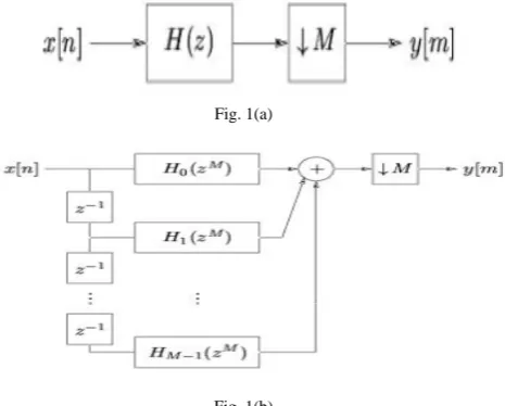
Many decimation filters implement a Polyphase structure. The Polyphase structure is just another efficient filter for decimation like the direct form decimator, where the filter output is computed at the decimated rate. FIR filters are widely applied in multi standard wireless communications. One of the most important operations in DSP is finite impulse response filtering. The FIR filter performs the weighted summations of input sequences and is widely used in mobile communication systems for variety of tasks such as channelization, channel equalization, pulse shaping and matched filtering due to their properties of linear phase and absolute stability [2].
A signal processing system that filters the data and has an output data rate is different than the input data rate called
Multirate filter. The ratio of the output data rate to the input data rate is known as the Multirate factor. In decimation and Interpolation Multirate filters, the normalized transition
bandwidth inversely relates to the decimation factor M and
the interpolation factor L. The order of a decimation or
interpolation filter increases as M or L [21].we can use
multistage Multirate filters to simplify Multirate filters that have large sampling frequency conversion factors. Polyphase is a way of doing sampling rate conversion that leads to very efficient implementations. Sampling rate reduction is required for efficient transmission, and a sampling rate increase is required for the regeneration of the speech. The processes of sampling rate reduction called decimation. It can be efficiently implemented using finite impulse response digital filters [4]. It is found that efficient implementations of low pass FIR filters could be obtained by a process of first reducing the sampling rate, filtering, and then increasing the sampling rate back to the original frequency. The process of sampling rate reduction in Multirate Polyphase Decimator is shown in fig.1 (a)-(b)-(c).
Fig. 1(a)
Fig.1(c) Polyphase decimator
FIR based filtering is advantageous in many digital signal processing systems due to the possibility of exact linear phase and freedom of stability problems. However, the major drawback versus IIR filters is the high cost of the implementation as well as high power consumption. Recently, several schemes have been proposed to reduce the arithmetic complexity of both FIR and IIR structures, e.g., sub expression sharing, multiple-constant multiplication [3] [5], and multiplier blocks. Special low sensitivity filter structures are another route to reduce the FIR filter complexity. Further, frequency masking techniques and Multirate structures together with the design methods can be used to implement low complexity and high speed FIR filters. In this paper, we discuss the design of a Polyphase decimation of the sample frequency [7].
II.MULTIRATE POLYPHASE DECIMATOR DESIGN
METHODOLOGY:
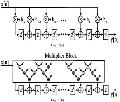
Low power, High performance is two most important criteria for many signal processing system designs. Particularly, real time multimedia applications; there have been many approaches to achieve this goal at different implementation level. We have introduced a new architecture based low power and high performance design technique. i.e. Multirate approach and combine it along with DSP techniques such as shifting, carry look ahead and folding etc. to design several DSP blocks like FIR/IIR and Polyphase filtering. In this, we design Multirate Polyphase Decimator in direct form, transposed form, using MCM and Digit serial architecture.The development of efficient algorithms has to a high extent been motivated by the use of MCM blocks in FIR filters. For direct transposed form FIR filters the input is multiplied with the filter coefficients as shown in Fig. 2(a)-(b), where the MCM block is marked with a dashed box. Using transposition, direct form FIR filter is obtained, where the sum-of-product computation is marked with a dashed box[13]. Hence, MCM is also efficient for sum-of-product computations.
Fig. 2(a)
Fig.2 (b)
The digit-serial MCM operation in shift-adds architecture consists of digit-serial addition and subtraction operations, and D flip-flops for the shift operations, as opposed to the bit-parallel MCM operation, where shifts are free in terms of hardware. The high-level algorithm aims to find a solution with the fewest number of additions, subtractions, and shift operations. The complexity of the resulting realization will be depending on three factors. First, the size, numbers, and type of MCM blocks. Second, the number of delay elements, and, finally the number of structural additions, i.e., the additions that are not part of the MCM block (additions outside of the dashed box in Fig. 2 (a)). Here, we focus the discussion on Polyphase decomposed decimation filters, but identical results can be derived for the filter bank case [12].
Another concept can be used to optimize the parameters is multiplication using shifts, additions, and subtractions realization without general multipliers. The number of additions and subtractions can be significantly reduced by using common partial results [1]. As additions and
subtractions have similar complexity as an example,
consider the constant multiplications 29x and 43x. Observe from Figure 3 & 4 that the sharing of partial products 3x and 5x reduces the number of operations from 6 to 4.
Fig.4 The digit serial operation when d is equal to 3: (a) Addition operation (b)Subtraction Operation(c)Left shift by 2 times (d)Left shift by 4 times
The direct form is generally preferred because of its higher performance and power efficiency. The problem of designing Polyphase decimator has received a great attention due to large number of multiplications [7]. This implementation must satisfy the enforced sampling rate constraints of the real time DSP applications and must require less space and power consumption. Present works have focused on design of Multirate Polyphase decimator by filters, data generator latches and adder. As the coefficients of an application specific filter are constant, the decomposition is more efficient than employing multipliers. The complexity of FIR filters in this case is dominated by the number of additions and multiplications [10]. The multiplier block of the digital FIR filter in its direct form is implemented in the design so that significant impact on the complexity and performance of the design will be improved. Also, Polyphase filter is designed using MCM and digit serial adders which overcome problem of complexity, design performance and producing very low area [9][17]. Authors have used the different techniques to reduce the complexity in the design and implemented the Polyphase filter on FPGA platform using cyclone-II device. Finite impulse response filters are of great importance in digital signal processing systems since their characteristics in linear phase and feed forward implementations make them very useful for building stable high performance filters. In this, Polyphase decimator filter with a factor of 18 is designed using three cascaded filters. The impulse response is obtained by convolution of three vectors with 18 ones in each, The trade-off between additions and delay elements is circuit and technology dependent, and, hence, should be evaluated on the circuit level.
Another method which requires moderate sample rate, these systems may be ineffective. Bit serial system will be too slow and bit parallel system is faster. Therefore, digit serial systems have become attractive for digital designers in the recent years. These systems process multiple bits of the
input word, referred to as the digit size, in one clock cycle. For a digit size of unity, the system reduces to a bit serial, and for a digit size equal to the word length, the system reduces to a bit parallel system. Most of the DSP computations involve the use of multiply accumulate operations. Therefore, the design of fast and efficient multipliers is imperative. The bit serial systems, which process one bit of the input sample in one clock cycle, are area efficient and ideal for low speed applications. On the other hand, bit parallel systems which process one whole word of the input sample in one clock cycle, are ideal for high speed applications[4][8].
III.RESULT:
POLYPHASE DECIMATOR:
I] Following figure 5(a) – (d) shows direct form of Polyphase decimator which uses latches in direct form, this system is very efficient because it required very less power dissipation and maintaining higher speed. But this design consumed more area.
Fig. 5(a) RTL view of Polyphase decimator in direct form
Fig. 5(b) Internal structure of filter in direct form
cl
k rst c(31:0)
b(31:0) h0( 7:0 ) h12 (7 :0 ) h15 (7 :0 ) h3( 7:0 ) h6( 7:0 ) h9( 7:0 ) x(7:0) U1 ddfb0 cl
k rst c(31:0)
b(31:0) h1( 7:0 ) h10 (7 :0 ) h13 (7 :0 ) h16 (7 :0 ) h4( 7:0 ) h7( 7:0 ) x(7:0) U2 ddfb1 cl
k rst c(31:0)
b(31:0) h11 (7 :0 ) h14 (7 :0 ) h17 (7 :0 ) h2( 7:0 ) h5( 7:0 ) h8( 7:0 ) x(7:0) U3 ddfb2 clkclkb0 rstclkb1 clkb2 xout(7:0) U4 datagen_ddf1 eresult(31:0) h0(7:0) h1(7:0) h2(7:0) h3(7:0) h4(7:0) h5(7:0) h6(7:0) h7(7:0) h8(7:0) h9(7:0) h10(7:0) h11(7:0) h12(7:0) h13(7:0) h14(7:0) h15(7:0) h16(7:0) h17(7:0) U5 con_coeff clk rst
d(31:0)cl q(31:0) krst U7
latch32
d(31:0)clkrsq(31:0)
t U8 latch32 a(31:0) d(31:0) b(31:0) c(31:0) U6 adder3231 c0(31:0) x(7:0) h12(7:0) h9(7:0) h15(7:0) b(31:0) a (7: 0) c( 1 3 :0 ) b( 7: 0) U4 m u lt i1 6 a (7: 0) c( 1 3 :0 ) b( 7: 0) U5 m u lt i1 6 a (7: 0) c( 1 3 :0 ) b( 7: 0) U6 m u lt i1 6 a (7: 0) c( 1 3 :0 ) b( 7: 0) U3 m u lt i1 6 a (7: 0) c( 1 3 :0 ) b( 7: 0) U1 m u lt i1 6 a (7: 0) c( 1 3 :0 ) b( 7: 0) U2 m u lt i1 6 BUS7626(15:0) BUS8689(32:0) a( 1 3 :0 ) c(31:0) b(31:0) U31 adder1431 a( 1 3 :0 ) c(31:0) b(31:0) U32 adder1431 a( 1 3 :0 ) c(31:0) b(31:0) U33 adder1431 a( 1 3: 0 ) c(31:0) b(31:0) U34 adder1431 a( 1 3 :0 ) c(31:0) b(31:0) U35 adder1431 a( 1 3 :0 ) c(31:0) b(31:0) U26 adder1431 d(7:0) q(7:0) cl
krst U37
latch
d(7:0) q(7:0)
cl
krst U38
latch
d(7:0) q(7:0)
cl
krst U39
latch
d(7:0) q(7:0)
cl
krst U40
latch
d(7:0) q(7:0)
cl
krst U41
latch
d(7:0) q(7:0)
cl
krst U42
latch
rst clk
h0(7:0) h3(7:0) h6(7:0)
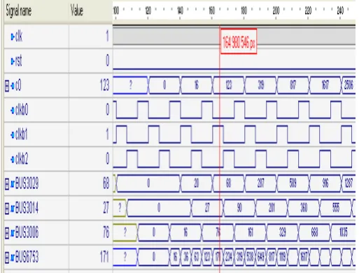
Fig.5(c) Design waveform
Fig.5(d) Design vision schematic of Polyphase Decimator in Direct form
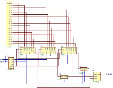
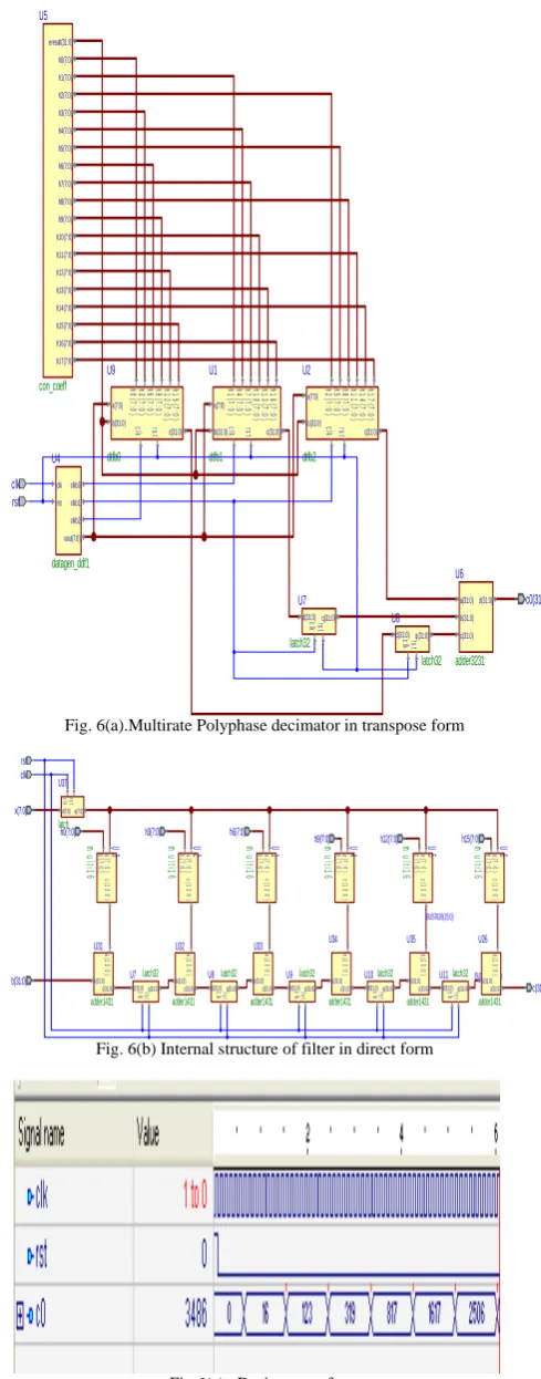
II] Following figure 6(a)-(d) shows transpose form of Polyphase decimator. This design uses latches in transpose form. Therefore, this system required less area than direct form by maintaining moderate power dissipation and speed.
Fig. 6(a).Multirate Polyphase decimator in transpose form
Fig. 6(b) Internal structure of filter in direct form
Fig.6(c) Design waveform clk clkb0
rst clkb1 clkb2 xout(7:0)
U4
datagen_ddf1
eresult(31:0) h0(7:0) h1(7:0) h2(7:0) h3(7:0) h4(7:0) h5(7:0) h6(7:0) h7(7:0) h8(7:0) h9(7:0) h10(7:0) h11(7:0) h12(7:0) h13(7:0) h14(7:0) h15(7:0) h16(7:0) h17(7:0)
U5
con_coeff
clk rst
d(31:0) q(31:0)cl k rst
U7
latch32 d(31:0) q(31:0)clkrst
U8
latch32
a(31:0) d(31:0) b(31:0) c(31:0)
U6
adder3231
c0(31:0)
cl
k rst c(31:0) b(31:0)
h0
(7
:0
)
h
12(
7
:0)
h
15(
7
:0)
h3
(7
:0
)
h6
(7
:0
)
h9
(7
:0
)
x(7:0)
U9
dtfb0
cl
k rst c(31:0) b(31:0)
h1
(7
:0
)
h
10(
7
:0)
h
13(
7
:0)
h
16(
7
:0)
h4
(7
:0
)
h7
(7
:0
)
x(7:0)
U1
dtfb1
cl
k rst c(31:0) b(31:0)
h
11(
7
:0)
h
14(
7
:0)
h
17(
7
:0)
h2
(7
:0
)
h5
(7
:0
)
h8
(7
:0
)
x(7:0)
U2
dtfb2
x(7:0)
h12(7:0)
h9(7:0) h15(7:0)
b(31:0)
a
(7:
0)
c(
1
3
:0
)
b
(7:
0)
U4
m
u
lt
i1
6
a
(7:
0)
c(
1
3
:0
)
b
(7:
0)
U5
m
u
lt
i1
6
a
(7:
0)
c(
1
3
:0
)
b
(7:
0)
U6
m
u
lt
i1
6
a
(7:
0)
c(
1
3
:0
)
b
(7:
0)
U3
m
u
lt
i1
6
a
(7:
0)
c(
1
3
:0
)
b
(7:
0)
U1
m
u
lt
i1
6
a
(7:
0)
c(
1
3
:0
)
b
(7:
0)
U2
m
u
lt
i1
6
BUS7626(15:0)
BUS8689(32:0)
a(
1
3:
0
)
c(31:0) b(31:0)
U31
adder1431
a(
1
3:
0
)
c(31:0) b(31:0)
U32
adder1431
a(
1
3:
0
)
c(31:0) b(31:0)
U33
adder1431
a(
1
3:
0
)
c(31:0) b(31:0)
U34
adder1431
a(
1
3:
0
)
c(31:0) b(31:0)
U35
adder1431
a(
1
3:
0
)
c(31:0) b(31:0)
U26
adder1431 rst
clk
h0(7:0) h3(7:0) h6(7:0)
c(31:0)
d(31:0) q(31:0)cl krst
U7latch32
d(31:0) q(31:0)cl krst
U8latch32
d(31:0) q(31:0)cl krst
U9latch32
d(31:0) q(31:0)cl krst
U10latch32
d(31:0) q(31:0)cl krst
U11latch32
d(7:0) q(7:0)
cl
krst
U37
Fig.6(d) Design vision schematic of Polyphase Decimator in transpose form
III] Authors efforts are directed towards reduction of area at great extend succeeded by using MCM of Multirate
Polyphase decimator. This design consumed moderate power.
Fig. 7(a).Multirate Polyphase decimator using MCM
Fig. 7(b) Internal structure of filter in Direct form
Fig.7(c) Design waveform
Fig.7(d) Design vision schematic of polyphase decimator using MCM
clk clkb0 rst clkb1 clkb2 xout(7:0) U4
datagen_ddf1
clk rst
d(31:0) q(31:0)cl krst U7latch32
d(31:0) q(31:0)cl k rst U8
latch32
a(31:0) d(31:0) b(31:0) c(31:0) U6
adder3231
c0(31:0)
cl
k
c(31:0)
rs
t
b(31:0) x(7:0) U3dmcmb0
cl
k
c(31:0)
rs
t
b(31:0) x(7:0) U10dmcmb1
cl
k
c(31:0)
rs
t
b(31:0) x(7:0) U11dmcmb2
Y(31:0) U1
contout321
x(7:0)
b(31:0) BUS8689(32:0)
a(
1
3:
0
)
c(31:0) b(31:0)
U31
adder1431
a(
1
3:
0
)
c(31:0) b(31:0)
U32
adder1431
a(
1
3:
0
)
c(31:0) b(31:0)
U33
adder1431
a(
1
3:
0
)
c(31:0) b(31:0)
U34
adder1431
a(
1
3:
0
)
c(31:0) b(31:0)
U35
adder1431
a(
1
3:
0
)
c(31:0) b(31:0)
U26
adder1431
rst clk
c(31:0)
d(31:0) q(31:0)cl krst
U7latch32
d(31:0) q(31:0)cl krst
U8latch32
d(31:0) q(31:0)cl krst
U9latch32
d(31:0) q(31:0)cl krst
U10latch32
d(7:0) q(7:0)
cl
krst
d(31:0) q(31:0)cl krst
U11latch32
U37
latch
a(
7
:0
)
y(
1
3
:0
)
U7
5
mu
lh
0
a(
7
:0
)
y(
1
3
:0
)
U7
8
mu
lh
3
a(
7
:0
)
y(
1
3
:0
)
U7
6
mu
lh
4
a(
7
:0
)
y(
1
3
:0
)
U7
7
mu
lh
1
a(
7
:0
)
y(
1
3
:0
)
U7
9
mu
lh
2
a(
7
:0
)
y(
1
3
:0
)
U1
mu
lb
IV] Following figure 8(a)-(d) shows transpose form of Polyphase decimator which uses MCM & digit serial adder. This system required less area and maintaining higher speed.
Fig. 8(a)Multirate Polyphase decimator using MCM & Digit Serial architecture
Fig.8(b) Internal structure of filter in direct form
Fig.8(c) Design waveform
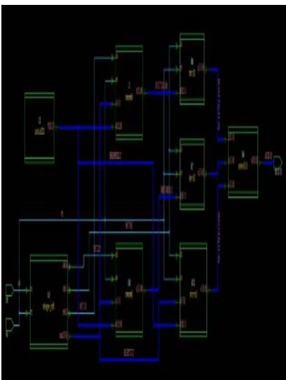
Fig.8(d) Design vision schematic of polyphase decimator in mcmds
The Multirate Polyphase decimator is implemented on FPGA cyclone –II device which shown complete setup of the design as follows cl k c(31:0) cl ksh lo a d rs
tsel_sel
su m co u t b(31:0) se lb its( 3 :0 ) x(7:0) U1dmcmdsb0 cl k c(31:0) cl ksh lo a d rs
tsel_sel
su m co u t b(31:0) se lb its( 3 :0 ) x(7:0) U2dmcmdsb1 cl k c(31:0) cl ksh lo a d rs
tsel_sel
su m co u t b(31:0) se lb its( 3 :0 ) x(7:0) U3dmcmdsb2 rst clk cl k adderclk rst clksh load sel sel_sumcount selbits(3:0) U54 adderfsm1 a y b sel U38 mux211 a(31:0) d(31:0) b(31:0) c(31:0) U6 adder3231 c0(31:0) Y(31:0) U9 contout321 clk clkb0 rst clkb1 clkb2 U5clkseq1 clk cl k0 rst rs t0 selbit(3:0) se lb it0 (3 :0 ) selsum_cout s e ls um _c o ut 0 sel se l0 load lo a d 0 clksh cl ksh 0 ck0 cl k1 ck1 rs t1 ck2 se lb it1 (3 :0 ) s e ls um _c o ut 1 se l1 lo a d 1 cl ksh 1 cl
k2rst2
se lb it2 (3 :0 ) s e ls um _c o ut 2 se l2 lo a d 2 cl ksh 2 U4 demux31_dec1 clk sout(7:0) rs t U8datadumpgen2 d(31:0) q(31:0) cl
k rst
U37latch32 x(7:0) c(31 a( 7 :0 ) y( 1 3 :0 ) a( 7 :0 ) y( 1 3 :0 ) a( 7 :0 ) y( 1 3 :0 ) a( 7 :0 ) y( 1 3 :0 ) a( 7 :0 ) y( 1 3 :0 ) U7 5 mu lh 0 U7 8 mu lh 3 U7 6 mu lh 4 U7 7 mu lh 1 U7 9 mu lh 2 a( 7 :0 ) y( 1 3 :0 ) U1 mu lb y1 b(31:0) cl k dout(31:0) cl k sh lo a d rs
t sel
se l_ su m c o u t O1(31:0) O2 (1 3 :0 ) se lb its (3 :0 ) U18 ad der m o di 1 cl k dout(31:0) cl k sh lo a d rs
t sel
se l_ su m c o u t O1(31:0) O2 (1 3 :0 ) se lb its (3 :0 ) U19 ad der m o di 1 cl k dout(31:0) cl k sh lo a d rs
t sel
se l_ su m c o u t O1(31:0) O2 (1 3 :0 ) se lb its (3 :0 ) U20 ad der m o di 1 cl k dout(31:0) cl k sh lo a d rs
t sel
se l_ su m c o u t O1(31:0) O2 (1 3 :0 ) se lb its (3 :0 ) U21 ad der m o di 1 cl k dout(31:0) cl k sh lo a d rs
t sel
se l_ su m c o u t O1(31:0) O2 (1 3 :0 ) se lb its (3 :0 ) U22 ad der m o di 1 cl k dout(31:0) cl k sh lo a d rs
t sel
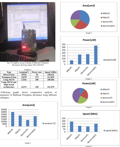
Fig. 9 Complete set up of design of Multirate Polyphase Decimator showing output 100111001010
TABLE 1
Type Area[um2] Power (uw) Speed (MHz)
Direct Form 29741 70 190.621
Transpose Form 22579 173 111.025
Using MCM 13256 180 100.604
Using MCM and Digit Serial
architecture 21271 330 151.579
Following graphs shown comparative analysis of parameters of Multirate Polyphase decimator using different techniques.
Graph 1
Graph 2
Graph 3
Graph 4
Graph 5
0 5000 10000 15000 20000 25000 30000 35000
Area[um2]
area[um^2]
Area[um2]
dfdecf1
tfdecf1
decmcmf1
decmcmdsf1
0 50 100 150 200 250 300 350
Power[uW]
power[uW]
Power[uW]
dfdecf1
tfdecf1
decmcmf1
decmcmdsf1
0 50 100 150 200 250
Speed [MHz]
Graph 6
CONCLUSION:
Design and Implementation of Multirate Polyphase decimator is presented. Also, done the Optimization of the Module using different techniques and methodology. Authors have used Active-HDL for the simulation and verified design using FPGA Cyclone–II device. The optimized parameters power dissipation and area analyzed by using synopsis 45 nm whereas speed of the system by using Xilinx. Multirate Polyphase decimator designed using different form which provides power, area and speed for system. The results are given separately and comparison in tabulation form found satisfactory. Physical testing verified that implementation worked correctly. Polyphase decimator using MCM reduces the area of the system to a great extent. Direct form of Multirate Polyphase filter is best suited for implementation of digital signal processing system which requires very less power dissipation and maintaining higher speed. The proposed methodology provides a systematic way to derive low power, high speed system. Multirate Polyphase decimator design using MCM and digit serial adders overcome problem of complexity, design performance and producing very low area by maintaining moderate speed.
REFERENCES:
[1] Rajendra M.Rewatkar and Dr.S.L.Badjate ‘Optimization of FIR filter Using Digit Serial architecture’IEEE Xplore IGCCE conference Chennai14 Dec- 2013
[2] Hyeong-Ju Kang, and In-Cheol Park”FIR Filter Synthesis Algorithms for Minimizing the Delay and the Number of Adders”, IEEE transactions on Circuits and systems—II: analog and digital Signal processing, vol. 48, No. 8, August 2001
[3] M. Thenmozhi, N. Kirthika ‘Analysis of Efficient Architectures for FIR Filters using Common Sub expression Elimination Algorithm’ International Journal of Scientific & Technology Research Volume 1, Issue 4, May 2012.
[4] Marcos martinez-peiro and lars wanhammar ‘High-speed, low-complexity FIR Filter using multiplier block reduction and
polyphase decomposition’ Technical University of Valencia. Valencia, SPAIN Linköping University
[5] Oscar Gustafsson and Andrew G. Dempster ‘On the Use of Multiple Constant Multiplications in Polyphase FIR Filters and Filter’ International Journal of Advanced Research in Computer Engineering & Technology (IJARCET) Volume 1, Issue 10, December 2012, Finland
[6] H. Nguyen and A. Chatterjee, “Number-splitting with shift-and-add Decomposition for power and hardware optimization in linear DSP Synthesis,” IEEE Trans.Very Large Scale Integr. (VLSI) Syst.,vol. 8, no. 4, pp. 419–424, Aug. 2000.
[7] R. Hartley, “Sub expression sharing in filter using canonic signed digit multipliers,” IEEE Trans. Circuits Syst. II, Exp. Briefs, vol. 43, no. 10, pp. 677– 688, Oct. 1996.
[8] Henry Samuel and Thu-ji Lin “A VLSI Architecture for a Universal High- Speed Multirate FIR Digital Filter selectable Power of Two Decimation /Interpolation Ratios”IEEE Trans
[9] I.C. Park and H.-J. Kang, “Digital filter synthesis based on minimal signed digit Representation,” in Proc. DAC, 2001, pp. 468–473.
[10] L. Aksoy, E. Costa, P. Flores, and J. Monteiro, “Exact and approximate Algorithms for the optimization of area and delay in multiple constant Multiplications,” IEEE Trans. Comput.- Aided Design Integr. Circuits Syst., vol. 27, no. 6, pp. 1013–1026, Jun. 2008.
[11] A. Dempster and M. Macleod, “Use of minimum-adder multiplier blocks in FIR digital filter,” IEEE Trans. Circuits Syst. II, vol. 42, no. 9, pp.569, Sep. 1995.
[12] Y. Voronenko and M. Püschel, “Multiplierless multiple constant multiplication,” ACM Trans. Algor., vol. 3, no. 2, pp. 1–39, May 2007. [13] L. Aksoy, E. Gunes, and P. Flores, “Search algorithms for the multiple
constant Multiplications problem: Exact and approximate,” J. Microprocess. Microsyst.,vol. 34, no. 5, pp.151–162, Aug. 2010.R. Hartley and K. Parhi, Digit-Serial Computation. Norwell, kluwer, 1995.
[14] Mustafa Aktan, Arda Yurdakul,and Günhan Dündar, “An Algorithm for the Design of Low-Power Hardware-Efficient FIR Filters”
IEEE transactionson circuits and systems—I: regular Papers, vol. 55, No. 6, July 2008.
[15] Levent Aksoy and Cristiano Lazzari, Paulo Flores and Jose Monteiro ”Optimization of Area in Digit-Serial Multiple Constant Multiplications at Gate-Level” IEEETransaction, 2008.
[16] Levent Aksoy, Cristiano Lazzari, Eduardo Costa, , Paulo Flores, and José Monteiro ”Design of Digit-Serial FIR Filters: Algorithms,Architectures, and a CAD Tool” IEEE transactions on very large Scale integration (VLSI) systems in 2012.
[17] Yun-Nan Chang, Janardhan H. Satyanarayana, and Keshab K Parhi,”Systematic Design of High-Speed and Low-Power Digit Serial Multipliers” IEEE transactions on circuits and systems—II: Analog and digital signal processing, vol. 45, no. 12, December 1998.
[18] Ahmed Shahein, Qiang Zhang, Nikas Lotze, and Yiannos Manoli”A Novel Hybrid Monotonic Local Search Algorithm for FIR Filter Coefficients Optimization” IEEE transactions on circuits and Systems—I: regular papers, vol. 59, No. 3, March 2012.
[19] Rajendra M.Rewatkar and Dr.S.L.Badjate ‘Comparative analysis of Low Power High Speed Upsampler and downsampler using Multirate’IEEE Xplore ,IEEE conference ICCPCT,Kumaracoil-20 March 2014.
[20] K. Johansson, O. Gustafsson, and L. Wanhammar,"Multiple Constant Multiplication for Digit-Serial Implementation of Low Power FIR Filters," WSEAS Transactions on Circuits and Systems. [21] Mandeep Singh Saini and Rajivkumar’Optimal design RRC Pulse
Shape Polyphase FIR decimation filter for multistandard wireless transreceiver’IJARCET Volume 1, Issue 10 Dec-2012.
Speed [MHz]
dfdecf1
tfdecf1
decmcmf1