ISSN (Print) : 2320 – 3765 ISSN (Online): 2278 – 8875
I
nternational
J
ournal of
A
dvanced
R
esearch in
E
lectrical,
E
lectronics and
I
nstrumentation
E
ngineering
(An ISO 3297: 2007 Certified Organization)
Website: www.ijareeie.com
Vol. 6, Issue 5, May 2017
Power System Stabilizer for Single Machine
Infinite Bus System
Er. Hapreet Kour1, Er. Shivinder Singh Mehta2,
Lecturer, Department of Electrical Engineering, Baba Ghulam Shah Badshah University, Rajouri, Jammu and
Kashmir, India1
Lecturer, Department of Electrical Engineering, Baba Ghulam Shah Badshah University, Rajouri, Jammu and
Kashmir, India2
ABSTRACT: The low frequency oscillations have become a major challenge for power system stability. For this
purpose to increase the system stability the installation of supplementary excitation control, power system stabilizer, is a simple and effective way. The power system stabilizer in SMIB provides damping to the low frequency oscillations, whereas SMIB without PSS in highly unstable and doesn’t settle down to fixed operating conditions. The fixed point power system stabilizer provides a better damping to the low frequency oscillations and hence enhances system stability. The performance of the purposed model is validated on single machine infinite bus.
KEYWORDS: SMIB (single machine infinite bus), PSS (Power system stabilizer)
I. INTRODUCTION
In late 1870s the commercial use of electricity began when arc lamps for lighting were used. The first complete electric power system in 1882 was brought by Thomas Edison in New York. This was a direct current system consisting of DC generator powered by steam engine powering a level of 110 volts at very small load in 1884; Frank Sprague introduced the motors as a load. Since there was transmission loss on the lines, due to high voltages for longer distance, signifies not appropriate for generation and utilization of electric energy. This necessitates the development of ac power system which was introduced by L. Gaulard and J.D. Gibbs. After the introduction of the transformers and ac transmission lines, the single phase ac power was transmitted over a small distance of 21kms.
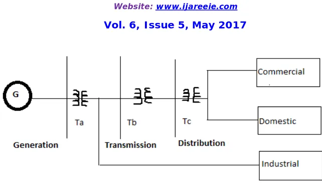
1.1 ELEMENTS OF ELECTRIC POWER SYSTEM
The power system today comprises of complex networks with hundreds of stations of generation and load centers are interconnected through power transmission lines:
1. Generation
2. Transmission
3. Distribution and
ISSN (Print) : 2320 – 3765 ISSN (Online): 2278 – 8875
I
nternational
J
ournal of
A
dvanced
R
esearch in
E
lectrical,
E
lectronics and
I
nstrumentation
E
ngineering
(An ISO 3297: 2007 Certified Organization)
Website: www.ijareeie.com
Vol. 6, Issue 5, May 2017
Fig 1.1 Basic elements of Electric power system
II. PROBLEM STATEMENT
With interconnected systems continually growing in size and extending over vast geographical regions, it is becoming increasingly more difficult to maintain synchronism between various parts of the system. The oscillations of low frequency power have become a major problem for small signal stability, which bounds the steady state power limits, which in turn affect the economy and security of the system. The installation of power system stabilizer can increase the system stability. Power system stabilizer can enhance damping, steady state stability margin, and mitigate low frequency oscillations.
III. POWER SYSTEM CONTROL
The advantage of electrical energy is that it can be easily transported and controlled with high efficiency. Following are the basic requirements to meet with for the better design of a power system:
1. There should be adequate “Spinning Reserves” for active and reactive power.
2. The system should provide power at minimum cost and minimum environmental impacts.
3. The “quality” of power supply must meet certain minimum standards with respect to following factors:
(a) Constant frequency
(b) Constant voltage and
(c) Reliability
3.1 POWER SYSTEM STABILITY
ISSN (Print) : 2320 – 3765 ISSN (Online): 2278 – 8875
I
nternational
J
ournal of
A
dvanced
R
esearch in
E
lectrical,
E
lectronics and
I
nstrumentation
E
ngineering
(An ISO 3297: 2007 Certified Organization)
Website: www.ijareeie.com
Vol. 6, Issue 5, May 2017
Fig 1.2 Classification of power system stability
Stability can also be defined as a condition of equilibrium between opposing forces; here the opposing forces are.
i) Electromagnetic torque (Te)
ii) Mechanical torque (Tm)
The speed remains constant and there is equilibrium between the two torques i.e. Tm and Te under steady state conditions. When the power system is subjected to small disturbance, the either torques can be resolved into two components,
ΔTe= TSΔδ+ TDΔω
IV. SINGLE MACHINE INFINITE BUS OPERATING CONDITIONS
A generator with terminal voltage of 1.0 pu is delivering power to a load having terminal voltage magnitude of 1.0 pu. The transmission line through which the load is fed has reactance Xe=0.4 pu.
The Table 4.1 to 4.5respectively give the generator data, operating points, derived initial conditions and computed Heffron-Philips constants respectively.
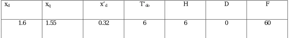
Table 4.1 Generator data
xd xq x’d T’do H D F
ISSN (Print) : 2320 – 3765 ISSN (Online): 2278 – 8875
I
nternational
J
ournal of
A
dvanced
R
esearch in
E
lectrical,
E
lectronics and
I
nstrumentation
E
ngineering
(An ISO 3297: 2007 Certified Organization)
Website: www.ijareeie.com
Vol. 6, Issue 5, May 2017
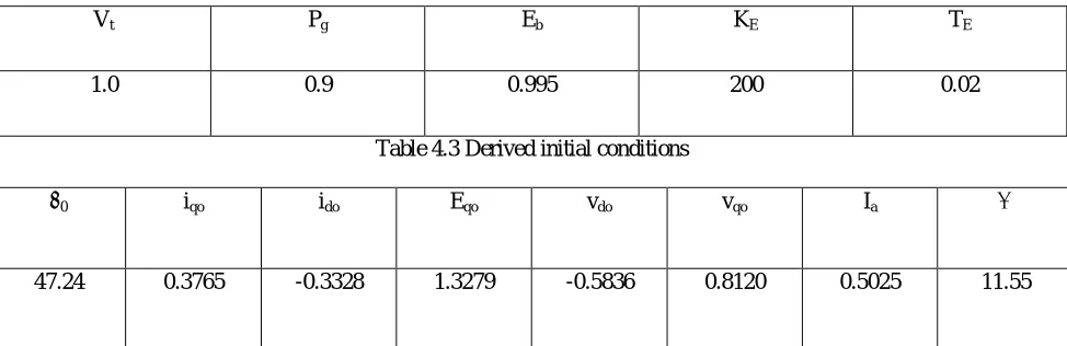
Table 4.2 Operating points
Vt Pg Eb KE TE
1.0 0.9 0.995 200 0.02
Table 4.3 Derived initial conditions
δ0 iqo ido Eqo vdo vqo Ia Θ
47.24 0.3765 -0.3328 1.3279 -0.5836 0.8120 0.5025 11.55
Table 4.4 Computed Heffron-Phillips constant
K1 K2 K3 K4 K5 K6
.9346 1.0198 .3600 1.3053 0.0500 0.4511
Table 4.4 Computed PSS parameters
TW Kstab T1 T2
1.4 20 0.154 0.033
The analysis is carried out using the above mentioned condition on:
I. SMIB system without PSS
ISSN (Print) : 2320 – 3765 ISSN (Online): 2278 – 8875
I
nternational
J
ournal of
A
dvanced
R
esearch in
E
lectrical,
E
lectronics and
I
nstrumentation
E
ngineering
(An ISO 3297: 2007 Certified Organization)
Website: www.ijareeie.com
Vol. 6, Issue 5, May 2017
4.1 SMIB SYSTEM WITHOUT PSS
Fig. 4.1 Simulation diagram for SMIB system without PSS.
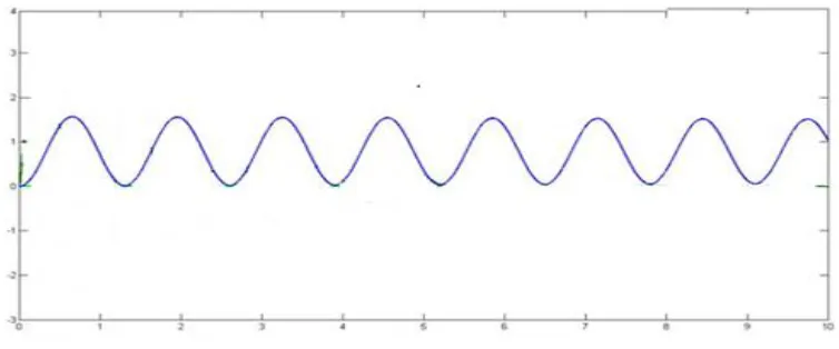
Fig. 4.2 & Fig. 4.3 represent the rotor angle deviation and speed deviation respectively
ISSN (Print) : 2320 – 3765 ISSN (Online): 2278 – 8875
I
nternational
J
ournal of
A
dvanced
R
esearch in
E
lectrical,
E
lectronics and
I
nstrumentation
E
ngineering
(An ISO 3297: 2007 Certified Organization)
Website: www.ijareeie.com
Vol. 6, Issue 5, May 2017
Fig. 4.3 Machine Rotor Angle Response of Original Model
From fig. 4.2 and fig. 4.3, the system is highly unstable as it doesn’t settle down to fixed operating point i.e. neither to fixed rotor angle nor to fix speed. The behavior of SMIB system without PSS is observed.
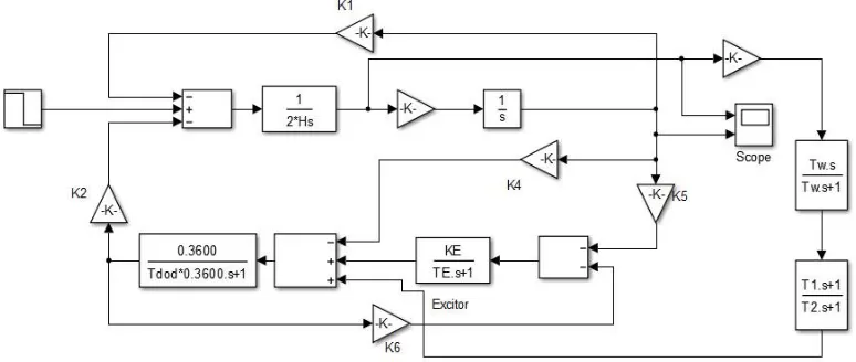
4.2 SMIB SYSTEM WITH PSS
In order to provide stability to the system, a power system stabilizer is added to the system which has generator speed as the input and whose output voltage is acting along with the exciter as additional input. The PSS parameters are determined in terms of phase characteristics.
Fig.4.4 Simulation model of SMIB system with PSS.
0 1 2 3 4 5 6 7 8 9 10
0 0.2 0.4 0.6 0.8 1 1.2 1.4 1.6
ISSN (Print) : 2320 – 3765 ISSN (Online): 2278 – 8875
I
nternational
J
ournal of
A
dvanced
R
esearch in
E
lectrical,
E
lectronics and
I
nstrumentation
E
ngineering
(An ISO 3297: 2007 Certified Organization)
Website: www.ijareeie.com
Vol. 6, Issue 5, May 2017
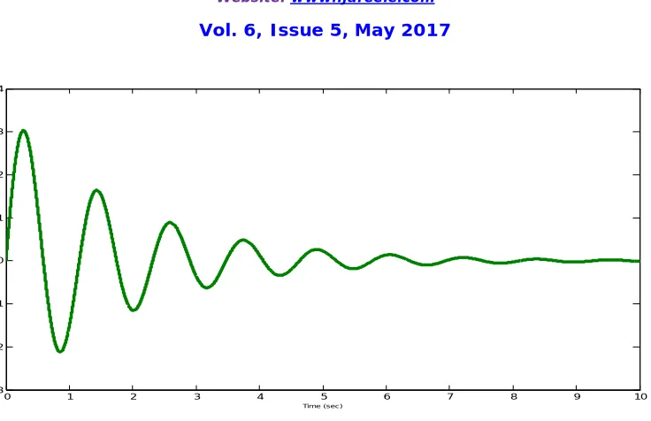
Fig.4.5 Machine Speed Deviation Response with PSS.
Fig. 4.6 Machine Rotor Angle Response with PSS
Fig. 4.5 and Fig. 4.6 shows the machine speed deviation and machine rotor angle response when PSS is connected to
previous SMIB system. It is observed that the oscillations are damping unlike in previous case, but the damping is not
desirable.
0 1 2 3 4 5 6 7 8 9 10
-3 -2 -1 0 1 2 3 4
Time (sec )
0 1 2 3 4 5 6 7 8 9 10
0 0.2 0.4 0.6 0.8 1 1.2 1.4
ISSN (Print) : 2320 – 3765 ISSN (Online): 2278 – 8875
I
nternational
J
ournal of
A
dvanced
R
esearch in
E
lectrical,
E
lectronics and
I
nstrumentation
E
ngineering
(An ISO 3297: 2007 Certified Organization)
Website: www.ijareeie.com
Vol. 6, Issue 5, May 2017
V. CONCLUSION
The low frequency oscillations damping was done with PSS controller. PSS system was tuned as per rotor angle and speed deviation characteristics of SMIB, under the operating conditions of the load, generation and loss of line. From the comparative simulation results of single machine infinite bus system with and without power system stabilizer, it is evident that the PSS based controller is more effective in damping power oscillations.
VI. FUTURE SCOPE
The present work can be extended to varying operating conditions and multi-machine system. Secondly The Fuzzy logic based PSS system was tuned as per rotor angle and speed deviation characteristics of the PSS controller under the varying operating conditions of the load. Also it can be further used to design an intelligent controller based on artificial neural net.
REFERENCES
[1] P. Kundur, Power System Stability and Control. New York: McGraw Hill, 1994.
[2] K.R. Padiyar, “Power System Dynamic Stability and Control”, second edition, BS publications, Hyderabad, 2002.
[3] Michael J. Basler, Richard C. Schaefer, “Understanding Power-System Stability”, IEEE transactions on industry applications, vol. 44, no. 2, march/april 2008.
[4] Doradla. PrathapHariKrishna,B. Venkatesh, “Design Of Power System Stabilizer to Improve Small Signal Stability By Using Modified Heffron-Phillip’s Model” International Journal of Engineering Science and Technology (IJEST), Vol. 3,ISSN : 0975-5462 June 2011. [5] Guillermo Castro, Juan Bermdez, Manuel Jimnez, Manuel Alvarez, Alex Arreaza “AVRs and PSSs revisited” 9th International Conference on
Electrical and Electronics Engineering (ELECO),IEEE publications November 2015.
[6] Seung-MookBae , “Sensitivity Analysis Based Optimization for Linear and Nonlinear Parameters in AVR to Improve Transient Stability in Power System” International Journal of Control and Automation Vol. 8, No. 7 year 2015.