Design of Novel Miniaturized Multilayer Substrate Integrated
Waveguide Filter and Tunable Filter
Mei Qian1, Wen-Xuan Xie2, and Kaiwei Zuo2, *
Abstract—A novel miniaturized multilayer substrate integrated waveguide (SIW) filter is designed. The filter is constructed with four compact SIW resonator cavities, and each cavity supports TE101
mode, which can be controlled by the slot located between layers. The area of the compact SIW resonator is just 1/16 of that of original substrate integrate waveguide (SIW) resonator. Meanwhile, the area of the four-order filter is 13.2 mm×26.4 mm. The insertion loss and return loss of the fabricated filter are −1.8 dB and −14.6 dB, respectively. Meanwhile, the tunable filter realizes center frequency linearity, which works at 1.6 GHz with an adjustable range of 51.8%. The insertion loss is −1.2 dB, and the return loss is less than −15 dB. The coplanar cavity coupling structure achieves a switchable bandwidth.
1. INTRODUCTION
Substrate integrated waveguide (SIW) is a popular technology which can provide an effective method to design low-cost, low-profile, and easy-integration microwave and millimeter wave circuits. However, SIW cavity has no advantage on plane size, and it is difficult to meet the needs of the next generation miniaturized communication systems. The technologies of half-mode SIW [1] and folded SIW [2] can realize miniaturized SIW cavity and keep the merits of conventional SIW cavity. On the other hand, the advent of multilayer technology is known to provide more freedom to design the miniaturized SIW circuits [3–5]. In [6], a compact full mode multilayer substrate integrated waveguide (SIW) filter using embedded mixed coupling is realized. Multilayer vertically stacked air-filled SIW [7] filtering topology can also realize small footprint. With multilayer LTCC technology, a dual-mode SIW cavity filter [8] has a compact and robust structure. In general, the size of these multilayer filters is still large. This is mainly because the coupling between compact multilayer SIW cavities is not easy to be implemented.
To realize the miniaturization of a multilayer substrate integrated waveguide filter, a novel compact SIW resonator is proposed and used to design a high performance multilayer filter in this paper. The compact resonator is obtained based on improving quarter mode SIW (IQMSIW) and is still operated in TE101 mode. A novel four-order multilayer filter is designed, and the center frequency of the filter is
2.92 GHz.
The insertion loss of the fabricated filter is −1.8 dB, and the return loss is below −14.6 dB. Meanwhile, a plane cascaded double-order tunable filter is designed and proved to achieve center frequency linearity, which works at 1.6 GHz with the adjustable range of 51.8%. The insertion loss is−1.2 dB, and the return loss is less than−15 dB.
Received 25 November 2018, Accepted 3 January 2019, Scheduled 11 January 2019
* Corresponding author: Kaiwei Zuo ([email protected]).
1 Guangdong Lingnan Institute of Technology, Guangzhou, Guangdong 510663, China. 2 Department of Information Engineering,
2. ANALYSIS OF THE COMPACT IMPROVED QMSIW RESONATOR
A compact resonator is the key to design a miniaturized filter. The proposed novel compact SIW resonator may be regarded as an improved QMSIW cavity. Fig. 1 illustrates the structure of the resonator, which is formed by stacking two quarter mode substrate integrated waveguide cavities. They are united through an L-shaped slot as a whole. Its height is two times of the conventional SIW, because it has two layers of substrate with height of h. The size of the L-shaped slot has great influence on the miniaturization of the resonator.
(a) (b)
Figure 1. (a) The structure of compact improved QMSIW resonator; (b) Middle metallic layer.
A compact resonator with 15×15 mm2area is designed on a Rogers RT/Duroid 5880 (tm) substrate with a relative dielectric constant of 2.2, thickness of 0.508 mm, and loss tangent of 0.0009. The L-shaped slot can reduce the TE101 mode resonance frequency of the compact resonator. In Fig. 2(a), as can be
seen, increasing the length of the L-shaped slot and reducing the width of it result in lower fundamental TE101 frequency. The position of the slot has a great influence on the resonant frequency of the cavity.
The simulation results from HFSS15.0 show that the resonant frequency would be decreased when the L-shaped slot is close to the metal vias wall. In fact, the L-shaped slot plays a role in energy coupling and produces capacitor effect. The capacitor value can be adjusted by the position and size of the L-shaped slot. The electric field distribution of the TE101 mode is different from that of a conventional
SIW. The maximum electric field is mainly located at the edge of the L-shaped slot in the intermediate layer metal, instead of the central region, as shown in Fig. 2(b). Simulation results show that the width of the compact IQMSIW cavity is nearly 1/4 of that of the original SIW in the same fundamental TE101
2 4 6 8 10 12 14 16 18 20 22
2.8 3.0 3.2 3.4 3.6 3.8 4.0 Fundam e n ta l T E101 f requency( G H z)
The length of L-shaped slot (mm)
(a) (b)
frequency as long as the L-shaped slot is long enough. Its width can be expressed by the following formula.
Weff = W SIW eff
4 + ΔW (1)
The resonant frequency of the mode of the compact improved QMSIW is given by following formula:
fm 0p= C 4√urεr
m
Weff
2
+
p Weff
2
(2)
wherem=p= 1,2,3. . .,ur andεr are the permeability and permittivity of the substrate, respectively.
Crepresents the speed of light in vacuum. Weff is the equivalent width of the compact resonator. WeffSIW
is the equivalent width of the original square SIW. ΔW is the addition width and observed owing to the unperfect magnetic wall of the two open edges of the proposed compact resonator.
3. MINIATURIZATION MULTILAYER FILTER DESIGN
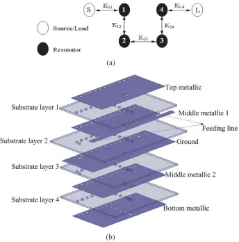
The proposed compact resonator is used to design a four-pole multilayer filter. The topology structure of the multilayer filter is shown as Fig. 3(a). The input (S) and output (L) are both coupled to adjacent resonators and denoted byKS1andKL4, respectively. There are two symmetrical non-coplanar
couplings denoted by K12 and K34 between resonators 1, 2 and resonators 3, 4, respectively. The
(a)
(b)
coplanar coupling between resonators 2 and 3 is denoted byK23. All of the coupling between resonators
is direct coupling, so a pure Chebyshev passband response in the four-order multilayer filter can be achieved.
The inter-resonator coupling coefficient and external quality factor are calculated using low-pass Chebyshev prototype valuesg0, . . . , g5 as
K12=
F BW
√g
1g2
, K23=
F BW
√g
2g3
, Qe= g0g1
F BW (3)
The filter is designed with the center frequency 2.9 GHz and bandwidth 399 MHz. A four-order Chebyshev filter with passband ripple of 0.01 dB is chosen as the prototype. According to [9], the coupling coefficient and external quality factor are as follows: K12 =K34 = 0.12811, K23 = 0.09847,
and Qe = QS1 = QL4 = 6.63. As shown in Fig. 3, the coupling between input (S) and resonator
1 is a direct coupling achieved through microstrip line, so as to output (L) and resonator 4. The magnetic coupling is achieved through the metal probe between resonator 1 and resonator 2 (resonator 3 and resonator 4). The probe is located at the edge of the L-shaped slot. The coupling value can be effectively modified and controlled by adjusting the position of the metal probe. Meanwhile, a U-shaped slot printed between resonator 2 and resonator 3 can excite mixed electric and magnetic couplings. The strength of mixed coupling is flexibly controlled by the U-shaped slot.
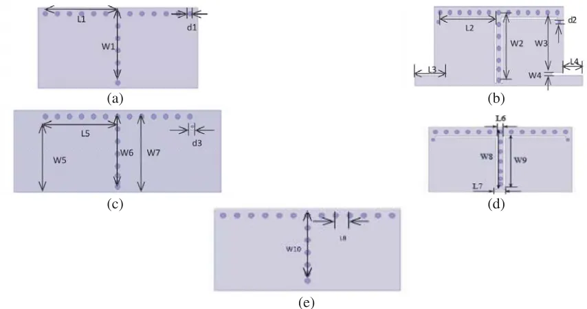
Figure 3 shows the structure of the multilayer filter which consists of five metallic layers and four substrate layers, and each substrate layer is between two metallic layers. The feed line using SIW-to-microstrip is located at Middle Metallic 1. Each top view of metallic layers is shown in Fig. 4, and the values of the parameters in the figure are given below: L1 = 12 mm, L2 = 11.5 mm, L3 = 6.35 mm,
L4 = 4 mm, L5 = 12.4 mm, L6 = 1 mm, L7 = 2 mm, L8 = 2 mm, W1 = 11.3 mm, W2 = 11.07 mm,
W3 = 8.85 mm, W4 = 0.5 mm, W5 = 10.6 mm, W6 = 11.3 mm, W7 = 12.2 mm, W8 = 11.8 mm,
W9 = 10.35 mm, W10 = 10.6 mm, d1 = 0.8 mm, d2 = 0.6 mm, d3 = 1 mm. Because the thickness of each substrate layer is only 0.508 mm, that of the filter which consists of four substrate layers is only 2.032 mm. The dimension of the whole filter is 13.2 mm×26.4 mm×2.032 mm.
The four-order multilayer filter is fabricated, and a picture of the filter is shown in Fig. 5. In microwave laboratory, the multilayer filter is measured. As shown in Fig. 5, the filter works at 2.92 GHz. The insertion loss and return loss are −1.8 dB and below −14.6 dB, respectively. The fractional
(a) (b)
(c) (d)
(e)
Figure 5. The simulated and measured results of the four-order multilayer filter.
Table 1. Comparisons with some related pseudo-elliptic filters presented in the references.
Ref. Technology f0 (GHz)/FBW IL (dB) Size (λ2g)
[3]I SIW/1-layer PCB 13.0/4.6% −1.7 0.35
[3]II SIW/2-layer PCB 13.2/4.5% −1.5 0.36
[4] SIW/2-layer LTCC 20/2.5% −1.9 0.46
[6] SIW/3-layer LTCC 9.97/2% −2.05 0.20
[7] AFSIW/5-layer PCB 33.03/10.1% −1 1.45
[8] SIW/7-layer LTCC 60/4.5% −4.9 0.22
[5] SIW/3-layer PCB 34.12/2.3% −5.46 0.25
This IQSIW/4-layer PCB 2.92/9.26% −1.8 0.03
λg is the guided wavelength of the center frequency.
bandwidth is about 13.7%. All measured data are obtained by Agilent N5230A Vector Network Analyzer and all simulated data obtained through Ansoft HFSS 15. Table 1 lists the performance comparison with some related multilayer SIW filters. It can be seen that the proposed filter provides smaller size and superior performance.
4. MINIATURIZED TUNABLE FILTER DESIGN
Since the compact improved QMSIW resonator cavity has two layers of dielectric and three layers of metal, and the feeding is in the middle metal layer, there are two kinds of schemes to disturb the cavity, as shown in Fig. 6.
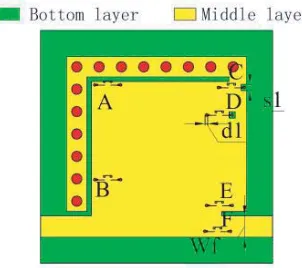
Figure 7 shows the disturbance of the energy distribution of the cavity when the tuning column is located at different positions in the cavity. The top view of the compact improved QMSIW tunable resonator is shown in Fig. 8. There are six switches in the tunable cavity: A, B, C, D, E, and F, which means that up to six tuning columns can be loaded. The dimensions of the cavity are referred in Table 2.
(a) (b)
Figure 6. Two schemes of tuning column structures.
Max
Min
f = 1.21 GHz0 f = 1.42 GHz0 f = 1.49 GHz0
f = 1.52 GHz0 f = 1.55 GHz0 f = 1.56 GHz0
Figure 7. Field distributions when tuning column is located at different positions.
Figure 8. Top view of compact improved QMSIW adjustable cavity.
Figure 9. Top view of compact improved QMSIW adjustable filter.
Table 2. Compact improved QMSIW cavity parameters (Unit: mm).
L1 Ls W1 K K1 K2 D b W f d1 s1 W f
18.2 16 15.6 0.5 2.9 0.5 1.2 2.6 2.5 0.3 0.7 2.5
Table 3. The coordinate position of tuning column and coupling column (Unit: mm).
Post x y Post x y
A 2.1 2.1 E 16.1 18.1
B 13.1 2.1 F 19.1 17.9
C 2.4 19.5 G 3.8 18.1
D 5.6 18.1 H 7.6 18.1
Figure 11. Frequency response with different number of tuning columns.
(a)
(a)
(b)
(c) (d)
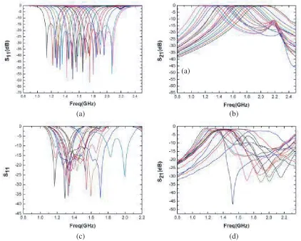
Figure 12. Simulation and measured results of the tunable filter. (a) Simulation results of S11; (b) Simulation results of S21; (c) Measured results of S11; (d) Measured results of S21.
Both layers of the main chamber are Rogers RT duroid 5880 (tm) (tanδ = 0.0009) with a thickness of 0.508 mm.
Figure 11 shows the simulated frequency response when different tuning columns are inserted. It can be found that when the number of short-circuited RF MEMS switches increases, the operating frequency of filter is shifted. However, the frequency response is in a decoupled state, and even some of the return loss does not meet the filter specifications.
Table 4 shows the 19 states corresponding to the combination of accessed tuning columns. ‘0’ represents open-circuited, and ‘1’ represents short-circuited. Figs. 12(a) and (b) show the simulated frequency response of the tunable filter. The insertion loss is greater than −1 dB and the return loss below−15 dB in all states, and the average frequency interval is 45 MHz.
Figure 13 shows the relationship between the adjustable state and frequency. It can be seen that center frequency of the planar structure of two-order compact improved QMSIW filter is linearly adjustable. Fig. 14 shows a photo of the planar structure of two-order compact improved QMSIW tunable filter. Figs. 12(c) and (d) show that center frequency of the filter is adjustable.
Figure 13. The relationship between the adjustable state and frequency.
Table 4. State corresponds to the tuning column combination.
State ABCDEF State ABCDEF State ABCDEF State ABCDEF
1 000000 6 010000 11 010010 16 110010
2 001000 7 101000 12 001111 17 011111
3 000100 8 100100 13 100011 18 111011
4 001100 9 001101 14 010011 19 110111
5 000001 10 011100 15 011011
5. CONCLUSION
A novel four-order multilayer filter is designed, and the filter shows a good performance. By using a vertical configuration in three-dimensional space and the compact improved QMSIW resonator, miniaturization of four-order filter is realized, and the area is just same as a two-order filter. At the center frequency of 2.92 GHz, the designed filter achieves a fractional bandwidth up to 9.26% and a high selectivity. The volume of the filter is 13.2 mm×26.4 mm×2.032 mm. The filter has compact size and simple structure, which make it competitive for application in microwave communication systems. The two-cavity filter with a planar structure using tuning column and planar adjustable coupling structure realizes a frequency which is 19-state linearly and continuously adjustable with an adjustable range of 1.2–2.03 GHz. The frequency response of all states meets the technical specifications.
REFERENCES
1. Wu, L.-S., X.-L. Zhou, W.-Y. Yin, C.-T. Liu, L. Zhou, J.-F. Mao, and H.-L. Peng, “A new type of periodically loaded half-mode substrate integrated waveguide and its applications,” IEEE Trans. Microwave Theory Tech., Vol. 58, No. 4, 882–893, 2010.
2. Kai, K. Z., et al., “A novel miniaturization double folded quarter mode substrate integrate waveguide tunable filter design in LTCC,”IEEE Conference ICMMT, 1–4, 2018.
3. Jia, D., Q. Feng, Q. Xiang, et al., “Multilayer Substrate Integrated Waveguide (SIW) filters with higher-order mode suppression,”IEEE Microwave & Wireless Components Letters, Vol. 26, No. 9, 678–680, 2016.
4. Wei, Q. F., Z. F. Li, L. S. Wu, et al., “A novel multilayered cross-coupled Substrate-Integrated Waveguide (SIW) circular cavity filter in LTCC,”Microwave&Optical Technology Letters, Vol. 51, No. 7, 1686–1689, 2010.
5. Shen, M., Z. Shao, X. Du, et al., “Ka-band multilayered substrate integrated waveguide narrowband filter for system-in-package applications,” Microwave& Optical Technology Letters, Vol. 58, No. 6, 1395–1398, 2016.
6. Xu, Z. Q., P. Wang, K. W. Qian, et al., “Substrate Integrated Waveguide filter with embedded mixed source-load coupling,”Electronics Letters, Vol. 49, No. 23, 1464–1465, 2013.
7. Parment, F., A. Ghiotto, T. P. Vuong, et al., “Ka-band compact and high-performance bandpass filter based on multilayer air-filled SIW,”Electronics Letters, Vol. 53, No. 7, 486–488, 2017. 8. Wang, D., K. S. Chin, W. Che, et al., “Compact 60 GHz low-temperature cofired ceramic filter
with quasi-elliptic bandpass response,” IET Microwaves Antennas& Propagation, Vol. 10, No. 6, 664–669, 2016.