A Novel Three-Parameter Fully Tunable BP Filter
Kaiwei Zuo, Yong Zhong Zhu*, Le Li, Zheyu Li, Guohao Peng, and Xiaoyu Liu
Abstract—The research and development of microwave-tunable equipment has promoted the advancement of electronic countermeasures and electronic surveillance in the field of military communications. The research of fully tunable filters is a hotspot in the field of tunable filter research. Parameters such as center frequency (CF), absolute bandwidth (ABW), and transmission zero (TZ) are important indicators of fully tunable filters. In this paper, a high-performance fully tunable substrate integrated waveguide filter is designed and fabricated to achieve constant ABW (100 MHz) and TZ (1.59 GHz) with CF tunable, and the adjustable range is 1.1–1.3 GHz. Meanwhile, the constant CF (1.15 GHz) is achieved with the ABW tunable, and the adjustable range is 70–120 MHz. Also the constant ABW (100 MHz) and CF (1.14 GHz) are achieved with the TZ tunable, and the adjustable range is 1.59–1.89 GHz. The measured results show that the insertion loss of the tunable filter is lower than 2.04 dB, and the return loss is greater than 20 dB.
1. INTRODUCTION
Tunable filter is a key component that satisfies the intelligent requirements of adaptive regulation of the RF front end. The study of fully tunable filters is of great significance for current spectrum resources and intense electronic countermeasures. Tunable parameters of a current tunable filter mainly include center frequency [1, 2], bandwidth [3, 4], transmission zero [5, 6] and order [7], The research of high-performance tunable filter is beneficial for selecting the required signal frequency from complex and variable spectrum environment, flexibly suppressing various interferences, realizing adaptive regulation of the system, achieving miniaturization and integration effects, and reducing filter cost.
While a single indicator of a filter is tunable, many scholars have studied the high performance of a fully tunable filter. In [8], varactor diodes were used to realize microstrip filters with tunable CF, ABW, and TZ. However, the measured results of such filters showed high insertion loss. ABW and TZ changed simultaneously while achieving tunable CF. Ref. [9] made a fully tunable filter using substrate integrated waveguide, which improved the overall transmission performance of the filter, but also failed to make other indicators constant when the single index was tunable.
Based on the previous research on miniaturized substrate integrated waveguide microwave filters, this paper analyzes the equivalent circuit and resonance characteristics of a resonant cavity by using a miniaturized substrate integrated waveguide resonator [10]. On this basis, a high-performance fully tunable microwave filter with tunable CF, ABW, and TZ is designed and fabricated by using the method of odd-even mode analysis. The controllable and tunable implementation of multiple parameters of the microwave filter is an innovation of this research. The fully tunable filter is fabricated to achieve constant ABW (100 MHz) and TZ (1.59 GHz) with CF tunable, and the tunable range is 1.1–1.3 GHz. Meanwhile, the constant CF (1.15 GHz) is achieved with the ABW tunable, and the adjustable range is 70–120 MHz. Also constant ABW (100 MHz) and CF (1.14 GHz) are achieved with the TZ tunable, and the adjustable range is 1.59–1.89 GHz. The measured results show that the insertion loss of the tunable filter is lower than 2.04 dB, and the return loss is greater than 20 dB.
Received 11 July 2019, Accepted 13 August 2019, Scheduled 3 September 2019
* Corresponding author: Yong-Zhong Zhu ([email protected]).
2. FULLY TUNABLE FILTER DESIGN
Figure 1. Evolution process of the miniaturized resonator.
The miniaturized SIW resonator is a combination of a double folding technique and a quarter mode integrated waveguide technology as shown in Fig. 1. Consider a square-shaped SIW resonator with a widthL, which transmits the resonant frequency of the TEmop mode as Eq. (1).
fmop = C
2√εrμr
mπ Leff
2
+
pπ Leff
2
(1)
Leff = L−1.08d
2
P + 0.1 d2
L (2)
where C is the speed of light in the vacuum; d is the diameter of the metallized via hole of the cavity; P is the spacing of the metallized via hole, which satisfies P < λ/4 and P < 4d; λ is the resonant wavelength; εr and μr respectively represent the relative magnetic permeability and relative
conductivity of the dielectric plate;Leff is the equivalent width when the SIW cavity is converted into a rectangular waveguide. In the structure, TE102 and TE202 modes in the original cavity disappear, and only the dominant mode TE101 is considered. Therefore, the resonant frequency of the cavity is [11]:
fMSIW = C
4√2μrεrLMSIW (3)
LMSIW = Leff/4 + ΔL (4)
where LMSIW is the equivalent width of the miniaturized SIW resonator, and ΔL is the additional
width. ΔL is observed owing to the varied feeding position, and the magnetic walls are not ideal due to fringing fields.
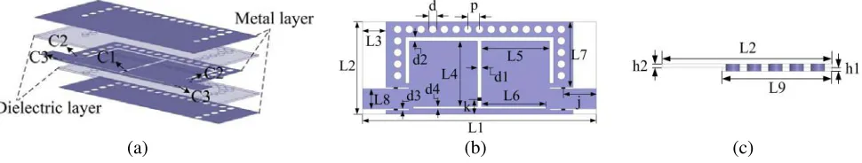
The overall structure of the two-cavity fully tunable filter is shown in Fig. 2(a). On the basis of the capacitive coupling of the upper and lower layers of the original cavity, the cavity also adopts the gap coupling. In order to improve the out-of-band selectivity of the filter, a slot whose width equal tod4 is introduced between the source and the load. In order to adjust the CF, ABW, and TZ of the filter, five varactor diodes are introduced inC1, C2, and C3. The positions of the varactor diodes are marked in Fig. 2(b). The overall size parameters of the filter are listed in Table 1.
(b)
(a) (c)
Table 1. Two-cavity fully tunable filter structure (Unit: mm).
L1 L2 L3 L4 L5 L6 L7 L8 L9 d
60 24 6 17 17.5 16.5 17 5.2 15.5 2
P j k h1 h2 d1 d2 d3 d4
3 8.5 3.9 0.508 0.508 1 1 0.4 0.5
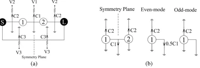
In order to simplify the filter analysis process, the filter equivalent circuit is simplified into the form of the cavity topology and the tunable structure in Fig. 3. In Fig. 3(a), two resonators are connected in series with the source and load to form the filter structure. In the topological form of the filter, varactor C1 is loaded between the two resonant cavities to change the inter-cavity coupling, C2 loaded between the resonant cavity and the source or the load to change the resonant frequency, C3 loaded between the source and the load, and the source and load coupling is changed which changes the transmission zero of the filter.
Taking the intermediate symmetry plane as a reference, the cavity is analyzed by means of odd-even mode analysis [11], and the simulation results shown in Fig. 4 are obtained by combining theoretical analysis with Ansoft simulation.
(b) (a)
Figure 3. Equivalent circuit analysis. (a) Adjustable structure equivalent circuit. (b) Even-mode and odd-mode analysis.
Table 2. Comparison of research results.
Ref. Tunable parameter
Constant parameter
CF (GHz)
ABW (MHz)
TR (GHz)
IL
(dB) Size
[10] CF ABW 1.5–2.2 170 / 3.2–5.1 40 mm×30 mm CF&ABW&TR / 1.5–2.2 40–170 1.64–1.37 3.1–6.5
[11] CF&ABW / 0.8–1.5 216–534 / / 35 mm×12 mm
[12] ABW CF
1.72 225-310
/ 1.18-6.32 71.8 mm×30 mm 1.45 97–213
1.21 62–101
[13] CF&ABW&TR / 1.25–2.1 54–162
Lower to upper stopband
39 mm×18 mm
This work
CF ABW&TR 1.1–1.3 100 1.59 1.85
60 mm×24 mm ABW CF 1.15 70–120 / 2.04
TR CF&ABW 1.14 100 1.59–1.89 1.96
(b) (a)
(c)
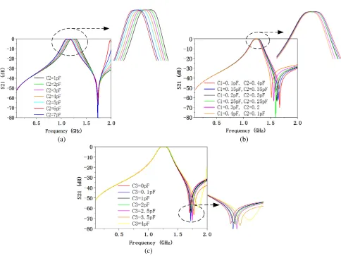
Figure 4. Analysis of tunable characteristics. (a) Tunable center frequency. (b) Tunable bandwidth. (c) Tunable transmission zero.
In Fig. 4(a), whenC1 andC3 are not connected to the filter, the capacitance ofC2 is changed to 1– 7 pF by changing the voltage across the varatorC2. The CF of the tunable filter is kept adjustable from 1.1 GHz to 1.32 GHz. The ABW remains unchanged at approximately 180 MHz, and the passband TZ is fixed at 1.75 GHz. In Fig. 4(b), since the bandwidth is mainly determined by the coupling coefficient between the two cavities, the odd-even mode method analysis method shows that the coupling coefficient is proportional to C1 and inversely proportional to C2. In order to keep the CF constant with ABW tunable, C3 does not access the filter. By changing the capacitance value ofC1 from 0.1 to 0.4 pF, the capacitance value ofC2 changes from 0.4 to 0.1 pF; the CF is kept constant at 1.24 GHz; and the ABW is changed within 175-65 MHz. In Fig. 4(c), C1 andC2 do not access the filter. When the capacitance of diode C3 changes from 0 to 4 pF, the CF of the filter remains unchanged at 1.23 GHz; the ABW remains constant at 160 MHz; and the TZ is tunable in the range of 1.7–1.85 GHz.
3. FABRICATION AND MEASUREMENT
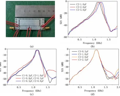
Coplanar waveguides and microstrip lines are used for feeding, as shown in Fig. 5(a). Using the feed structure of the upper or intermediate metal layer, the filter is matched to the source and load to achieve filter characteristics.
(b) (a)
(d) (c)
Figure 5. Physical map and measured results of fully tunable filter. (a) Physical map of filter. (b) Tunable center frequency. (c) Tunable bandwidth. (d) Tunable transmission zero.
upper and lower layers of the original cavity, the cavity also adopts the gap coupling. In order to improve the out-of-band selectivity of the filter, a slot is introduced between the source and the Load. By applying DC voltage to three varactor diodes at five different positions on the filter, the capacitance value of the varactor is changed, and the multiple indicators of the filter are fully tunable. Varactor diode adopts SMV2020-079 model, and SMA connector is connected with source and load.
Compared with the previous research results in Table 2, the fully tunable filter not only realizes the full adjustment of the CF, ABW and TZ, but also keeps the remaining indicators constant while the single index is tunable.
4. CONCLUSION
In this paper, a miniaturized SIW resonant structure is proposed, and the resonant characteristics of the resonant cavity are analyzed. A two-cavity fully tunable SIW filter is designed and fabricated by loading the varactor diode. The filter realizes the tunable CF with the ABW and TZ constant. Meanwhile, the ABW is tunable when the CF is constant, and the TZ is tunable when the CF and ABW are constant. Compared with the previous research results, the tunable performance is better improved.
ACKNOWLEDGMENT
REFERENCES
1. Esmaeili, M. and J. Bornemann, “Novel tunable bandstop resonators in SIW technology and their application to a dual-bandstop filter with one tunable stopband,” IEEE Microwave and Wireless Components Letters, Vol. 27, No. 1, 40–42, 2017.
2. Zuo, K., Y. Zhu, et al., “A novel miniaturized quarter mode substrate integrate waveguide tunable filter,” IEICE Electronics Express, Vol. 15, No. 7, 1–6, 2018.
3. Lan, B., C. Guo, and J. Ding, “A fully tunable two-pole bandpass filter with wide tuning range based on half mode substrate integrated waveguide,” Microwave & Optical Technology Letters, Vol. 60, 2018.
4. Naeem, U., M. B. Khan, and M. F. Shafique, “Design of compact dual-mode dual-band SIW filter with independent tuning capability,” Microwave and Optical Technology Letters, Vol. 60, No. 1, 178–182, 2018.
5. Amari, S., U. Rosenberg, and J. Bornemann, “Adaptive synthesis and design of resonator filters with source/load-multiresonator coupling,” IEEE Transactions on Microwave Theory and Techniques, Vol. 50, No. 8, 1969-1978, 2002.
6. Lu, D., T. F. Yan, and X. H. Tang, “Compact quasi-elliptic combline filter in single-layered SIW technology with two tunable transmission zeros,” Wireless & Microwave Technology Conference, IEEE, 2016.
7. Sigmarsson, H. H., J. Lee, D. Peroulis, et al., “Reconfigurable-order bandpass filter for frequency agile systems,” Microwave Symposium Digest, IEEE, 2010.
8. “Compact frequency and bandwidth tunable bandpass-bandstop microstrip filter,” IEEE Microwave and Wireless Components Letters, 1–3, 2018.
9. You, B., L. Chen, and G. Luo, “The novel reconfigurable double-layer half-mode SIW filter with tunable DMS structure,”Journal of Electromagnetic Waves and Applications, 1–8, 2018.
10. Zhu, Y. Z., “A compact double folded quarter mode substrate integrated waveguide (DFQMSIW) filter,” IEICE Electronics Express, Vol. 13, No. 11, 20160330–20160330, 2016.