Pandian Saraswathi Yadav Engineering College, Arasanoor, Sivagangai, Tamilnadu, India
PFC Based DC Variable Voltage Converter
Fed BLDC Motor Drive
R.S.Jothilakshmi
1, Dr.I.Gerald Christopher Raj
2, Dr. S.K.Nandhakumar
3Department of EEE, PSNA College of Engineering and Technology, Dindigul, Tamilnadu, India1,2,3
ABSTRACT: This paper presents a power factor corrected (PFC) variable DC converter fed brushless dc motor (BLDCM) drive as a cost effective solution for low-power household applications. The variable DC converter operation is based on canonical switching cell (CSC) topology. The speed of BLDCM is controlled by varying the dc-bus voltage of voltage source inverter (VSI). The BLDCM is electronically commutated for reduced switching losses in VSI due to low-frequency switching. A front-end CSC converter operating in discontinuous inductor current mode (DICM) is used for dc-bus voltage control with unity power factor at ac mains. A single sensor for dc-bus voltage sensing is used for the development of the proposed drive, which makes it a cost-effective solution. The performance of the proposed drive is evaluated over a wide range of speed control and variable loading conditions with improved power quality at ac mains. The performance of the proposed drive is simulated in MATLAB/Simulink environment.
KEYWORDS: Brushless dc motor, canonical switching cell converter, discontinuous inductor current mode, power factor correction, power quality.
I.INTRODUCTION
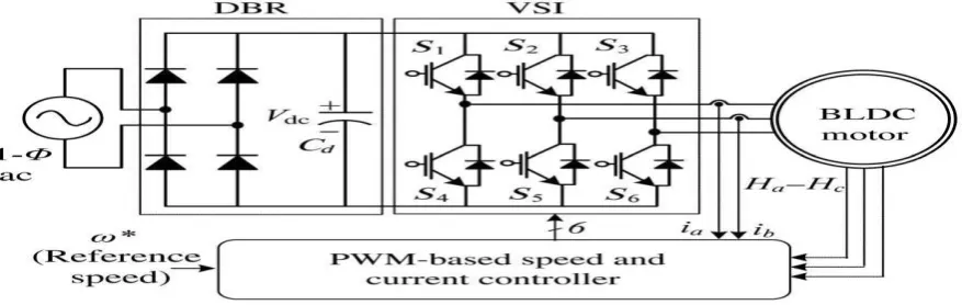
mong numerous motors, brushless dc motor (BLDCM) is favorite in many low and medium power applications including household appliances, industrial tools, heating ventilation and air conditioning (HVAC), medical equipment, and precise motion control systems [1]–[7]. BLDCM is preferred because of its high torque/inertia ratio, high efficiency, ruggedness, and low-electro-magnetic interference (EMI) problems [1], [2]. The stator of the BLDCM comprises of three-phase concentrated windings and rotor has permanent magnets [1], [2]. It is also recognized as an electronically commutated motor (ECM) since an electronic commutation created on rotor position via a three-phase voltage source inverter (VSI) is used [8], [9]. Thus, the problems associated with brushes, such as sparking, and wear and tear of the commutator assembly are excluded.Fig. 1 shows a conventional arrangement of BLDCM drive fed by an uncontrolled rectifier and a dc-link capacitor followed by athree-phase VSI, which is based on pulse width modulation (PWM) is used for feeding the BLDCM [10]. This type of arrangement draws
peaky, harmonic rich current from the supply
Pandian Saraswathi Yadav Engineering College, Arasanoor, Sivagangai, Tamilnadu, India
and leads to a high value of total harmonic distortion (THD) of supply current and very low power factor at its supply mains. A very high THD of supply current of 65.3% and a very poor power factor of 0.72 is realized.
A front-end power factor correction (PFC) converter is used after the diode bridge rectifier (DBR) for refining the quality of power and attaining a near unity power factor at ac supply mains. The continuous inductor current mode (CICM) and the dis-continuous inductor current mode (DICM) are the two basic modes of operation of a PFC converter. A control of current multiplier is normally used for PFC converter operating in CICM and requires three sensors (2-V, 1-C) for the operation which is not cost-effective for low-power applications, whereas, a PFC converter operating in DICM uses a voltage follower control which requires sensing of dc-link voltage for voltage control and natural PFC is attained at ac mains [13], [14].
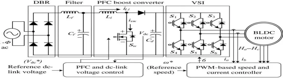
Many topologies of a PFC-based BLDCM drives have been stated in the literature [10], [15]–[23]. A boost PFC converter has been the most popular arrangement for feeding BLDCM drive as shown in Fig. 2 [16]–[18]. A constant dc-link voltage is conserved at the dc-link capacitor and a PWM-based VSI is used for the speed control. Hence, the switching losses in VSI are very high due to high switching PWM signals and require huge quantity of sensing for its operation. Cheng [19] has proposed an active rectifier-based BLDC motor drive fed which requires complex control and is suitable for higher power applications.
Fig.2. Conventional BLDCM drive with PFC converter
Lee et al. [20] have discoverednumerous reduced parts formations for PFC operation which also uses a PWM-based VSI and have high switching losses in it. A buck chopper operating as a front-end converter for feeding a BLDC motor drive has been projected by Barkley et al. [21]. It also has greater switching losses associated with it due to high-frequency switching. Madani et al. [22] have suggested a boost half bridge PFC-based BLDCM drive using four switch VSI. This also needsanessential PWM operation of VSI and PFC half bridge boost converter, which presents high switching losses in the whole system.
These switching losses are condensed by using anidea of variable dc-link voltage for speed control of BLDC motor [24]. This exploits the VSI to operate in low-frequency switching mandatory for electronic commutation of BLDC motor, thereforecondenses the switching losses related with it. The front-end SEPIC and Cuk converter serving a BLDC motor using a variable voltage control have been offered in [10] and [23], but at the cost of two current sensors. This paper presents the development of a reduced sensor-based BLDC motor drive for low-power application.
II.PROPOSEDDRIVEUSINGIMPROVED DCCONVERTER
Pandian Saraswathi Yadav Engineering College, Arasanoor, Sivagangai, Tamilnadu, India
Fig.3. Proposed BLDCM drive fed from CSC converter
Anadjustable dc-bus voltage of the VSI is used for controlling the speed of the BLDCM. This operates the VSI in low-frequency switching by electronically commutating the BLDCM for reducing the switching losses in six insulated gate bipolar transistor’s (IGBT’s) ofVSI which share the major portion of total losses in the BLDCM drive. The front-end CSC converter is designed and its parameters are selected to operate in a DICM for obtaining a high-power factor at wide range of speed control.
III. OPERATING PRINCIPLE OF PROPOSED DC CONVERTER
The proposed BLDCM drive uses a CSC converter working in DICM [25]–[28]. In DICM, the current in inductor
𝐿𝑖 becomes discontinuous in a switching period ( 𝑇𝑠). Three states of CSC converter are shown in Fig. 4(a)–(c). Three modes of operation are described as follows.
Mode I: As shown in Fig. 4(a), when switch𝑆𝑤 is turned ON, the energy from the supply and stored energy in the intermediate capacitor𝐶1 are moved to inductor 𝐿𝑖. In this process, the voltage across the intermediate capacitor𝑉𝐶1 reduces, while inductor current 𝑖𝐿𝑖and dc-link voltage𝑉𝑑𝑐 are augmented. The designed value of intermediate capacitor is large enough to hold enough energy such that the voltage across it does not become discontinuous.
Fig.4 (a).Operation of CSC converter in Mode I
Pandian Saraswathi Yadav Engineering College, Arasanoor, Sivagangai, Tamilnadu, India
Fig.4 (b).Operation of CSC converter in Mode II
Mode III: This is the discontinuous conduction mode of operation as inductor𝐿𝑖 is entirely discharged and current
𝑖𝐿𝑖becomes zero as shown in Fig. 4(c). The voltage across intermediate capacitor 𝐶1 remains to increase, while dc-link capacitor supplies the essential energy to the load, hence 𝑉𝑑𝑐starts falling.
Fig.4 (c).Operation of CSC converter in Mode III
IV.DESIGN OF IMPROVED VARIABLE DC CONVERTER
The proposed BLDCM drive uses a PFC-based CSC converter operating in DICM. The voltage appearing after the DBR is given as
𝑉𝑖𝑛= 2 2𝑉𝑆
𝜋 ……….(1)
A nominal duty ratio (𝑑𝑛) corresponding to𝑉𝑑𝑐𝑛 is as
𝑑𝑛= 𝑉𝑉𝑑𝑐𝑛
𝑑𝑐𝑛+𝑉𝑖𝑛……….(2)
Pandian Saraswathi Yadav Engineering College, Arasanoor, Sivagangai, Tamilnadu, India
cell which isa combination of a switch𝑆𝑤, diode 𝐷, and an intermediatecapacitor 𝐶1[14]. The critical value of inductance 𝐿𝑖𝑐 to operateat boundary condition is given as
𝐿𝑖𝑐=𝑉2𝐼𝑖𝑛𝑑𝑛𝑜𝑚
𝑖𝑛𝑓𝑆 …………..(3)
Where𝐼𝑖𝑛 is inductor, (𝐿𝑖) current, and 𝑓𝑠 is switching frequency. Now to operate this converter for PFC even at very low duty ratio, the value of inductor is taken around 1/10 th of the critical value [29]. Hence, it is
𝐿𝑖= 𝐿𝑖𝑐
10………(4)
An intermediate capacitor 𝐶1 is designed for permitted ripple voltage of ∆𝑉𝐶1across it and it is taken as 10% of 𝑉𝐶, where 𝑉𝐶 is the voltage across intermediate capacitor
𝐶1=𝑉𝑑𝑐𝑛𝑜𝑚𝑓 𝑑𝑛𝑜𝑚
𝑆𝑅𝐿∆𝑉𝐶1 …………(5)
Where 𝑅𝐿 is the equivalent emulated load resistance. Now for a permitted ripple of 1% of the nominal dc-link voltage across the dc-link capacitor (𝐶𝑑), the value of dc-link capacitor is calculated as
𝐶𝑑=2𝜔𝐼𝑑
𝐿∆𝑉𝑑𝑐………(6)
where𝜔𝐿 is line frequency in rad/s and 𝐼𝑑 is dc-link current.
To avoid the reflection of high-order harmonics in supply system, a low-pass inductive-capacitive (LC) filter is designed
whose maximum value, 𝐶𝑚𝑎𝑥 is calculated as
𝐶𝑚𝑎𝑥 = 𝐼𝑝𝑒𝑎𝑘
𝜔𝐿𝑉𝑝𝑒𝑎𝑘 tan(𝜃)……(7)
Where𝐼𝑝𝑒𝑎𝑘 and 𝑉𝑝𝑒𝑎𝑘 are amplitudes of supply current and supply voltage and 𝜃 is the displacement angle between them. Now, the value of filter inductor is designed by considering thesource impedance (𝐿𝑠) of 4%–5% of the base impedance. Hence, the additional value of inductance required is given as
𝐿𝑓 = 𝐿𝑟𝑒𝑞 + 𝐿𝑠 → 1 4𝜋2𝑓
𝑐2𝐶𝑓….(8)
V.SIMULATION MODEL OF IMPROVED VARIABLE DCCONVERTER FED BLDCM DRIVE
Pandian Saraswathi Yadav Engineering College, Arasanoor, Sivagangai, Tamilnadu, India
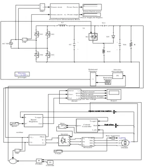
Fig. 5.Simulink Modelof proposed BLDCM drive fed from improved variable DC converter
VI.SIMULATED PERFORMANCE OF PROPOSED BLDCM DRIVE
The performance of the proposed BLDCM drive is simulated in MATLAB/Simulink environment using the Sim-
Fig. 6.Dynamic performance of proposed BLDCM drive during speed and torque command variations
_ + Li Lf _ + rectifier Discrete, Ts = 2e-005 s.
p owergui iLi1 mot or Conv. Ct rl i_a speed T em v_dc demux Vdc Vc1 v + -VM 1 v+ -VM Torque g D S Sw N N* T orque* Ct rl Sp eed Regulator Sp eed Scop e1 Rep eating Sequence <= Relational Op erator RT Rate Transition R Product V(max) sinwt
I(max) sin(wt - x) P ower Fact or
P ower Angle
Power Factor M easurement Block
Power Factor (cosx)
Power Angle (In Degree)
m A B C Tm PM SM gat es m g M ux I_abc T a T b T c Mt a Mt b Mt c M easures PI Discrete PI Controller D5 D4 D3 D2 D1 20 Constant Cf i + -CM Meas. V L+ V L-V + V -AC VS g A B C + Inverter T orque* Hall I_abc gat esControllerCurrent
Stator current Rotor sp eed Electromagnetic Torque DC bus voltage
Hall effect Hall effect Hall effect Hall effect Hall effect Hall effect Hall effect Hall effect Hall effect Hall effect Hall effect Hall effect <Rotor sp eed wm (rad/s)> <Rotor sp eed wm (rad/s)> <Rotor sp eed wm (rad/s)> <Rotor sp eed wm (rad/s)> <Rotor sp eed wm (rad/s)> <Rotor sp eed wm (rad/s)> <Rotor sp eed wm (rad/s)> <Rotor sp eed wm (rad/s)> <Rotor sp eed wm (rad/s)> <Rotor sp eed wm (rad/s)> <Rotor sp eed wm (rad/s)> <Rotor sp eed wm (rad/s)>
-20 0 20 St ator C ur rre nt (Ia ) i n A -500 0 500 Spe ed (N ) i n RP M -20 0 20 Tor que (T e) in Nm
0 0.1 0.2 0.3 0.4 0.5 0.6 0.7 0.8 0.9 1
-1000 0 1000
Time in Seconds
Conv er ter V ol tage (V dc ) i n V
Motor Speed Estimated speed
Pandian Saraswathi Yadav Engineering College, Arasanoor, Sivagangai, Tamilnadu, India
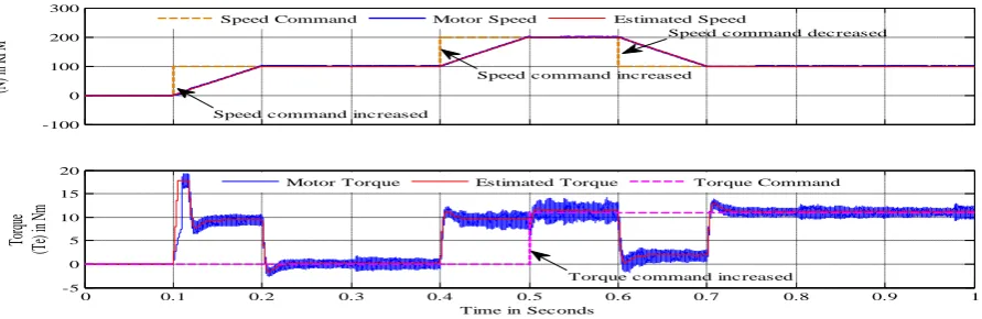
Fig. 7.Dynamic performance of proposed BLDCM drive during speed and torque command variations along with estimated speed and torque
Fig.8.Variation of PF during speed and torque command variations
Fig.9.Variation of PF during speed command variation at 0.5 seconds -100
0 100 200 300
Spe
ed
(N
) i
n R
PM
0 0.1 0.2 0.3 0.4 0.5 0.6 0.7 0.8 0.9 1
-5 0 5 10 15 20
Time in Sec onds
Tor
que
(T
e)
in
Nm
Speed Command Motor Speed Estimated Speed
Motor Torque Estimated Torque Torque Command
Speed c ommand inc reased
Speed c ommand inc reased
Torque c ommand inc reased
Speed c ommand dec reased
0 0.1 0.2 0.3 0.4 0.5 0.6 0.7 0.8 0.9 1
0 0.1 0.2 0.3 0.4 0.5 0.6 0.7 0.8 0.9 1
Time in Sec onds
Pow
er
Fa
ctor
0 0.05 0.1 0.15 0.2 0.25 0.3 0.35 0.4 0.45 0.5
0.8 0.82 0.84 0.86 0.88 0.9 0.92 0.94 0.96 0.98 1
Time in Sec onds
Pow
er
Fa
ctor
Pandian Saraswathi Yadav Engineering College, Arasanoor, Sivagangai, Tamilnadu, India
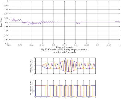
Fig.10.Variation of PF during torque command variation at 0.5 seconds
Fig.11.Induced EMFs and Hall Position Sensing under transient conditions of proposed BLDCM drive
Fig. 12.Induced EMFs and Hall Position Sensing under transient conditions of proposed BLDCM drive
0.5 0.55 0.6 0.65 0.7 0.75 0.8 0.85 0.9 0.95 1
0.8 0.82 0.84 0.86 0.88 0.9 0.92 0.94 0.96 0.98 1
Time in Seconds
Pow er F ac tor -20 -10 0 10 20 Indu c e d E M F s a , b, c A m pl it ude i n V ol ts
0 0.1 0.2 0.3 0.4 0.5 0.6 0.7 0.8 0.9 1
0 0.5 1 1.5
Time in Seconds
H a ll S e ns or H a , H b, H c A m pl it ude i n vol ts -20 -10 0 10 20 Indu ce d E M F s a, b, c A m pl it ude i n V ol ts
0 0.05 0.1 0.15 0.2 0.25 0.3 0.35 0.4 0.45 0.5 0
0.5 1 1.5
Time in Seconds
Pandian Saraswathi Yadav Engineering College, Arasanoor, Sivagangai, Tamilnadu, India
Fig. 13. Induced EMFs and Hall Position Sensing under transient conditions of proposed BLDCM drive
Power-System toolbox. The simulation parameters are listed in table I. The performance evaluation of the proposed drive is categorized in terms of the performance of the BLDC motor and improved variable DC converter and the achieved power quality indices obtained at ac mains. The parameters associated with the BLDC motor such as speed (𝑁), electromagnetic torque (𝑇𝑒), and stator current (𝑖𝑎) are analyzed for the proper functioning of the BLDC motor. Parameters such as supply voltage (𝑉𝑠), supply current (𝑖𝑠), dc link voltage (𝑉𝑑𝑐), of improved DC converter are evaluated to demonstrate its proper functioning. Moreover, power quality indices such as power factor (PF) total harmonic distortion (THD) are analyzed for determining power quality at ac mains.
VII. CONCLUSION
PFC Based DC Variable Voltage Converter fed BLDC drive has been proposed for targeting low-power domestic applications. Anadjustable voltage of dc bus has been used for controlling the speed of BLDCM which ultimately has given the freedom to operate VSI in low-frequency switching mode for reduced switching losses. A front-end CSC converter operating in DICM has been used for dual objectives of dc-link voltage control and realizing almost unity power factor at ac mains. The performance of the proposed drive has been found quite well for its operation at variation of speed over a wide range and also variable loading conditions. A prototype of the CSC-based BLDCM drive has to beimplementing with satisfactory test results for its operation over complete speed range and its operation at universal ac mains in future.
TABLEI
SIMULATION PARAMETERS
Symbol Quantity Parameter
𝑉𝑆 Supply Voltage 200 V, 50Hz
𝑉𝑑𝑐𝑛 Nominal Voltage 120V
𝐿𝑓 Filter Inductance 3.77mH
𝐶𝑓 Filter Capacitance 330nF
𝑖𝐿𝑖1 Initial Current Inductance 924.75µH
𝑅 Resistance 100Ω
𝑉𝐶1 Intermediate Capacitance 494.49nF
𝑉𝑑𝑐 Capacitance (DC Link Voltage) 2211.6µF
𝑅𝑠 Stator resistance 0.2 ohms
-20 -10 0 10 20
Indu
ce
d
E
M
F
s
a,
b,
c
A
m
pl
it
ude
i
n
V
ol
ts
0.5 0.55 0.6 0.65 0.7 0.75 0.8 0.85 0.9 0.95 1 0
0.5 1 1.5
Time in Seconds
H
al
l
S
ens
or
H
a,
H
b,
H
c
A
m
pl
it
ude
i
n
vol
Pandian Saraswathi Yadav Engineering College, Arasanoor, Sivagangai, Tamilnadu, India
𝑝 Number of poles 4
𝑃 Rated power 314.16 w
𝑉𝑑𝑐 Rated dc bus voltage 220v
𝑁 Rated speed 200 rpm
𝐶𝑓 Filter Capacitance 330nF
𝑖𝐿𝑖1 Initial Current Inductance 924.75µH
𝑅 Resistance 100Ω
𝑉𝐶1 Intermediate Capacitance 494.49nF
REFERENCES
[1] C. L. Xia, Permanent Magnet Brushless DC Motor Drives and Controls. Hoboken, NJ, USA: Wiley, 2012. [2] T. Kenjo and S. Nagamori, Permanent Magnet Brushless DC Motors. Oxford, U.K.: Clarendon, 1985.
[3] T. F. Chan, L.-T. Yan, and S.-Y. Fang, “In-wheel permanent-magnet brushless DC motor drive for an electric bicycle,” IEEE Trans. Energy Convers., vol. 17, no. 2, pp. 229–233, Jun. 2002.
[4] T. K. A. Brekken, H. M. Hapke, C. Stillinger, and J. Prudell, “Machines and drives comparison for low-power renewable energy and oscillating applications,” IEEETrans.EnergyConvers., vol.25, no.4,pp.1162–1170, Dec.2010.
[5] Z. Q. Zhu and D. Howe, “Electrical machines and drives for electric, hybrid, and fuel cell vehicles,” IEEE Proc., vol. 95, no. 4, pp. 746–765, Apr. 2007.
[6] P. Pillay and R. Krishnan, “Application characteristics of permanent magnet synchronous and brushless DC motors for servo drives,” IEEE Trans. Ind. Appl., vol. 27, no. 5, pp. 986–996, Sep./Oct. 1991.
[7] M. Zeraoulia, M. E. H. Benbouzid, and D. Diallo, “Electric motor drive selection issues for HEV propulsion systems: A comparative study,” IEEE Trans. Veh. Technol., vol. 55, no. 6, pp. 1756–1764, Nov. 2006.
[8] T. J. Sokira and W. Jaffe, Brushless DC Motors: Electronic Commutation and Control. Blue Ridge Summit. PA, USA: TAB Books, 1989. [9] H. A. Toliyat and S. Campbell, DSP-Based Electromechanical Motion Control. Boca Raton, FL, USA: CRC Press, 2004.
[10] S. Singh and B. Singh, “A voltage-controlled PFC CUK converter based PMBLDCM drive for air-conditioners,” IEEE Trans. Ind. Appl., vol. 48, no. 2, pp. 832–838, Mar./Apr. 2012.
[11] N. Mohan, T. M. Undeland, and W. P. Robbins, Power Electronics: Converters, Applications and Design. Hoboken, NJ, USA: Wiley, 2003. [12] Limits for Harmonic Current Emissions International Standard IEC 61000-3-2, 2000.
[13] B. Singh, B. N. Singh, A. Chandra, K. Al-Haddad, A. Pandey, and D.P. Kothari, “A review of single-phase improved power quality ac–dc converters,” IEEETrans. Ind. Electron.,vol. 50,no.5,pp. 962–981,Oct. 2003.
[14] B. Singh, S. Singh, A. Chandra, and K. Al-Haddad, “Comprehensive study of single-phase ac–dc power factor corrected converters with high-frequency isolation,” IEEE Trans. Ind. Informat., vol. 7, no. 4, pp. 540–556, Nov. 2011.
[15] B. Singh and S. Singh, “Single-phase power factor controller topologies for permanent magnet brushless dc motor drives,” IET Power Electron., vol. 3, no. 2, pp. 147–175, Mar. 2010.
[16] S. B. Ozturk, O. Yang, and H. A. Toliyat, “Power factor correction of direct torque controlled brushless dc motor drive,” in Proc. 42nd IAS Annu. Meet. Ind. Appl. Conf., New Orleans, LA, USA, 2007, pp. 297–304.
[17] T. Y. Ho, M. S. Chen, L. H. Yang, and W. L. Lin, “The design of a high power factor brushless DC motor drive,” in Proc. 2012 Int. Symp. Comput. Consum. Control., Taiwan, Jun. 4– 6, 2012, pp. 345–348.
[18] C. H. Wu and Y. Y. Tzou, “Digital control strategy for efficiency optimi-zation of a BLDC motor driver with VOPFC,” in Proc. IEEE Energy Conves. Congr. Expo. (ECCE), San Jose, CA, USA, 2009, pp. 2528–2534.
[19] L. Cheng, “DSP-based variable speed motor drive with power factor correction and current harmonics compensation,” in Proc. 35th IECEC, vol. 2, Las Vegas, NV, USA, Jul. 2000, pp. 1394–1399.
[20] B. K. Lee, B. Fahimi, and M. Ehsani, “Overview of reduced parts converter topologies for AC motor drives,” in Proc. 32nd Annu. IEEE Power Electron. Spec. Conf. (PESC), vol. 4, Vancouver, BC, Canada, 2001, pp. 2019–2024.
[21] Barkley, D. Michaud, E. Santi, A. Monti, and D. Patterson, “Single stage brushless dc motor drive with high input power factor for single phase applications,” in Proc. 37th IEEE Power Electron. Spec. Conf., Jeju Province, South Korea, 2006, pp. 1–10.
Pandian Saraswathi Yadav Engineering College, Arasanoor, Sivagangai, Tamilnadu, India
[23] IEEE Conf. Ind. Electron. Soc. (IECON), vol. 1, Sevilla, Spain, 2002, pp. 579–584.[24] T. Gopalarathnam and H. A. Toliyat, “A new topology for unipolar brushless dc motor drive with high power factor,” IEEE Trans. Power Electron., vol. 18, no. 6, pp. 1397–1404, Nov. 2003.
[25] R. Krishnan, Electric Motor Drives: Modeling, Analysis and Control. Cranbury, NJ, USA: Pearson Education, 2001
[26] O. Sago, K. Matsui, H. Mori, I. Yamamoto, M. Matsuo et al., “An optimum single phase PFC circuit using CSC converter,” in Proc. 30th Annu. IEEE Conf. Ind. Electron. Soc. (IECON), vol. 3, Busan, South Korea, 2004, pp. 2684–2689.
[27] Yamamoto, K. Matsui, and M. Matsuo, “A comparison of various DC-DC converters and their application to power factor correction,” in Proc. Power Convers. Conf. (PCC Osaka), vol. 1, Osaka, Japan, 2002, pp. 128–135.
[28] Ando, Y. Watanabe, I. Fujimatsu, M. Matsuo, K. Matsui, O. Sago, L. Yamamoto, and H. Mori, “Power factor correction using CSC converter,” in Proc. 26th Annu. Int. Telecommun. Energy Conf. (INTELEC), Chicago, IL, USA, 2004, pp. 117–124.
[29] F. H. Khan, L. M. Tolbert, and F. Z. Peng, “Deriving new topologies of DC-DC converters featuring basic switching cells,” in Proc. 2006 IEEE Workshop Comput. Power Electron. (COMPEL ’06), Troy, NY, USA, 328–332.
[30] D. S. L. Simonetti, J. Sebastian, F. S. dos Reis, and J. Uceda, “Design criteria for SEPIC and CUK converters as power factor pre-regulators in discontinuous conduction mode,” in Proc. IEEE Int. Conf. Ind. Electron., Control, Instrum.,Autom. (IECON'92), vol. 1, San Diego, CA, USA, 1992, 283–288.
[31] V. Vlatkovic, D. Borojevic, and F. C. Lee, “Input filter design for power factor correction circuits,” IEEE Trans. Power Electron., vol. 11, no. 1, 199–205, Jan. 1996.