PFC and Torque Ripple Reduction using Cuk
Converter-Fed HCC BLDC Motor Drive
Mr.Gurava reddy Boreddy M-tech Scholar
Department of Electrical & Electronics Engineering, Dadi institute of Engineering & technology, Anakapalli;
Visakhapatnam (Dt); A.P, India. Email:[email protected]
Mr.M.Rajendra Prasad Assistant Professor
Department of Electrical & Electronics Engineering, Dadi institute of Engineering & technology, Anakapalli;
Visakhapatnam (Dt); A.P, India. Email:[email protected]
Abstract- The use of brushless dc motor (BLDC) in low-p ower appliances is increasing because of it s feat ures of high efficiency, wide speed range, and low maintenance. This p ap er deals with a power factor correction (PFC) based Cuk converter fed brushless DC mot or (BLDC) drive as a cost effect ive solution for low power applications. The sp eed of t he BLDC mot or is controlled by varying the DC bus volt age of volt age source inverter (VSI) which uses a low frequency swit ching of VSI (electronic commutation of BLDC motor) for low switching losses. The switching losses in the VSI have been reduced by t he use of fundamental frequency switching by elect ronically commutating the BLDC motor. T wo cont rol st rat egies for BLDC motor drive have been implemented, one of the cont rol s t rategies is based on PFC-CUK converter fed BLDCM drive and another one is Hysteresis current controller convert er fed BLDC motor drive. Comparison has been made between the two control strategies is PI and HCC in terms of minimiz e T orque ripple, Power fact or for different op erat ing sp eeds. T he p rop osed work has been imp lement ed under M AT LAB/Simulink environment .
Index Terms —Brushless dc (BLDC) mot or, cont inuous conduction mode (CCM ), Cuk convert er, discont inuous conduction mode (DCM), power factor correction (PFC), power qualit y (PQ).
I. INTRODUCTION
BLDC motor is three phase AC motor with electronic commutation and rotor position feedback. In general BLDC motor is implemented by using six switches, three phase inverter. The Hall Effect sensors are used to provide the information related to rotor position. The wide usage of BLDC motor due its inherent advantages like high efficiency, high flux density, optimal cost etc. this archived by reduction in the number of switches and sensors [1]. A new topology called Six Switches, Three Phase Inverter (SSTPI) is being considered for BLDC drive system [2, 3]. This topology reduces decreases the requirement of power electronic switches, thereby reducing the overall losses and cost [4, 5]. The Minimization of conducting currents is difficult to asymmetric voltage PWM. The existing PWM schemes cannot be used for SSTPI. Therefore, a new converter topology for three phase BLDC motor drive is to be developed. The Back EMF wave form of BLDC motor is trapezoidal in shape. And the stator current wave form is rectangular in shape. Hysteresis current control is employ
to maintain the actual motor currents close to rectangular reference values [6, 7]. All through steady state analysis SSTPI fed BLDC motor is studied, the modeling, simulation and practical realization is to be explored. PI control is method of speed control of BLDC motor which reduces the steady state error to zero [8], PI controller does not respond to quick variation of speed and reaches the set point slowly. The PI controller can be easily implemented because simplicity and most common usage since long time [9].
In this paper, two control strategies for BLDC motor drive have been implemented. One of the control strategies is based on PFC-CUK converter fed BLDCM drive and another one is Hysteresis current controller converter fed BLDC motor drive and comparison is made between this two control strategies for different operating speeds. The performance of the BLDC motor with CUK converter for four switch VSI fed BLDCM motor is found to be quite effective due to improve power quality, less torque ripple and smooth control of speed of BLDC motor[10-12].
for operation of three leg inverter and a rate limiter is introduced, which limits the current within specified limits [15].
II. SYSTEM CONFIGURA TION
Figs.1 and .2 shows the PFC Cuk converter based VSI fed BLDC motor drive using a current multiplier and a voltage follower approach respectively.
Fig. 1. BLDC motor drive fed by a PFC Cuk converter using a current multiplier approach
Fig 2. A BLDC motor drive fed by a PFC Cuk converter using a voltage follower approach.
A high frequency metal oxide semiconductor field effect transistor (MOSFET) is used in Cuk converter for PFC and voltage control whereas insulated gate bipolar transistor’s (IGBT) are used in the VSI for its low frequency operation .BLDC motor is commutated electronically to operate the IGBT’s of VSI in fundamental frequency switching mode to reduce its switching losses [13-14]. The PFC Cuk converter operating in CCM using a current multiplier approach is shown in Fig.1 i.e. the current flowing in the input and output inductors (L Lo), and the voltage across the intermediate capacitor (C1) remains continuous in a switching period. Whereas, Fig.2 shows a Cuk converter fed BLDC motor drive operating in DCM using a voltage follower Approach. The current flowing in either of the input or output inductor (Li and Lo) or the voltage across the intermediate capacitor (C1) become discontinuous in a switching period for a PFC Cuk converter operating in
DCM. A Cuk converter is designed to operate in all three discontinuous conduction modes and a continuous conduction mode of operation and its performance is evaluated for a wide voltage control with unity power factor at AC mains [15].
III.OPERA TION OF CUK CONVERTER IN DIFFERENT M ODES
The operation of Cuk converter is studied in four different modes of CCM and DCM. In CCM, the current in inductors (Li and Lo) and voltage across intermediate capacitor C1 remain continuous in a switching period. Moreover, the DCM operation is further classified into two broad categories of discontinuous inductor current mode (DICM) and discontinuous capacitor voltage mode (DCVM). In DICM, the current flowing in inductor Lior Lo becomes discontinuous in their respective modes of operation. While in DCVM operation, the voltage appearing across the intermediate capacitor C1becomes discontinuous in a switching period. Different modes for operation of CCM and DCM are discussed as follows.
Fig.4. Operation of Cuk converter in DICM (Li) during (a-c) different Intervals of switching period and (d) the associated waveforms
A . CCM Operation
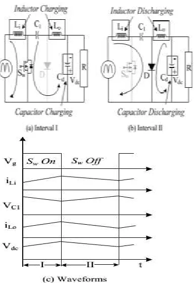
The operation of Cuk converter in CCM is described as follows. Figs.3(a) and (b) show the operation of Cuk Converter in two different intervals of a switching period and Fig.3(c) shows the associated waveforms in a complete switching period.
In terv al I: When switch Swim turned on, inductor LI stores energy while capacitor C1discharges and transfers its energy to DC link capacitor C d as shown in Fig.3(a). Input inductor current iLi increases while the voltage across the intermediate capacitor VC1 decreases as shown in Fig3(c).
In terval II: When switch Swiss turned off, then the energy stored in inductor Lo is transferred to DC link capacitor Cd, and inductor Li transfers its stored energy to the intermediate capacitor C1 as shown in Fig.3(b). The designed values of Li, Lo and C1are large enough such that a finite amount of energy is always stored in these components in a switching period.
B. DICM (Li) Operation:
The operation of Cuk converter in DICM (Li) is described as follows. Figs.4(a)-(c) show the operation of Cuk converter in three different intervals of a switching period and Fig.4 (d) shows the associated waveforms in a switching period.
In terv al I: When switch Swim turned on, inductor Li stores energy while capacitor C1discharges through Switch Sw to transfers its energy to the DC link capacitor C d as shown in Fig.4 (a). Input inductor current iLi increases while the voltage across the capacitor C1 decreases as shown in Fig.4 (d).
In terval II: When switch Swiss turned off, then the energy stored in inductor Li is transferred to intermediate
capacitor C1 via diode D, till it is completely discharged to enter DCM operation.
In terv al III: During this interval, no energy is left in input inductor Li, hence current I Latecomers zero. Moreover, inductor cooperates in continuous conduction to transfer its energy to DC link capacitor Cd.
Fig.5. Operation of Cuk converter in DICM (Lo) during (a-c) different intervals of switching period and (d) the associated waveforms.
C. DICM (Lo) Operation :
The operation of Cuk converter in DICM (Lo) is described as follows. Figs.5(a)-(c) show the operation of Cuk converter in three different intervals of a switching period and Fig.5(d) shows the associated waveforms in a switching period.
In terv al I: As shown in Fig.5(a), when switch Swim turned on, inductor L stores energy while capacitor C1discharges through switch Sw to transfer its energy to the DC link capacitor Cd.
In terval II: When switch Swiss turned off, then the energy stored in inductor Li and Lo is transferred to intermediate capacitor C1and DC link capacitor Cd respectively. In terval III: In this mode of operation, the output inductor Lo is completely discharged hence its current iLo becomes zero. An inductor Li operates in continuous conduction to transfer its energy to the intermediate capacitor C 1 via diode D.
D. DCVM (C1) Operation:
The operation of Cuk converter in DCVM (C1) is described as follows. Figs.6(a)-(c) show the operation of Cuk converter in three different intervals of a s witching period and Fig. 6(d) shows the associated waveforms in a switching period.
In terv al I: When switch Swim turned on as shown in Fig.6 inductor L Is tares energy while capacitor C1discharges through switch Swto transfer its energy to the DC link capacitor Cd as shown in Fig.6 (d).
In terv al II: The switch is in conduction state but intermediate capacitor C1is completely discharged, hence the voltage across it becomes zero. Output inductor Lo continues to supply energy to the DC link capacitor. In terval III: As the switch Sw is turned off, input inductor LI starts charging the intermediate capacitor, while the output inductor Lo continues to operate in continuous conduction and supplies energy to the DC link capacitor.
IV. DESIGN OF A PFC CUK CONVERTER A PFC based Cuk converter fed BLDC motor drive is designed for DC link voltage control of VSI with power factor correction at the AC mains. The Cuk converter is designed for a CCM and three different DCMs. In DCM, any one of the energy storing elements Li, Lo or C1are allowed to operate in discontinuous mode whereas in CCM, all these three parameters operate in continuous conduction. The design and selection criterion of these three parameters is discussed in the following section. The input voltage Vs applied to the DBR is given as,
𝑉
𝑠(t)=|
𝑉
𝑚Sin (2
𝜋𝑓
𝐿t)|=|220√2 Sin (314t) |V
(1) Where Vm is the peak input voltage (i.e. √2Vs, Vs is the rms value of supply voltage), fL is the line frequency i.e. 50 Hz. The instantaneous voltage appearing after the DBR is as,𝑉
𝑖𝑛(t)=|
𝑉
𝑚Sin (wt)|=|220√2 Sin (314t) |V
(2) Where | | represents the modulus function. The output voltage, Vdc of Cuk converter is given as𝑉
𝑑𝑐
=
𝐷
(1−𝐷)
𝑉
𝑖𝑛
(𝑡)
(3)Where D represents the duty ratio. The instantaneous value of duty ratio, D(t) depends on the Input voltage appearing after DBR, Vin (t) and the required DC link voltage, Vdc.
Hence the instantaneous duty ratio, D (t) is obtained by substituting (2) in (3) and rearranging it as,
𝐷(𝑡) =
𝑉
𝑑𝑐𝑉
𝑖𝑛(𝑡)+𝑉
𝑑𝑐=
𝑉
𝑑𝑐|𝑉
𝑚𝑠𝑖𝑛(𝜔𝑡)|+𝑉
𝑑𝑐(4) The Cuk converter is designed to operate from a minimum DC voltage of 40V (Vdc min) to a maximum DC link voltage of 200V (Vdc max). The PFC converter of maximum power rating of 350W (P max) is designed for a BLDC motor of 251W (Pm) (full specifications given in Table I) and the switching frequency (fS) is taken as 20kHz. Since the speed of the BLDC motor is controlled by varying the DC link voltage of the VSI, hence the instantaneous power, Piatt any DC link voltage (Vdc) can be taken as linear function of Vdc. Hence for a minimum value of DC link voltage as 40V, the minimum power is calculated as 70W.
TA BLE I
SPECIFICATIONS OF A BLDC MOTOR
S.NO PARAMETERS
VALUES
1 No. of poles (P) 4 POLES 2 Rated power (PRATED) 251.3 W
3 Rated DC link voltage (VRATED) 200V
4 Rated torque (TRATED) 1.2 N-M
5 Rated speed (NRATED) 2000 RPM
6 Back Emf constant (kb) 78V/KRPM
7 Torque constant (kt) 0.74N-M/A
8 Phase resistance (RPH) 14.56 Ω
9 Phase inductance (LPH) 25.71mH
10 Moment of inertia (J) 1.3×10⁻⁴ N-M
TA BLE II
ELECTRONIC OUTPUT BASED ON THE HALL EFFECT SIGNAL:
HALL
SIGNALS
SWITCHING SIGNALS
H1 H2 H3 Sa1 Sa2 Sb1 Sb2 Sc1 Sc2
0
0
0
0
0
0
0
0
0
0
0
1
0
0
0
1
1
0
0
1
0
0
1
1
0
0
0
0
1
1
0
1
0
0
1
0
1
0
0
1
0
0
0
0
1
1
0
1
1
0
0
1
0
0
1
1
0
0
0
1
0
0
1
1
1
1
0
0
0
0
0
0
TA BLE III
DESIGN PARAMETERS IN DIFFERENT MODES OF OPERATION
SPECIFICATIONS VALUES
Supply voltage(V𝑠) Rated:220v ,(Universal Mains:85-270v)
DC Link
Voltage(Vcd) Rated:220v,(40v-200v) Power (P) Rated:350w,(70w-350w)
Switching
frequency(fs) 20khz
OPERATION Li Lo C1 Cd
CCM 2.5MH 4.3mH 0.66µF 220µF DICM(Li) 100µH 4.3MH 0.66µF 220µF DICM(Lo) 2.5Mh 70µH 0.66µF 220µF DCVM(C1) 2.5mH 4.3mH 9.1nF 220µF
V.HYSTERESIS CURRENT CONTROL OF INVERTER
Fig.7.Hysteresis Current controlled Inverter fed BLDC drive.
Fig.7 shows the block diagram of hysteresis current controller which will generate the gating signals for inverter. The input currents, ia, ib, ic are measured and compared with the reference currents, ia*, Ib*, Ic*. The error is fed to a comparator with a prescribed hysteresis band. Switching of the power semiconductor devices (S1 ON and S2 OFF) occurs when the current attempts to exceed a set value corresponding to the desired current. The reverse switching (S1 OFF and S2 ON) occurs when the current attempts to become less than ia ref. Hysteresis controller is simple to implement and produces a very good quality of waveform. . The drawback of this method is that the switching frequency does not remain constant but varies along different portions of the desired current.
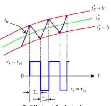
Fig.8.Iref and Iact given to Hysteresis current control The switching pattern is given as:
If ΔIa > H , S1 is on and S2 is off. If ΔIa < L , S1 is off and S2 is on. If ΔIb > H , S3 is on and S4 is off. If ΔIb < L , S3 is off and S4 is on. If ΔIc > H, S5 is on and S6 is off. If ΔIc < L, S5 is off and S6 is on.
Fig.9.Hysteresis Band switching.
adjusts the phase-current waveform to maintain ripple less electromagnetic torque, so that commutation torque ripples, particularly at high rotational speeds, are effectively eliminated. With the implementation of the proposed hysteresis current controller loop with current feedback loop and it is observed that there is a reduction in the current ripple hence torque ripple are minimized. Simulation analysis has been done to shows that current ripple and torque ripple are minimized which enhance the performance of the drive.
VI.M A TLAB/SIMULATION RESULTS:
Fig 10 Simulation model of BLDC motor drive fed by a PFC Cuk converter using a multiplier approach
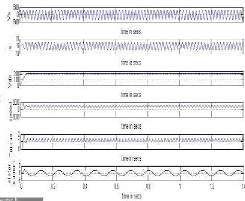
Fig.11.Simulation waveform for source voltage and current, dc voltage, speed, torque and armature current of the BLDC motor drive with the
Cuk converter operating in the CCM
Performance of BLDC Motor Fed Cuk Converter Op erating in the CCM:
The circuit configuration and control of the PFC Cuk converter operating in the CCM. The parameters selected for this converter to operate in the CCM are as follows: Input inductor Li = 2.5 mH, output inductor Lo = 4.3 mH, intermediate capacitor C1 = 0.66 μF and dc-link capacitor Cd = 2200 μF.
The performance of the proposed BLDC motor drive fed by a PFC Cuk converter operating in the CCM The input inductor current iLi, output inductor current iLo, and intermediate capacitor’s voltage VC1 are continuous in operation while the supply current Is is sinusoidal and in phase with the supply voltage vs. which shows a 0.9306 PF at ac mains.
Fig.12.Simulation waveform for source voltage and current, dc voltage, speed, torque and armature current of the BLDC motor drive with the
Cuk converter operating in the DICM (Li).
Fig.13.Simulation waveform for source voltage and current, dc voltage, speed, torque and armature current of the BLDC motor drive with the
Fig.14.Simulation wave form for source voltage and current, dc voltage, speed, torque and armature current of the BLDC motor drive with the
Cuk converter operating in the DCVM.
Simu lation model of CUK-converter fed HCC BLDCM d rive by using HCC:
Fig.15. Simulation model of HCC based BLDC motor drive fed by a PFC Cuk converter.
Fig.16.Control strategies for hysteresis current control.
Fig.17.Siumulation results for source voltage, current, dc link voltage, and speed, torque, stator current of BLDC motor under hysteresis
current control.
Performance of HCC based BLDC Motor Fed Cuk Co n verter:
Finally, a best suited mode of Cuk converter operating in CCM has been selected for experimental verifications . By using HCC the power factor is improved from 0.9306 to 0.9994.The simulation model which is implemented in a modular manner with HCC under MATLAB environment allows dynamic characteristics such as phase currents, rotor speed, and mechanical torque ripple has been effectively reduced.
Performance details:
S.NO
BLDC MOTOR
POWER
FACTOR
1 Fed CUK-converter 0.9306 2 fed CUK-Converter along withHCC
0.9994
VII.CONCLUSION
adaptability and strong robustness whenever the system is disturbed. By using HCC the power factor is improved from 0.9306 to 0.9994. The simulation model which is implemented in a modular manner with HCC under MATLAB environment allows dynamic characteristics such as phase currents, rotor speed, and mechanical torque ripple has been effectively reduced.
REFERENCES
[1] J. F. Gieras and M. Wing, Permanent Magnet Motor Technology—Design and Application. New York, NY, USA: Marcel Dekker, Inc, 2002.
[2] C. L. Xia, Permanent Magnet Brushless DC Motor Drives and Controls. Beijing, China: Wiley, 2012.
[3] Y. Chen, C. Chiu, Y. Jhang, Z. Tang, and R. Liang, “A driver for the singlephase brushless DC fan motor with hybrid winding structure,” IEEE Trans. Ind. Electron., vol. 60, no. 10, pp. 4369–4375, Oct. 2013.
[4] S. Nikam, V. Rallabandi, and B. Fernandes, “A high torque density permanent magnet free motor for in-wheel electric vehicle application,” IEEE Trans. Ind. Appl., vol. 48, no. 6, pp. 2287–2295, Nov./Dec. 2012.
[5] X. Huang, A. Goodman, C. Gerada, Y. Fang, and Q. Lu, “A single sided matrix converter drive for a brushless DC motor in aerospace applications,” IEEE Trans. Ind. Electron., vol. 59, no. 9, pp. 3542–3552, Sep. 2012.
[6] W. Cui, Y. Gong, and M. H. Xu, “A permanent magnet brushless DC motor with bifilar winding for automotive engine cooling application,” IEEE Trans. Magn., vol. 48, no. 11, pp. 3348–3351, Nov. 2012.
[7] C. C. Hwang, P. L. Li, C. T. Liu, and C. Chen, “Design and analysis of a brushless DC motor for applications in robotics,” IET Elect. Power Appl., vol. 6, no. 7, pp. 385–389, Aug. 2012. [8] T. K. A. Brekken, H. M. Hapke, C. Stillinger, and J. Prudell, “Machines and drives comparison for low-power renewable energy and oscillating applications,” IEEE Trans. Energy Convers., vol. 25, no. 4, pp. 1162– 1170, Dec. 2010.
[9] N. Milivojevic, M. Krishnamurthy, A. Emadi, and I. Stamenkovic, “Theory and implementation of a simple digital control strategy for brushless DC generators,” IEEE Trans. Power Electron., vol. 26, no. 11, pp. 3345– 3356, Nov. 2011. [10] T. Kenjo and S. Nagamori, Permanent Magnet Brushless DC Motors. Oxford, U.K.: Clarendon Press, 1985.
[11] J. R. Handershot and T. J. E Miller, Design of Brushless Permanent Magnet Motors. Oxford, U.K.: Clarendon Press, 2010.
[12] T. J. Sokira and W. Jaffe, Brushless DC Motors: Electronics Commutation and Controls. Blue Ridge Summit, PA, USA: Tab Books, 1989.
[13] H. A. Toliyat and S. Campbell, DSP-Based Electromechanical Motion Control. New York, NY, USA: CRC Press, 2004.
[14] “Limits for harmonic current emissions (equipment input current ≤16 A per phase),” International Standard IEC 61000-3-2, 2000
[15] N. Mohan, T. M. Undeland, and W. P. Robbins, Power Electronics: Converters, Applications and Design. New York, NY, USA: Wiley, 2009.
G urava Reddy Boreddy received B.Tech Degree in Electrical and Electronics Engineering from Visakha Institute of Technology and Science, Sontyam, Visakhapatnam, India in 2012 and currently pursuing M.Tech in Dadi Institute of Engineering and Technology, Anakapalli, Visakhapatnam, India. His fields of interest include Power Electronics, and Electrical M achines.
M .R.Prasad received B.Tech degree in Electrical and Electronics Engineering from Gokul institute of Technology and sciences, Bobbili, Andhra Pradesh, India in 2011 and his M.tech degree from Lakireddy Balireddy college of Engineering, Vijayawada, Andhrapradesh, India in 2015.He is currently working as Assistant professor in Dadi Institute of Engineering and Technology, since Jun 2016.his areas of interests are Distributed Energy Systems and Power flow in Micro grids.