ABSTRACT
KANG, SANGYEOL. Memory Allocation for Real-Time Embedded Systems. (Under the direction of Alexander G. Dean.)
c
Copyright 2012 by Sangyeol Kang
Memory Allocation for Real-Time Embedded Systems
by Sangyeol Kang
A dissertation submitted to the Graduate Faculty of North Carolina State University
in partial fulfillment of the requirements for the Degree of
Doctor of Philosophy
Computer Engineering
Raleigh, North Carolina
2012
APPROVED BY:
Eric Rotenberg Yan Solihin
Frank Mueller Alexander G. Dean
DEDICATION
BIOGRAPHY
ACKNOWLEDGEMENTS
TABLE OF CONTENTS
List of Tables . . . vii
List of Figures . . . .viii
Chapter 1 Introduction . . . 1
1.1 Memory Systems of Real-Time Embedded Systems . . . 1
1.2 Timing Variability . . . 4
1.3 Outlines . . . 6
1.4 Contributions . . . 7
Chapter 2 Review of Related Work . . . 12
2.1 Program Component Allocation into SPM . . . 12
2.1.1 Program Code . . . 13
2.1.2 Program Data . . . 14
2.2 Timing Predictability of Cache Memory . . . 21
2.2.1 Bounding of Cache Misses . . . 21
2.2.2 Improving Predictability of Cache Memory . . . 23
Chapter 3 Stack Split . . . 25
3.1 Introduction . . . 25
3.2 Stack Frame Models . . . 26
3.2.1 Original Stack Frame Model . . . 26
3.2.2 New Stack Frame Model by Stack Split . . . 28
3.3 Stack Frame Splitting Schemes . . . 29
3.3.1 Default Split and Dense Split . . . 29
3.3.2 Concerns in Real World Application . . . 30
Chapter 4 Data Allocation with Real-Time Scheduling . . . 33
4.1 Introduction . . . 33
4.2 DARTS Concept . . . 33
4.2.1 DARTS Cycle . . . 34
4.2.2 Memory Access Time and Data Allocation . . . 36
4.3 Experiments . . . 41
4.3.1 Taget System . . . 41
4.3.2 Experiment Setup . . . 43
4.4 Results . . . 44
4.4.1 Single-Task Perspective Discussion . . . 45
4.4.2 Multi-Task Perspective Discussion . . . 49
Chapter 5 Extracting Synergy between Scratchpad Memory and Data Cache 53
5.1 Introduction . . . 53
5.2 Motivating Example . . . 54
5.3 Allocation of Data into SPM . . . 57
5.3.1 Intrinsic Misses and Interference Misses . . . 57
5.3.2 Allocation Scheme – Exhaustive Search . . . 60
5.3.3 Allocation Scheme – Heuristics . . . 61
5.4 Experiments . . . 62
5.4.1 Target System . . . 62
5.4.2 Experiment Setup . . . 64
5.5 Results . . . 69
5.5.1 Allocation at Coarse Granularity Level . . . 69
5.5.2 Allocation at Fine Granularity Level . . . 73
5.6 Summary . . . 76
Chapter 6 Balancing Scratchpad Memory and Data Cache for Synergy . . . . 78
6.1 Introduction . . . 78
6.2 ILP-based SPM Allocation . . . 79
6.2.1 Basic ILP Formula . . . 79
6.2.2 ILP Formula Embedding Call Graphs . . . 82
6.3 Memory Access Distribution and SPM Performance . . . 84
6.3.1 Memory Access Concentration . . . 85
6.3.2 Performance of ILP-based SPM Allocation . . . 86
6.4 Experiments . . . 90
6.4.1 Target System . . . 90
6.4.2 Experiment Setup . . . 91
6.5 Results . . . 92
6.5.1 Memory Access Performance . . . 92
6.5.2 Dynamic Energy Consumption . . . 95
6.5.3 Comprehensive Perspective Discussion . . . 98
6.6 Summary . . . 100
Chapter 7 Summary and Future Work . . . .101
LIST OF TABLES
Table 4.1 Target hardware system features and toolchain . . . 42
Table 4.2 Properties of tasks used for experiments . . . 42
Table 4.3 Speedup comparison between DARTS (using 2-cycle SPM) and 1-cycle data cache . . . 50
Table 5.1 Target hardware system features and toolchain . . . 63
Table 5.2 Test programs used for experiments . . . 64
Table 5.3 Cache contention degree table used in fine granularity level experiments . 67 Table 5.4 Number of scheduler ticks encountering by MgSort andRotate . . . 69
Table 5.5 Best task combinations allocated into SPM and corresponding cache misses counts from coarse granularity level experiments (Controlled-Allocation) . 69 Table 5.6 Best task combinations allocated into SPM and corresponding cache misses counts from coarse granularity level experiments (Real-Allocation) . . . 71
Table 5.7 Portion of memory access counts and intrinsic cache miss counts by each task during hyperperiod . . . 72
Table 5.8 Best combinations under limited SPM capacity at coarse granularity (Controlled-Allocation) . . . 73
Table 5.9 Best combination under limited SPM capacity in fine granularity level experiments (Controlled-Allocation) . . . 74
Table 6.1 Memory access distributions used in simulation . . . 86
Table 6.2 Test programs used for evaluation and experiments . . . 90
Table 6.3 Memory parameters used for evaluation . . . 91
Table 6.4 Cache miss rate and SPM allocation saturation point of test programs . . 94
Table 6.5 Hybrid configurations showing best memory access performance . . . 98
LIST OF FIGURES
Figure 1.1 Static RAM cell consisting of six transistors [81] . . . 2
Figure 1.2 Simplified structures of two fast memory systems . . . 3
Figure 1.3 Adjusted CPU utilization bounds for rate monotonic scheduling . . . 5
Figure 3.1 Example code and stack frames . . . 27
Figure 3.2 Pseudo code of stack split (dense split) . . . 31
Figure 4.1 DARTS application flow and components provided by toolchain . . . 34
Figure 4.2 Example of preemption graph embedding call graphs inside . . . 35
Figure 4.3 Memory footprint of data objects at task, procedure and variable level . 37 Figure 4.4 Performance comparison ofADPCM . . . 45
Figure 4.5 Performance comparison ofHuff . . . 46
Figure 4.6 Performance comparison ofMgSort . . . 47
Figure 4.7 Performance comparison ofDijkstra . . . 48
Figure 4.8 Performance comparison ofSHA . . . 49
Figure 4.9 Improved real-time performance . . . 51
Figure 5.1 Sensitivity of data cache performance in single-threaded system . . . 55
Figure 5.2 Example of new cache miss analysis . . . 60
Figure 5.3 Cache contention degree graph used in coarse granularity level experi-ments (in Rotate-centric view) . . . 65
Figure 5.4 Cases of negative interference miss counts . . . 68
Figure 5.5 Reduction of cache misses by SPM allocation using heuristic I and other methods on exhaustive search from coarse granularity level experiments . 70 Figure 5.6 Reduction of cache misses by SPM (1KB) allocation into using heuristic I and exhaustive search at fine granularity level . . . 73
Figure 5.7 Correlation of actual cache performance vs. cache contention degree estimated by heuristic II and SPM usage (Controlled-Allocation) . . . 75
Figure 6.1 Call graph to obtain example call graph matrix Geg (SHA[30]) . . . 84
Figure 6.2 Captured memory access distributions . . . 85
Figure 6.3 Diminishing returns of memory access performance by ILP-based SPM allocation . . . 87
Figure 6.4 Performance estimation of hybrid configuration of SPM and data cache . 89 Figure 6.5 Fraction of SPM access counts to first level memory access counts . . . . 93
Figure 6.6 Diminishing returns as increasing SPM capacity with 8KB data cache . . 94
Figure 6.7 Memory access performance of various hybrid configurations from esti-mation and simulation . . . 96
Figure 6.8 Dynamic energy consumption of various hybrid configurations from es-timation . . . 97
Chapter 1
Introduction
1.1
Memory Systems of Real-Time Embedded Systems
As technology evolves, more power is available to computer systems, including embedded sys-tems. Development of faster, more powerful and more versatile embedded devices has not paused. As a reaction to this achievement in modern technology, designing computer systems becomes further complicated. Design engineers of computer systems are asked to balance per-formance and cost in spite of ever-increasing complexity. Developing embedded systems involves more complexity since the system resources are likely to be limited, but manufacturing cost is sensitive to even small changes in the design. Design engineers of real-time embedded systems especially must take one more challenging design factor into consideration on top of the others, which is real-time schedulability .
Processors and memory systems are the major components in modern computer systems. Processors manipulate information and the memory stores the information, such as program code and data, to keep the computation continual. System performance depends on the perfor-mance of these components. However, a perforperfor-mance gap exists between processors and memory systems [34] and many researchers have been encouraged to brdige the gap in tremendously novel ways.
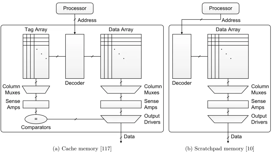
Cache memory and scratchpad memory (SPM) are a marvelous idea in this sense. These two types of memory system provide small but quickly accessible memory space near to the processors so that the processors can reduce access time to the code and data. Both cache memory and SPM have static RAM cells consisting of 6 transistors to store their contents, as in Figure 1.1 [81]. However, they are different in architectural aspects, and the different hardware schemes are naturally related to different control mechanisms and characteristics. Figure 1.2 depicts two fast memory systems [117, 10].
cir-Figure 1.1: Static RAM cell consisting of six transistors [81]
cuitry such as sense amplifiers, output drivers and so on. The cache memory is not assigned to a part of system’s address space particularly but covers all cacheable memory accesses. Con-tents of the cache memory are loaded and replaced automatically by the hard-wired algorithm. Recently used contents and their neighboring contents are cached since they are more likely to be requested by the processors. These temporal and spatial localities of the code and data are utilized to enhance the cache performance whilst overcoming its limited capacity. Hence, the cache memory takes advantage of multi-level memory systems covering all cacheable memory access automatically.
(a) Cache memory [117] (b) Scratchpad memory [10]
Figure 1.2: Simplified structures of two fast memory systems
Scratchpad memory (SPM) has been regarded as an alternatively faster memory in place of the cache memory in real-time embedded systems. SPM is a fast on-chip memory located near to the processors whose memory cell is similar to that of the cache memory. The difference is that it does not have hardware controllers such as the tag array or control logic supporting tag matching to load and evict the contents automatically (as the cache memory does). Consequently SPM consumes less energy per access. SPM has its own address space, which is part of the system address space. The SPM contents are controlled by software and SPM responds to memory access only within itself. Thus, SPM takes advantage of heterogeneous memory systems and has versatile functionality managed by software methods.
mechanism burdens the programmers with content selection, and content selection affects the system performance directly. Furthermore, the embedded systems are equipped simultaneously with heterogeneous memory units whose characteristics such as access latency, access bus width, and energy consumption are diverse. Therefore, researchers have developed various schemes to select and manage the SPM contents for the best performance.
Wise and efficient memory allocation for real-time embedded systems is not straightforward but also cannot be overlooked. To improve system performance, the cache memory may be used, but the system suffers from the timing variability. SPM may be used to replace cache memory, but the programmers are responsible for choosing the most beneficial data on behalf of the system, considering many factors. This study looks into data allocation problems in real-time embedded systems using SPM and data cache memory, and those with solely SPM. Ultimately this study aims to investigate memory allocation methods enhancing real-time em-bedded systems beyond many conflicting design factors, including memory access performance, energy consumption and timing predictability.
1.2
Timing Variability
Timing variability makes developing a real-time embedded system difficult since it directly impedes timing analysis, which is an essential design step to guarantee schedulability of the system. There are many sources of timing variability and timing noise in contemporary em-bedded systems, such as out-of-order execution, speculation techniques in processor pipelines, non-uniform memory access latency and so on [60, 33, 112]. Behaviors of these features are so dynamically changing that it is not easy to estimate the behaviors by tightly bounding. Even if the timing analysis is performed appropriately, the system is likely to be over-provisioned to give more timing margin for schedulability.
One example helps us understand the impact of timing variability to a system’s schedula-bility. Let a target system schedule n tasks in a rate monotonic way. In order for the system to work properly in the rate monotonic scheduling, a CPU utilization test must meet the the-oretical upper bound, which is given in Equation 1.1 [56, 57]. A task i’s period is given as Ti
and its execution time is Ci.
U ≤n
2n1 −1
where U =
n
X
i=1
Ci
Ti
(1.1)
Now consider a new CPU utilization which is composed of two parts: analyzable part Ua
and timing variable part Uv. The analyzable part can be calculated or analyzed statically so
5 10 15 20 25 30 35 40 45 50 0
0.1 0.2 0.3 0.4 0.5 0.6 0.7 0.8 0.9 1
CPU Utlization
Number of Tasks
Original δ=0.001 δ=0.002 δ=0.003 δ=0.005 δ=0.010
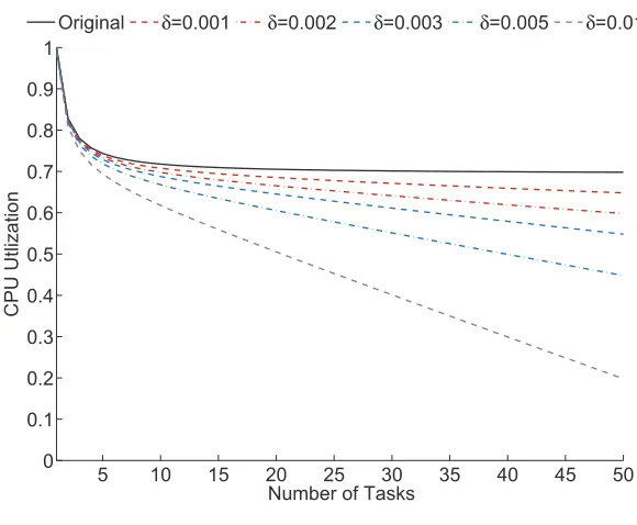
Figure 1.3: Adjusted CPU utilization bounds for rate monotonic scheduling
phase. The actual CPU utilization becomes the sum of the two parts, as shown below, when timing variation is introduced into each task of the system by ∆i.
U =Ua+Uv
=
n
X
i=1
Ci
Ti
+
n
X
i=1
∆i
Ti
(1.2)
Provided simply that the timing variation is uniformly rated for all the tasks by δ of their periodTi respectively, i.e., ∆i =δTi. Then,
Uv =nδ (1.3)
When the system is designed, Uv is not expected but actually imposed onto the system
during its running. Hence, in order to guarantee the feasibility of the system, a new utilization test must be considered as in Equation 1.4, whose upper bound is less than that of the original in Equation 1.1.
Ua≤n
21n −1
−nδ (1.4)
The topmost black solid line plots the original upper bound from Equation 1.1, and other lines show the adjusted bounds corresponding to Equation 1.4. As observed in the plots, realistic upper bounds are less than the original one. For example, when the timing variability of each task is 1% of its period (δ= 0.010) in the system running 10 tasks (n= 10), it is observed that the gap between the original bound and the adjusted one is 10%. Furthermore, as the timing variability increases so that δ also increases, more timing margin is required. This situation gets worse as more tasks run on the system. Although this calculation is based on slightly over estimated parameters and simplified assumptions, the impact of the small timing variability to the system is demonstrated well in the plots.
The above example addresses rate monotonic scheduling, which is one static priority schedul-ing method. A system acceptschedul-ing dynamic priority schedulschedul-ing also suffers from the same problem. For example, sucess of the earliest-deadline-first (EDF) scheduling [56] or the least slack time (LST) scheduling [64] also leans on tasks’ actual execution time or estimation of the execution time. Hence, unexpected timing variability makes the system design difficult because: (1) it is not estimated or analyzed easily and (2) it requires more conservative and over-provisioned design.
1.3
Outlines
As described in the previous sections, needs for better performance and safer real-time behavior in real-time embedded systems necessarily intersect at providing fast but timing predictable memory systems. Since huge efforts have been already made on SPM and cache memory, part of the research in diverse fields which have motivated, inspired and informed this study are briefly reviewed in Chapter 2. We look through research addressing SPM allocation methods of program code and data, and management methods of the SPM contents. Efforts to improve timing predictability of cache memory are also reviewed.
One challenging job after obtaining a new data allocation is implementing the data allocation to a target system so that we can actually use it. When automatic data variables are moved to different memory units apart from their original locations, original stack frames containing the variables may no longer be maintained within their original memory unit. Chapter 3 proposes stack split, an assembly rewriting technique to deploy the procedure stack frames across multiple
memory units at a fine granularity level. The stack split technique is actually applied for the DARTS implementation discussed in Chapter 4.
platform. Chapter 4 extends the DARTS method toward a full implementation under further realistic circumstances. The allocation method is transplanted to the popular ARM processor platform. Real test benchmarks are examined to evaluate the scheme with the help of the stack split scheme on real hardware. Memory access performance obtained from DARTS is comprehensively compared to that of real data cache hardware.
This study leverages SPM to improve data cache performance beyond taking its alternative benefits (such as fast access latency and better timing predictability) to data cache. Allocating some parts of data into SPM reduces cache contention by the data and finally improves the cache performance. Of course, the data stored in SPM do not experience any performance degradation. This interactive benefit is recognized assynergy between SPM and data cache in Chapter 5. The chapter also proposes synergetic SPM allocation heuristics, which can alleviate inter-data cache contention of tasks and cache misses in multi-threaded preemptive real-time embedded systems. For this, a new concept of cache miss analysis is also proposed, where we classify cache misses intointrinsic misses and interference misses.
A question about how to balance limited hardware resources (e.g. die area or fast memory capacity) between the two fast memory systems remains unanswered after discussing the syn-ergetic SPM allocation scheme. Chapter 6 empirically investigates ways to expand the synergy by balancing the hybrid configurations of SPM and data cache in aspects of memory access latency, data cache performance, dynamic energy consumption and energy-access latency prod-ucts. Various hybrid configurations of SPM and data cache are simulated and and evaluated with those metrics. The chapter also observesconcentration of memory access to a small por-tion of data variables, which leads to diminishing returns as SPM capacity increases. Some guiding insights established from the simulation and evaluation results are supported by those observations.
To summarize, the hybrid configuration of SPM and data cache are studied in Chapter 5 and 6, and the memory configuration using only SPM is explored in Chapter 4. Chapter 3 explains a supporting technique to exploit SPM for automatic type stack variables. This chapter (Chapter 1) introduced this study with examples of the timing variability problem in the real-time embedded systems, compared SPM to data cache qualitatively, and discussed outlines and contributions. Chapter 2 introduces related research work briefly. Chapter 7 summarizes all chapters and lists future work beyond the findings of this study.
1.4
Contributions
Throughout all the chapters as outlined above, this study demonstrates several contributions distinguishing itself from the prior achievements by other researchers reviewed in Chapter 2.
targeting real-time embedded systems. Most of the SPM allocation studies compare benefits such as memory access performance, estimated worst case execution time (WCET), energy saving or die area when using SPM to those metrics when using cache memory [5, 37, 10, 95, 94, 21, 112, 61, 1, 77]. Those studies regard SPM as an alternative to cache memory. Only a few studies investigate the hybrid configuration consisting of SPM and cache memory [20, 108, 110, 76, 75]. Mamidipaka et al. also report some benefit in data cache access counts after employing the on-chip stack memory [62]. Other studies propose cache locking and cache partitioning [46, 47, 79, 78, 80, 102, 103] in order to improve timing predictability of cache memory directly. Little work has promoted SPM to enhance cache memory, and relatively less attention has been paid to the synergy between SPM and cache memory, even though hybrid configurations can provide better performance with little timing variability.
The work presented in Chapter 5 [42] differs from all these studies in several ways: (1) our proposed schemes take advantage of both SPM and cache memory, rather than one or the other, in order to mitigate inter-data cache pollution while still providing fast memory access for all data, (2) this study presents a new approach toward data cache miss analysis, which guides a way to identify data to allocate into SPM, (3) the allocation schemes are thus based on the new data cache miss analysis rather than data access count analysis or data access frequency analysis in multi-threaded real-time embedded systems, and (4) our work considers data allocation and data cache rather than instruction allocation and instruction cache; where cache behavior is ever-changing, and analyzing it involves much more complexity. In other words, this study reports the synergy between SPM and data cache that exists in memory access performance, which can be extracted via the new cache miss analysis concept and the allocation heuristics proposed in this work.
As a next step in studying this synergy, Chapter 6 establishes several other differences be-tween this work and current research: (1) it discovers that a small portion of data variables generate a large amount of data memory access counts, (2) the concentrated memory access distributions are modeled with exponential distributions and simulated to show the diminishing returns as SPM capacity increases due to the concentrated memory access, and (3) various hy-brid configurations of SPM and data cache are evaluated by four metrics: total memory access latency, total data cache miss counts, total dynamic energy consumption and energy-access latency products. To summarize, this work is the first work which reveals that performance benefit attainable from SPM is correlated to the memory access distribution, and the benefit diminishes as SPM capacity increases. The chapter also reports that the synergy can be esca-lated at certain balanced capacities between SPM and data cache and establishes some guiding insights on employing the hybrid fast memory configurations from all these observations.
units, automatic type data organized in the stack frames can be managed at two different granularity levels, one at an entire procedure stack frame level [17, 77, 22, 88] and another one at an individual data object level [8, 9, 23, 25, 101]. Both the approaches induce large runtime overhead since they employ a dynamic SPM management scheme (explained in Chapter 2) or require fastidious attention on implementation since the traditional stack frames are not designed for a situation using the multiple frames.
This study proposes the stack split technique, which is a viable stack frame splitting ap-proach and toolchain support described in Chapter 3 [41]. The proposed method is novel in several ways: (1) the stack split method is an assembly rewriting technique rather than a tech-nique adjusting stack pointer values or requiring hardware support, (2) this approach enables fine-grain use of the SPM for stack access without the help of compilers, while preserving the stack-based allocation of the automatic variables, (3) overhead is not large (under 20 clock cycles per additional stack pointer in our implementation) since only several additional instruc-tions are inserted per procedure, and (4) it implements a static SPM management method but automatically supports dynamic management of the SPM contents thanks to the innate properties of the stack frames. To summarize, the stack split scheme maintains the dynamic stack-based allocation/deallocation nature of automatic variables through assembly rewriting. The method provides efficient memory use, and this is especially valuable for SPM since its size is limited.
toolchain allocating data automatically to SPM, applied the new allocation to real programs, and measured real performance on a real hardware system. This work evaluates the performance benefit of DARTS with a real target system having an ARM processor core and a preemptive real-time operating system modified to support thepreemption threshold scheduling. Automatic type data are deployed into SPM by the stack split technique. Test programs having all types of data access and larger data sets are experimented, which diminishes the benefit since dynamic type data are not handled optimally by the current version of the toolchain. This study shows that the suggested method may be stronger since performance is improved significantly even under those realistic circumstances with some constraints.
This study discusses the synergy when using the hybrid configuration of SPM and data cache (Chapter 5 and 6) as well as the sole configuration of SPM (Chapter 4) in real-time embedded systems. The synergy can be explained qualitatively; allocating code and data into SPM increases the effective capacity of cache memory without performance loss. Then, residual code and data can take advantage of the larger cache capacity with less contention. This improves the cache performance and eventually system performance with little timing variability by memory access. Particularly the discussion on the hybrid configuration aims at verifying two hypotheses: (1) allocating data variables into SPM employs some synergy in memory access performance by improving data cache performance, and (2) the synergy is escalated at a certain balanced capacity between SPM and data cache.
Regarding these hypotheses, several points are articulated here; the discussion in Chapter 5 and 6 does not address directly how the synergy improves the worst case performance or the worst case performance analysis which is considered critically when designing hard real-time embedded systems. The chapters lack of the worst case timing analysis but focus on average case performance, when SPM and data cache are provided simultaneously, although such worst case timing studies remain a proposed direction for future study. This study also does not claim that SPM always fits better for real-time embedded systems. As long as cache misses can be bounded safely by the static cache miss analysis methods introduced in Chapter 2, our target systems can be designed feasibly in the real world. This work does not claim that SPM always outperforms cache memory since we do not explore design space for choosing the most beneficial cache parameters.
energy consumption by SPM is much less than that of data cache, and many modern systems are equipped with SPM and data cache at the same time. Therefore, recognizing and balancing the synergy between SPM and data cache are worth exploring.
The contributions of this study can be summarized as follows:
• This study reveals performance synergy between SPM and data cache. A novel cache miss
analysis concept – intrinsic miss and interference miss – and SPM allocation heuristics are suggested to accommodate the synergy for multi-threaded preemptive real-time embedded systems.
• This study discovers that the memory access of data variables are concentrated to a small
portion of the data variables, and this distribution leads to diminishing returns as SPM capacity increases. This phenomenon establishes guiding insights to balance the synergy between SPM and data cache memory in various hybrid configurations.
• This study proposes stack split, an assembly rewriting scheme, to deploy the traditional
stack frame of procedures across multiple memory units with small runtime overhead.
• This study extends data allocation with real-time scheduling (DARTS) to a full and
Chapter 2
Review of Related Work
2.1
Program Component Allocation into SPM
Allocating program components efficiently into SPM has been actively studied so far. Several orthogonal bases can categorize the existing research achievements into several groups. Pro-gram code and data are allocated into SPM either separately or together. Some work targets multi-threaded systems, while other work focuses on single-threaded systems. Some studies consider cache memory along with SPM into their SPM allocation process, while other studies do only SPM. Management methods of the SPM contents also categorize the work. However, regardless which allocation method is accommodated across all these categories, timing pre-dictability of memory access is improved since the program components serviced by SPM are recognized predictably. Especially the two different management methods of the SPM contents are explained here since later parts of this section divide the already existing research studies by the SPM management methods they address as well as by other factors.
One method calledstatic management locates and loads the SPM contents statically before a target system starts running and does not update the SPM with new contents once it is loaded. This method is not concerned with how to replace the SPM contents during the execution of a program. It lacks extra code to manage the SPM contents dynamically. Hence, the static method imposes no extra code execution and very low runtime overheads on target systems. But this method utilizes the SPM space less by limiting exploitation of spatial and temporal reuse patterns of the program components, since the SPM contents reside in fixed locations until end of the program’s execution.
locality of the program code and data for some given SPM capacity. The dynamic method is usually more flexible than the static method at the cost of much higher run-time overheads, and the overheads increase as more components are allocated into SPM. Furthermore, if the loading cost of some components is larger than performance benefit, the components have no reason to allocate into SPM even though SPM space is available.
2.1.1 Program Code
Access patterns to program code are more regular than access patterns to data. Multiple instructions unite to a basic block, one large execution block where the program’s control flows on straight. The control flow changes only on branches, jumps, function calls and returns. In most cases, these changes in control flow head toward instructions whose addresses are known explicitly. This regularity of the access pattern promotes allocation of the program code into SPM.
One stem of work in this field [4, 5, 108, 110] takes the static approach, and another one [94, 20, 37, 97] takes the dynamic approach. Egger et al. considers both of the management methods at the same time in one of their studies [19]. In addition to all these studies, one body of work [10, 95, 107, 109, 106, 72, 73] manipulates both the program code and data, which is discussed in Section 2.1.2.
Angiolini et al. modeled the SPM allocation problem of program code into SPM to some dynamic programming problems [4, 5]. Their former work [4] performed the SPM allocation by synthesizing partitioned SPMs for particular target applications, as several other studies did [13, 12, 11]. However, this method restricts its applicability to other applications since the SPMs are synthesized only for some particular applications, and source code analysis is required for synthesizing the best partitioned SPMs. Their later work [5] widened the applicability by employing a patching tool, which modifies selected executable code segments at a post-compiler stage, connecting execution of the instructions in SPM and in the main memory. Although this work focused on code allocation and did not consider cache memory actively, several hybrid configurations of SPM and instruction cache were examined. Their simulation results alluded to some performance synergy between SPM and the instruction cache, which is described in Section 5 and 6 of this study.
approach.
Steinke et al. moved instructions (basic blocks) into SPM dynamically by inserting copier functions to original source code [94]. Their proposed algorithm selects target instructions copied into SPM and possible positions of the copier functions by comparing the copying cost. The final selection of the instructions is performed by solving the 0-1 Knapsack Problem based on ILP formulas. Their simulation results show that SPM performs better than cache memory in both performance and energy saving.
Egger et al. modeled code selection problems by the 0-1 Knapsack Problems for performance improvement and energy saving [19, 20]. One of their studies [19] classified code blocks into three categories: ones in SPM statically, other ones in DRAM statically and the others paged dynamically between SPM and DRAM. This work implemented an on-demand paging manager and modified executable binary to call the paging manager at a post-compiler stage. Their other work [20] also categorized the program code into three different groups: uncached, cached and paged. In this work, only the paged code blocks are loaded into SPM on demand, and the cached blocks are supported by a mini instruction cache. The on-demand page loading takes advantage of virtual memory environments [35], and this work is the first approach to access physically-indexed SPM in virtual memory environments. Although these studies are different from each other in terms of SPM management, both methods support machine binary modification techniques, which expands the applicability of the methods since no source code is required.
Janapsatya et al. copied program code dynamically into SPM [37] by using special custom instructions suggested in their previous work [36]. Two metrics called concomitance and self-concomitance capture probabilities of two code blocks, including a duplicated single basic block, and are executed in a temporally correlated manner. Selection of the basic blocks is based on these metrics.
Suhendra et al. presented a method supporting dynamic allocation of code into SPM for preemptive, multi-tasking embedded systems (potentially with multiple processors) to mini-mize the worst case response time [97]. A chart called the Message Sequence Chart (MSC) captures the sequence of communications between the processes. An iterative analysis on the MSC identifies disjoint lifetimes of the processes and the variables within the processes. These variables can share the same SPM locations.
2.1.2 Program Data
discussion of the data variable type, the static management methods [76, 75, 10, 95, 107, 112, 89, 90, 8, 9, 23, 25, 72, 96] are reviewed first and the dynamic management methods [39, 38, 40, 100, 101, 109, 106, 21, 51, 16, 115, 116] follow.
In one example of early work in this field, the partitioning of scalar and array variables to SPM and data cache was studied by Panda et al. [76, 75]. Their work is close to this study in the sense that SPM and data cache are considered actively at the same time. The former work [76] focused on a single program system, and the later work [75] extended to cover multiple levels of memory hierarchy and context-switching of multiple programs, although the context-switching is emulated as randomly switching memory traces of three tasks. These works aim at minimizing cross-interference between different scalar and array variables by using several metrics reflecting the variable’s lifetime, size, access frequency, and potential cache conflicts inside of loops. The potential cache conflicts were estimated statically and loosely by examining the program source code for array accesses. All of this information is required a priori for the allocation process. The synergy between SPM and data cache was partially reflected in their experimental results, such as execution time and external memory access counts.
To our best knowledge, one study by Banakar et al. [10] and another study by Steinke et al. [95] are the first trials which compared performance and energy consumption by SPM to that of cache memory. The former work [10] used circuit models provided by CACTI [117] to estimate memory cell area, energy consumption and performance of SPM and cache memory. The selection algorithm of SPM contents was demonstrated in the other work [95], which detailed the algorithm to reduce energy consumption by a program through extending a compiler. The energy consumption by program code and data was modeled into a 0-1 Knapsack Problem, and the most frequently accessed program components were selected for allocation into SPM. In some trace-based simulations, SPM was estimated to occupying less chip area, consuming less energy but achieving better performance.
One work by Verma et al. [107] extended the work by Steinke et al. [95] to enable maximal SPM usage. They partitioned array variables into smaller pieces so that the SPM usage could be improved at a finer granularity level. One study by Wehmeyer et al. [112] compared average case performance and WCET estimation of SPM equipped systems to those of unified cache equipped systems. They used the allocation algorithm suggested by Steinke et al. [95] and the energy consumption model demonstrated by Banakar et al. [10].
Some methods of Sj¨odin et al. [89] addressed the allocation of static variables (e.g. globals) with a greedy heuristic. Their later work [90] allocated both static type data and automatic type data (i.e. stack variables).
are close to DARTS [23, 25], in the sense that the lifetimes of the stack variables captured from the call graph is brought into the ILP formulas. However, the extended DARTS described in Chapter 4 considers the lifetimes of data objects at task level with the preemption graph and at the procedure level with the call graph together. Another similarity about maintaining multiple stack frames for one procedure is discussed later. One more interesting thing is that diminishing returns as SPM capacity increases is also observed in their result, although the authors do not mention this. This study investigates this phenomenon comprehensively in Chapter 6.
The allocation algorithm of Avissar et al. was used in two studies by Nguyen et al. [72, 73]. The authors proposed software loader routines to implement new data allocation into SPM, assuming the SPM size is unknown at compile time. The loader discovers the SPM size, selects program code, static data and automatic data, and finally modifies machine binary. The binary has been already compiled considering the modification by the loader routines. Hence, the loader routines stretch portability of the target applications toward different size SPMs, although source code of the application needs to be recompiled for this. One later study [73] extended the previous work by renaming the loader to the installer, detailing the SPM contents selection algorithms and addressing real world issues such as handling library and separate compiling.
Suhendra et al. optimized the allocation of data variables of the worst case [96] rather than those of the average case. Since the profiled information contains infeasible paths, a branch-and-bound search was suggested as well as two heuristics in order to reduce the running time of the search.
Ghattas et al. combined a real-time task scheduling scheme with a SPM allocation scheme, which is named to Data Allocation with Real-Time Scheduling (DARTS) [23, 25]. Unnecessary preemptions are disabled by Preemption Threshold Scheduling (PTS) [111, 85] to increase disjoint lifetimes of automatic type data variables at task level. This, in turn, increases SPM utilization further since those data variables can share the same SPM space in an overlaid manner, as Suhendra et al. did [97]. It handles the data variables on the worst case execution path and multi-threaded real-time task scheduling through the proposed preemption graphs. All these are integrated into ILP formulas at a different granularity level of data. In their implementation, static variables are not managed dynamically so that the runtime overhead to manage them in the dynamic management scheme is avoided. Distributed procedure stack frames across multiple memory units implemented the dynamic management scheme due to the nature of automatic variables. However, they have evaluated the benefit of the scheme by simulating randomly synthesized workloads and targeted the AVR 8-bit processor platform.
filed applications such as image and video processing [39, 38, 40]. One part of the work [39, 40] decomposed the arrays into tiles so that the arrays could be loaded partially into the small size of SPM. They suggested a series of compiler techniques to partition the SPM space, generate loop access patterns using the tiles, and restructure program code for the data transfer. In another study [38], the authors suggested a different compiler technique, leaning on the reuse vector and matrix for multi-level SPM hierarchy. They proposed their upgraded compiler could be used when designing new SPM hierarchies from applications as well when allocating for already existing hierarchies.
Udayakumaran et al. also suggested dynamic SPM management methods supported by compilers [100, 101]. A profile-driven cost model supported by the compilers identifies possible program points such as functions, conditionals or loops entries and exits into which data transfer code can be inserted. The Data Program Relationship Graph (DPRG) associates timestamps to the program points of interest to determine lifetime of the SPM contents. From this analysis, the most promising data are selected by a greedy heuristic. Their later work [101] extended this approach to present actual SPM layout and code generation methods. However, implemen-tation of the new SPM allocation is performed through indirect methods since stack variables were converted into global type variables. For the global variables, extra variable symbols are inserted, which copy their original values when they are about to be accessed in SPM. (This implementation method is discussed in more detail together with Avissar et al.’s scheme later.) Udayakumaran et al.’s work overcomes limitations of the work by Kandemir et al. [39, 40]. Kandemir et al. limited their study to well-structured loop nests. But Udayakumaran et al. worked with a fully general dynamic method covering global and stack variables. Furthermore, they supported a whole-program analysis across all control structures, while Kandemir et al. manipulated each loop nest independently.
Verma et al. applied a global register allocation scheme [15, 29] for SPM allocation that overlays multiple program components onto the same SPM space [109, 105]. Live range analysis on profiled program information identifies the overlaying SPM contents. For better utilization of SPM, the ILP formulas finally determine the SPM contents, and inserted SPM spilling code manages the SPM contents dynamically. However, the work lacks explanation of practical implementation methods for new allocation, such as how to assign the same memory address to multiple memory objects and how to handle branch instructions. Another work by Verma et al. [106] suggested methods for sharing SPM space with multiple processes for energy saving, although only round-robin static scheduling was assumed. They examined three different SPM management schemes: partitioned and exclusively assigned to a process, non-partitioned and fully shared by all the processes, and hybrid types of the two methods.
can reduce data transfer cost from main memory to SPM. To make the DMA-based data transfer easier, software application programming interfaces (API) are also supported at high level language. They simulated performance and energy consumption, and their management scheme outperforms explicit data transfer schemes inserting copier function into code. However, program source code needs to be rewritten with the APIs in order to apply this scheme.
Li et al. proposed a compiler technique called memory coloring to allocate data arrays into SPM [51]. In their scheme, SPM is partitioned to pseudo registers having predefined sizes, and live ranges of the data arrays are analyzed and split to fit the SPM partition. Then, register allocation algorithms based on Graph Coloring [15] maps the partitioned SPM to the data arrays. Some data transfer code is also inserted.
Deverge et al. managed both static type and automatic type data variables in SPM dy-namically to reduce a single task’s WCET [16], while Suhendra et al. used a static method for the same purpose [96]. Hence, their experimental evaluation involved modifying compilers to generate executable code, including data transfer code, to analyze timing of tasks, and to adjust a task’s resulting timing by compensating the data transfer cost. They also managed pointer-referenced memory access.
Although much research has allocated static type and automatic type data into SPM, moving automatic type data variables into SPM is not straightforward. The automatic type data variables of a procedure are located in a stack frame of the procedure, and the traditional stack frame is organized by compilers which are not aware that the stack frames can be deployed across multiple memory units. Several studies [8, 9, 62, 77, 23, 25, 22, 88] paid attention to this problem.
Avissar et al. proposed splitting stack frames across different memory units [8, 9]; their concept is most closely related to the stack split scheme devised by this study in Chapter 3. Their method also employs extra stack pointers to keep multiple stack frames in SPM and other memories. They suggested two alternative strategies to mitigate the expected overhead from managing different versions of the stack pointer at the prologue and epilogue of a procedure; (a) for short-running procedures, using one stack pointer and forcing all the variables in one procedure into the same memory and (b) for long-running procedures, using distributed stacks for the procedure’s variables. Method (a) avoids the overhead, while method (b) tolerates the overhead. In other words, the work presented methods to avoid splitting frames except for long-running functions. However, no actual overhead cost was presented. Udayakumaran et al. and Ghattas et al. also mentioned that multiple stack frame pointers can cause heavy overhead during runtime and did not present concrete pictures of implementation [101, 23, 25].
representing automatic variables as statics and has proposed performing data liveness analysis to determine which variables interfere, for example by examining the call graph. Hence, to the best of our knowledge, all previous implementations converted automatic variables into static variables in order to simplify experimentation.
The trouble is that this conversion eliminates the possibility of memory reuse because the lifetimes of the variables are expanded, increasing memory requirements. All such converted variables are now live for the entire program, rather than merely being live for the function. Hence these variables all interfere with each other and must be allocated exclusive storage, reducing the number of variables which will fit in SPM and thus reducing program speedup. Another drawback of this alternation is that accessing static variables is likely to need more in-structions than automatic variables (e.g. in the ARM architecture) although such requirements vary according to processor architecture.
Rather than splitting stack frames, three studies [17, 22, 88] moved stack data at procedure granularity level. Dominguez et al. tried allocation of stack frames of recursive procedures [17]. Their proposed method updates the values of stack pointers selectively to maintain some stack frames of the recursive procedures inside of SPM within endurable recursion depths. Gauthier et al. selected the most frequently accessed stack frames by solving the 0-1 Knapsack Problem and moved the frames into SPM via a fully software manner [22]. Shrivastava et al. implemented a software SPM management (SPMM) system, which manges stack frames to be located in SPM [88]. The SPM space is managed by the SPMM in a circular way so each frame can be evicted in a round-robin manner. Hence, their technique requires neither profiling nor SPM size known as a priori. Runtime overhead due to the SPMM is reduced by consolidating the SPMM function calls to the best.
One interesting discussion in the work of Gauthier et al. [22] is their mention of two issues encountered when moving automatic type data variables into SPM at the variable level; (1) in some situations, a source code is not available, such as library functions and (2) it is costly to update address values of a stack pointer every time when data variables are accessed across in SPM and main memory. In the case of the first issue, the stack split scheme also suffers from the same problem. But we can recompile the library so that the library can also benefit from SPM. Or we can simply leave them so that other data variables can take advantages of SPM. In the case of the second issue, the stack split scheme employs more stack frame pointers rather than updating the address value of the single stack pointer.
traffic, cache pollution and finally energy consumption and reported reduction of cache accesses and consequent energy saving by evaluating one of their proposed schemes. This benefit is one kind of the synergy between SPM and data cache, although the authors did not mention that. The previous work outlined above keeps the assigned address to SPM constant throughout a program’s execution. Thus, frequent updating of address values maintained by the stack point-ers is required to deploy the procedure stack frames across multiple memory units. If necessary, source code or machine binary also needs to be rewritten. Park et al. assign different addresses dynamically to SPM with help of a memory management unit (MMU) [77]. Thus, the stack frames of a program can be positioned in SPM while neither modifying the source code nor updating the address value in the stack pointer. When accessed addresses are overflowed or underflowed within a limited capacity of SPM due to a certain address mapping, the MMU’s fault handlers keep track of the code executed in SPM and manage replacement of the SPM contents. This method was also used in one study by Egger et al. [20]. In their experiment results, the synergy is observed that one hybrid configuration of SPM and data cache outper-forms data cache only configurations and SPM only configurations, although the authors were not aware of it.
So far, studies to manipulate static type and automatic type data variables have been introduced. Comparing the static type and the automatic type data variables, dynamic type data variables stored in heap memory regions are not easy to manage since their locations move around all ways in the memory. Despite much leaning towards dynamic type data which can be accommodated by data cache rather than scratchpad memory, two studies [2, 1, 61] showed that such assumptions may result from a misunderstanding.
Absar et al. utilized SPM for dynamic applications whose data access patterns are irregular or non-manifest [2, 1]. Their former work [2] investigated a scheme of dynamically-managed SPM. The later work [1] compared the performance of SPM to that of a data cache analytically using hit rates of data objects and a corresponding statistical model. In their analytical model, the hit rate of a data object is represented as a function of the access probability, and the access probability is calculated in a simple analytical manner since they considered dynamic data types as having obvious memory access sequences such as linked lists and trees. Hence, the scheme requires a priori information about the dynamic type data objects by examining the program source code. In the case of the other types of data, the complexity of the access probability calculation scales badly, as the analysis scope grows to the whole program or the whole system scope due to complex program control flows and task scheduling behavior.
allocation into SPM follows a decreasing degree of activity under some SPM capacity.
Dominguez et al. allocated the heap memory region into SPM [18]. Data transfer between the SPM bins and main memory is managed dynamically by inserted code. To overcome the uncertainty of dynamic type data size at compile time, they partitioned SPM into fixed size bins. The bins hold only part of dynamic type data variables (when the data size is larger than the bin size). McIlroy et al. solved this problem by supporting full size dynamic type data positioned in SPM by their SPM allocator [63]. They managed SPM space with coarse grained bins which have fixed size, and fine grained bins which have variable size at the same time.
2.2
Timing Predictability of Cache Memory
Much work aims to improve timing predictability of the cache memory while reducing dynamic-ity of cache content misses. This problem has been tackled by many researchers via two tracks. One track of the work [55, 45, 49, 48, 7, 32, 31, 65, 70, 67, 68, 69, 114, 113, 71, 3, 58, 60, 59, 26, 27, 104, 83, 84, 91, 93] estimated and bounded cache misses or response time of real-time tasks so that the dynamic behavior of the cache memory can be reflected safely into timing analysis of a target system. Another track of work [46, 47, 66, 79, 78, 80, 102, 103] enhanced the predictability of cache memory directly by locking the cache lines or partitioning the cache space.
2.2.1 Bounding of Cache Misses
A series of studies [55, 45] calculated memory references directly. Lim et al. computed WCET considering an instruction cache and a data cache for RISC processors [55]. They associated each program construct with Worst Case Timing Abstraction (WCTA), which contains timing information of possible worst case execution paths based on the timing schema [86]. Kim et al. extended the work to covering static and dynamic memory accesses but neither arrays nor pointers [45]. They suggested two schemes using global data flow analysis and data dependency analysis, which reduce miss-classification of memory accesses to the dynamic load and store and tighten the WCET estimation consequently. Those two studies tackled direct mapped data cache.
Arnold et al., Mueller et al. and Heally et al. analyzed timing behavior of instruction cache through static cache simulation based on categorization of instructions [7, 32, 31, 65, 70, 67, 68, 69, 114, 113]. Arnold et al. [7] and Mueller et al. [65, 70] categorized instructions into four groups – first miss, always hit, always miss and first hit – by analyzing the Control Flow Graphs and the Call Graphs. The simulation results are fed into WCET estimation.
as an extension. In that study, timing analysis considering instruction caches was preformed via static cache simulation. Possible cache line contents were computed and estimated by concept of the abstract cache state (ACS) and the data flow analysis (DFA), which was followed by a timing tree based WCET estimation. White et al. extended this categorization concept to simulating direct mapped caches [114] and their later work [113] applied the DFA scheme as well.
Li et al. also modeled direct mapped instruction caches into the WCET analysis [52] and calculated possible cache contents along with a program’s timing using the ILP formula [53]. Their later work [54] extended the earlier work to set associative instruction caches.
Lundqvist et al. used symbolic execution to detect predictable and unpredictable memory accesses [58], and other work [59] moved non-analyzable memory accesses into a non-cacheable memory region to improve the timing predictability. They also have introduced timing anoma-lies due to cache misses so that some cache misses cause shorter execution times than cases of cache hits [60].
Lee et al. estimated the worst case response time by bounding cache related preemption delay (CPRD) due to inter-task cache pollution with the useful cache block (UCB) concept [49, 48]. Negi et al. extended this work to estimate the CPRD for both the preempted and the preempting task with a program path analysis [71]. All these studies covered only the instruction cache, even though Lee et al. mentioned the extendability of the concept to data cache [48]. Altmeyer et al. suggested a more detailed concept, named definitely cached UCB (DC-UCB), and tightened the CPRD estimation [3] more than the former work. In the UCB analysis, cache misses are counted doubly on timing analysis and context switching cost analysis. At every possible preemption point, the scheme statically estimates cache blocks that will be used by tasks after that time point.
Another group of work [26, 27, 104, 83, 84] predicted data cache misses from memory access patterns. Ghosh et al. solved cache miss conditions through vector equations in the iteration space of loops with some restrictions such as direct mapped cache, aligned cache lines and so on [26, 27]. This work affected other studies [104, 82, 84], which also analyzed and estimated cache misses statically. Since the initial concept of the cache miss equation (CME) by Ghosh et al. was built on several constraints, making application of the equation less practical, Vera et al. developed it further [104]. They computed the reuse vectors to calculate cache accesses within loops, provided that all array accesses are affine functions of loop induction variables and the loops are perfectly nested.
extended CME and fed into their static WCET analysis framework. This study was extended to support multi-tasking preemptive environments later [84]. They analyzed preemption points, corresponding preemption delay, and finally worst-case response time of tasks.
Staschulat et al. estimated WCET with direct mapped data cache [93]. They classified memory accesses to a predictable group and a non-predictable group. For the predictable group, data cache misses were obtained from data cache simulation and data flow analysis. For the unpredictable group, their own analysis framework was used, which is based on the concept of useful cache block used in some previous studies [48, 71, 92].
2.2.2 Improving Predictability of Cache Memory
Some changes in hardware and software can improve the timing predictability of cache memory. Cache partitioning keeps impact of dynamic cache behaviors within partitions rather than the all cache lines so that data in other partitions can avoid unnecessary disruption of cache states. In other words, cache partitioning reduces interference on cache lines between tasks by isolating paritioned cache space to the tasks. Kirk et al. divided cache space into one large shared partition and small segmented partitions [46, 47]. Tasks requiring predictable cache hits are allocated into the small partitions, while others are assigned to the shared pool. Mueller focused on compiler support for this situation, i.e. non-linear addressing to instructions located in separated partitions [66].
Cache locking techniques freeze the replacement of cache lines with software and hardware support. Static locking schemes lock cache lines for the entire lifetime of a program after the cache contents are loaded into the cache lines. If the cache contents can be replaced by the software, the scheme is called dynamic locking. Three studies by Puaut et al. [79, 78, 80] investigated instruction cache locking. One of the studies [79] suggested two algorithms to select and statically manage the instruction cache contents for multitasking real-time systems. One of the approaches purposes minimizing processor utilization while the other one aims at reducing cache interferences between task preemptions. Both the schemes propose optimization of WCET. The dynamic locking cache has been suggested in their later work [78], which proposes two algorithms to select the target instructions and reloading points. Another study by the authors [80] compared the worst case performance of instruction cache to that of SPM based on more generalized selection algorithms proposed in their prior work [78]. Their experimental results showed that the locked instruction cache and SPM show almost the same performance, but sometimes cache block sizes and basic block sizes can make a difference.
identified by the reuse vector analysis suggested in Wolf et al. [118, 119]. Data which the analysis identifies as unpredictable is locked. After this transformation a static data cache analysis scheme based on the CME estimated the worst case performance, including the data memory access performance.
Chapter 3
Stack Split
3.1
Introduction
Data variables can be categorized depending on where they are stored. Static type variables are allocated to a data section (if initialized) or a block started by symbol section (bss) (if not initialized). Those variables have fixed addresses which are determined statically during compiling and linking. Automatic type variables are associated with procedures and are located in the procedure’s stack frame. Their addresses are decided automatically by the current stack frame. Addresses of dynamic type variables are defined in a heap memory region and managed dynamically by management libraries, also during the program’s execution. (This type data are not handled in this study.)
The data variables also can be categorized based on their visibility scope within a program as either global or local variables. Global variables are generally static types or dynamic types, and can be accessed through the whole lifetime of a program. Local variables are automatic type, static type or dynamic type, and can be referenced and updated locally inside of a procedure. Static type local variables are allocated into data or bss sections, yet they are only accessible within the procedure.
The static type data variable’s location in a memory system can be controlled by a linker script. The linker script specifies the memory location to be loaded with the static data variables including globals and static locals. The static variables occupy the memory location from the program’s initiation until the the program’s end. Thus new locations of the static variables can be specified in the linker script. Particular locations in SPM also can be assigned for the static variables by the linker script.
automatic variables are accessed by offsets from a stack frame base of a procedure. But the stack frame in the single memory unit is not an optimal and efficient use of memory space because data variables in the stack frame are accessed with different frequencies. Hence, allo-cating a stack frame across different memory units is required for efficient memory utilization, but involves changes in compilers, linkers and programming conventions.
This work proposes stack split, a practical way to solve this problem; two schemes to stat-ically split a single stack frame of a procedure into multiple memory units are proposed. The schemes can be accommodated without support by compilers and linkers since the assembly code of a program is rewritten. The schemes support the granularity level of each data memory access so that coarser granularity levels, such as procedure or task levels, are also supported automatically.
The remainder of this chapter is organized as follows. Section 3.2 introduces stack frame models for before applying schemes and for after applying schemes. Section 3.3 explains the schemes in detail.
3.2
Stack Frame Models
As a procedure calls other procedures, the stack frames of the called procedures are augmented on top of the caller’s stack frame and discarded when returning back to the caller procedure. The automatic variables of the called procedures are accessed by offsets from the new stack frame bases. This conventional stack frame model is converted into a new one to set up a baseline for the proposed scheme.
3.2.1 Original Stack Frame Model
There are many stack frame variants possible, due to their dependence on processor architec-tures, procedure calling conventions, and compilers. However some common features can be extracted, and this study regards these features as an existing stack frame model. Several common characteristics of widely used modern popular platforms, such as ARM [6], are listed below:
• Either a stack pointer (sp) or a frame pointer (fp) provides reference addresses when
accessing the stack.
• sp indicates the top of current stack.
• fp indicates the base address of stack frame of a procedure in the stack.
void wolf(int n) {
int i, j;
/* wolf’s body */ foo(i, j);
. . .
return; }
int foo(int a, int b) {
int h, k, m, r;
/* foo’s body */ . . . .
return(r); }
(a) Example code
As a procedure-call processes
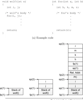
(b) Example of original stack frame before applying stack split
(c) Example of new stack frame after applying stack split
• Before and after a procedure call, the current stack frame is modified to support arguments
passing and code addresses saving for the procedure call.
Since this study focuses on a method for splitting a conventional stack frame, operating systems issues are not considered. For example, it is obvious that sp and fp are saved and restored, respectively, when a current running task is switched out.
Figure 3.1b depicts an example snapshot of stack memory between two functions – wolf() and foo(). This example is simplified for explanation, but it is still based on the GNU ARM cross compiler [28]. The left-most diagram in the figure shows the stack before jumping to the callee function foo(). The next shows the stack after arguments of the callee function foo() are pushed into the stack frame. The right-most is obtained after storing activation records of the callee function foo(), and allocating local variables of the callee function. The numbers in the parentheses offp andsp are time stamps to distinguish different versions of the register values.
3.2.2 New Stack Frame Model by Stack Split
To split the traditional stack frame, extra stack frame pointers are employed. Those registers are called as sub stack frame pointers orsub frame pointers simply and denoted by fp0. Each sub frame pointer indicates a different stack frame from an original stack frame of a procedure. The stack frames located in new memory units are calledsub stack frames orsub frames simply. Therefore, the number of sub frame pointers is same as the number of sub stack frames. For example, if a procedure’s stack frame is split onto three different memory units, the procedure has two sub frame pointers, fp01 and fp02 as well as its original frame pointer fp.
Notice that no extra stack pointers are required. This is because the proposed scheme is a static method so that the size of the sub stack frames is already known when the original frame is split. Then, the new stack frame model can be described as below:
• Either stack pointer (sp) or frame pointer (fp) are employed to provide reference addresses
when accessing an original stack.
• Multiple sub stack frame pointers (fp0) are employed to give reference addresses when
accessing sub stack frames.
• sp indicates the top of the current stack.
• fp indicates the base address of the stack frame of a procedure in the stack.
• Each fp0indicates the base address of each sub stack frame of a procedure.
• At the prologue and epilogue of a procedure, sp, fp, and fp0 are adjusted for allocating
• Before and after a procedure call, the current original stack frame is modified to support
argument passing and code addresses saving for the procedure call.
To summarize this model, the sub stack frames keep part of an original stack frame, and they are responsible only for keeping the automatic variables of a procedure allocated to them. Other functionalities of the stack frame still remain at the original stack frame.
3.3
Stack Frame Splitting Schemes
Moving some parts of a procedure stack frame is a challenging task since it is not supported by current compilers. Moreover, DARTS assigns multiple automatic variables of different exclusive tasks to the shared SPM space. Hence the overlaying of data in SPM must be supported. Two assembly rewriting schemes –default split anddense split – are suggested to improve efficiency of memory utilization by procedure stacks. The difference between the schemes is the memory layout of the original stack frame after applying stack split.
3.3.1 Default Split and Dense Split
The stack split technique modifies assembly code. We modify load or store operations which reference an original stack frame pointer with a data variable’s original offsets to new assembly code which references sub stack frame pointers with new offsets instead. At prologue of the procedure, sub stack frame pointers are adjusted to point at starting points of the procedure’s sub stack frames in different memory units. At epilogue of the procedure, the adjusted sub stack frame pointers’ values are rolled back to their prior values. This is the same as how traditional stack frame pointers are managed. Runtime overhead to adjust the sub stack frame pointers at the prologue and the epilogue is not huge since only several assembly codes lines are newly inserted. Only two lines are enough per procedure in our implementation. If required, other types of instructions which refer to the original stack frame pointer are modified so that they also can access the sub stack frames correctly.
With dense split, the unused space in the original stack frame is removed to save memory space. Each automatic data variable occupies its space in exactly one memory unit over all system memory units. There is no extra space unused by the variable in its original stack frame or in its sub stack frames. This implies that the original stack frame must be modified to remove the unused space, which was used by the data variable but is not used now. Therefore, offsets of all automatic variables of the same procedure must be replaced with new stack frame offsets. For this, all assembly code which references the original stack frame must be examined and modified if necessary. The process also requires changing the prologue and epilogue of a procedure to adjust the original stack size to the new one. This scheme can optimize memory usage and improve performance by using faster memory most efficiently (densely), but it is more risky since more instructions are examined and modified compared to thedefault split.
Figure 3.1c shows a new stack frame after applying those schemes for the same example given above. In this example, variable k and m are allocated into SPM and SDRAM, and they are referenced by fp0p and fp0 d, respectively. When applying the default split technique,
the variables k and m have duplicated memory space over the system memory units. Other variables still stay in the original frame stack without any modification. If the dense split technique is applied, the unused spaces for the variablek and m in the original stack frame are deallocated for saving memory space. For this, the code in the prologue of the function foo() needs to be modified to reduce the amount of allocation for the local variables in the original stack frame. As the original stack frame changes, all other offsets inside of the original frame also need to be recalculated. The offset for the variable h does not need to be recalculated. But the offset for the variable r must be recalculated so that it can be newly assigned to the space for the variablek.
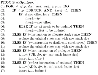
Figure 3.2 presents a pseudo code for the dense split technique targeting the ARM archi-tecture. The notation i(op, dest, src1, src2) means an instruction operating op with register src1 and src2 (optionally) into destination register dest. This scheme supports allocation of the finest granularity level of data and explicitly referenced stack data variables since it handles a stack frame offset of a data object directly. Consequently, it also supports splitting coarser granularity levels such as procedure level and task level (e.g. stack frame, or entire stack). For the default split scheme, the lines to handle data variables remaining in the original stack frame (line 6 – 7) and the lines to manage allocation and deallocation of original stack frame (line 8 – 9, line 10 – 11) can be skipped.
3.3.2 Concerns in Real World Application
![Figure 1.1: Static RAM cell consisting of six transistors [81]](https://thumb-us.123doks.com/thumbv2/123dok_us/1568752.1192841/12.612.191.438.67.291/figure-static-ram-cell-consisting-transistors.webp)