`
Analysis & Simulation of Four Switch BLDC Motor Drive
Three Phase Inverter Control
Swati Joshi1, B.S. Gujar2, Sarika Satpute3
[email protected], [email protected], [email protected]
Abstract-This paper describes the analysis and design of a low cost three phase inverter brushless dc motor (BLDC) drive.For effective utilization of the developed system, a novel direct current controlled pwm scheme (DPC)is designed and implemented.. The operational principle of the four-switch BLDC motor drive and the developed control scheme are theoretically analyzed and the performance is demonstrated by simulation. The main objective of this paper is to describe a low cost four-switch brushless dc (BLDC) motor drive for commercial applications. Speed control of three phase BLDC motor using four switch inverter is proposed to simplify the structure of the conventional six switch inverter. For effective utilization of the developed system, a novel direct current controlled PWM Scheme is designed and implemented to produce the desired dynamic and static speed–torque characteristics. PI controller is used by the outer loop to develop the performance of speed control.
Keywords—Brushless DC (BLDC) motor drive, four-switch inverter.
1. INTRODUCTION.
Permanent-magnet Brushless DC(PMBLDC) motors with trapezoidal back emf finds a variety of applications in aerospace, automotives, industries, military, computers, household products etc. due to higher efficiency, higher torque, higher power factor, increased power density, ease of construction ,ease of control and ease of maintenance. The torque developed by a BLDC motor is constant. A conventional Brushless DC motor is excited by a six switch three phase inverter (SSTPI) where commutation is achieved through an inverter and a position sensor placed 120° apart on the stator. Researchers are always conscious about their cost and are always exploring methods to bring in cost minimization. In this paper cost effectiveness is achieved by reducing the number of power switches, switching driver circuits, dc power supplies, total price and losses. Theoretical analysis and simulations on MATLAB/SIMULINK were conducted to demonstrate the feasibility of the proposed method.
Figure 1. Conventional six-switch three phase BLDC motor drive.
2. ANALYSIS OF A FSTPI-BLDC MOTOR
DRIVE.
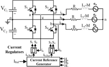
The configuration of a four-switch three phase inverter (FSTPI) BLDC motor is shown in fig 2. The equivalent circuit of the four switch inverter Brushless DC motor drive is shown in figure 3.
Figure 2. Proposed four switch three phase BLDC motor drive.
Figure 3. Equivalent circuit of FSTPI BLDC motor drive.
The equation of a typical BLDC motor is represented as follows:
`
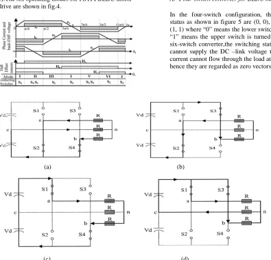
Where Vxn, R, ia, ea, Ls and M represents the phase voltages, resistances, phase currents,self inductances and mutual inductances of phase x,respectively(x=a, b, c).The six operating modes for FSTPI BLDC motor drive are shown in fig.4.
Figure 4. Phase current and trapezoidal back emf of BLDC motor with hall sensor signals.
A. Four-switch converter for BLDC motor drives.
In the four-switch configuration, the four switching status as shown in figure 5 are (0, 0), (0, 1), (1, 0), and (1, 1) where “0” means the lower switch is turned on and “1” means the upper switch is turned on.In the case of six-switch converter,the switching status (0,0) and (1,1) cannot supply the DC –link voltage to the load.So the current cannot flow through the load at these instants and hence they are regarded as zero vectors.
(a) (b)
(c) (d)
Figure 5. Voltage vectors of four switch converter with resistive load: (a)(0,0) vector, (b)(0,1) vector, (c)(1,0) vector, (d)(1,1) vector
However, one phase of the motor is always connected to the midpoint of the dc-link capacitors in the four-switch converter, and hence current flows even at the zero-vector. Moreover, the phase which is connected to the midpoint of dc-link capacitors is uncontrolled and only the resultant current of the other two phases flow through this phase during the switching status (0, 1) and (1, 0).
For a BLDC motor to generate maximum and constant output torque, their phase currents should be rectangular with 120° conducting and 60° non-conducting intervals. Also at each operating mode, only two phases are conducting and the other phase remains silent. However, in the four-switch converter based on the four switching vectors,the generation of 120° conducting and a 60° non-conducting current profiles is inherently difficult. That means the conventional PWM schemes employed for four switch induction motor drives cannot be directly
applied to BLDC motor drives. This led to the development of a new control scheme called Direct Current Controlled PWM scheme.
B. Direct current controlled PWM scheme.
Under a balanced condition, the three-phase currents will satisfy the following condition:
Ia + Ib + Ic=0 (2) This can also be written as Ic=- (Ia + Ib) (3)
In an ac induction motor drive, at any instant there are always three phase currents flowing as:
Ia 0; Ib 0; Ic 0 (4)
`
switches using the hysteresis current control method during each operating mode. Hence this scheme is called the Direct Current Controlled PWM scheme.
C. Current regulation.
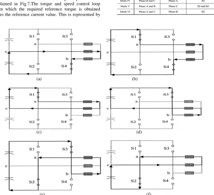
Current is regulated to obtain the required quasi-square waveform. Based on the switching sequences shown in table 1, the current regulation is brought out by hysteresis current control scheme. The switching sequence and corresponding current flow during the six operating modes are depicted in Fig.6. The current regulation and detailed switching sequences are explained in Fig.7.The torque and speed control loop from which the required reference torque is obtained gives the reference current value. This is represented by
the bold line. A smaller band causes higher switching frequency and lower toque ripple. Therefore, the upper and lower bands for hysteresis control are fixed based on these values.
Table-1 Switching sequences of four switch converter
(a) (b)
(c) (d)
(e) (f)
`
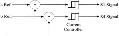
Figure 7. Switching sequence for current regulation
Considering phase A, we can take two cases as follows: Case 1 : Ia>0
Ist Interval : Ia< Lower Limit (LL); S1 is ON IInd Interval : Ia> Upper Limit (UL); S1 is OFF IIIrd Interval : LL<Ia<UL and d/dt (Ia)>0;S1 is ON IVth Interval : LL<Ia<UL and d/dt (Ia)<0;S1 is OFF
Case 2 : Ia<0
Ist Interval : Ia >UL; S2 is ON IInd Interval : Ia< (LL); S2 is OFF
IIIrd Interval : LL<Ia<UL and d/dt (Ia) <0;S2 is ON IVth Interval : LL<Ia<UL and d/dt (Ia) >0;S2 is OFF
The same explanation can be given to phases B and C.
(a) (b)
Figure 8 .Simplified circuits showing modes II and V.(a)Ideal case. (b) Effect of back emf of phase C.
D. Back EMF compensation.
While examining modes II and V, it’s seen that the active phases are phases A and B and the silent phase is phase C. That means, it’s expected that the current through phase C is zero. But the back emf of phase causes an unexpected current to flow through phase C thereby distorting the actual currents in phases A and B. Therefore, while considering the direct current controlled PWM scheme, the back emf compensation problem should also be considered. Fig.8 illustrates the back emf compensation. In Fig.8 (a), the current through phases A and B are same. Therefore any one current need to be sensed, either the current through phase A or that through phase B. If the current through phase A is sensed, then, the switching signal of S1 is determined independently and that of S4 depends on the S1 signal. So phase A current can be regarded as a constant current source. In this case, the current through phase B will be distorted due to the back emf of phase C. Same is the case when phase B is controlled. Here, the current through phase A would be distorted by the back emf of phase C. From this it’s deduced that the currents through phases A and B should be sensed and controlled independently as shown in Fig.9.This is called Direct Phase Current control scheme (DPC).
Figure 9. PWM strategy for Back EMF compensation.
3. SIMULATION RESULTS.
The implementation of four switch brushless dc motor drive system in simulink is shown in Fig.10. The rated BLDC motor parameters are listed in table 2.
Figure 10. Simulink model of FSTPI-BLDC motor
`
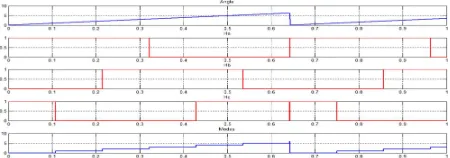
Fig.12.Fig.13 shows the estimated operation modes and Hall Sensor signals Ha,Hb and Hc.
Table-2 Motor Specifications
Figure 11. Back emf waveforms of the three phases.
Figure 12. . Rectangular phase current waveforms of phases A,B and C.
Figure 13. Virtual Hall sensor signals and operating modes.
4. CONCLUSION
A four-switch converter topology is introduced in this paper where cost saving is achieved by reducing the number of inverter power switches. Simulation validates the proposed method. The main advantages of the proposed method are:
• Simplification of power conversion circuit.
• Using four switch inverter, all the six commutation instants can be detected.
• This method can be applied to permanent magnet synchronous motors as it is independent of back emf waveforms.
Therefore, the implementation of the proposed method is easier and less expensive.
REFERENCES
[1] P. Pillay and R. Krishnan, “Modeling, simulation, and analysis of permanent-magnet motor drives. II.The brushless DC motor drive,” IEEE Trans. Ind.Appl., vol. 25, no. 2, pp. 274–279, Mar./Apr. 1989.
[2] B. K. Lee, T. H. Kim, and M. Ehsani, “On the feasibility of four-switch three-phase BLDC motor drives for low cost commercial applications:Topology and control,” IEEE Trans. Power Electron., vol. 18, no. 1, pp.164–172, Jan. 2003.
[3] A. Halvaei Niasar, A. Vahedi,”Modeling, Simulation and implementation of four- switch, brushless dc motor drive based on switching functions.
[4] A.H Niasar, Abolfazl Vahedi, and Hassan Moghbelli, “A novel position sensorless control of a four switch Brushless DC motor drive without phase shifter,” IEEE Trans. Power Electron., vol. 23, no. 6, pp.3079– 3087, Nov. 2008.
[5] P Pillay and R Krishnan,”Modeling, Simulation, and Analysis of Permanent-Magnet Motor Drives ,Part I: The Permanent-Magnet Synchronous Motor Drive,” IEEE Trans. Ind. Appl., vol. 25, no. 2, pp. 265–272, Mar./Apr. 1989.
[6] R. G.Shriwastava M.B.Diagavane S.R.Vaishnav3 “Literature Review of Permanent Magnet AC Motors Drive for Automotive Application”, Buletin TEI March 2012, Vol.1 No.1 pp. 7-14 ISSN: 2089-3191. [7] Purna Chandra Rao , Y. P. Obulesh2 and Ch. Sai Babu
“Mathematical Modeling Of Bldc Motor with closed loop Speed Contol Using pid Controller under Various Loading Conditions”ARPN Journal of Engineering and Applied Sciences O- 2012 volume 7, No. 10 ISSN 1819-6608 PP. 1321-1328.
[8] Jibin M Varghese, Jaya B and Justin Baby “PI tuning control of Four Switch Three Phase Brushless DC Motor” Jan.2008 IEEE transaction Power Electron, volume 23, no1, pp 438-444.
[9] J.Karthikeyan Dr.R.Dhanasekaran “Simulation and Implementation of current control of Brushless [10] Motor based on a common dc signal” International
Journal of Engineering Science and Technology S-2010 Vol. 2(6), 1632-1639.
[11] M.Vignesh Kumar “Speed controls of three phase BLDC Motor using Four Switch Inverter” May-2013 International Journal of Scientific & Engineering Research ISSN 2229-5518 Volume 4, Issue 5 pp. 351- 356.
[12] V.Krishnakumar Dr.S.Jeevanandhan “Four Switch Three Phase Inverter Control of BLDC Motor” International Conference on Electrical Energy Systems 2011 pp. 139-144
[13] Dr.R.Seyezhai “A Comparative Study of Asymmetric and Symmetric Cascaded Multilevel Inverter employing Variable Frequency Carrier based PWM” International Journal of Emerging Technology and Advanced Engineering March 2012 Volume 2, Issue 3, pp. 230- 237
[14] Y. Liu, Z.Q. Zhu, D. Howe “Commutation Torque Ripple Minimization in Direct Torque Controlled PM
`