c e-ISSN: 2348-6848, p- ISSN: 2348-795X Volume 3, Issue 05, March 2016
International Journal of Research (IJR)
Available at http://internationaljournalofresearch.org“Gesture Actuated Robotic Arm’’
[1] Akshay Pisalkar; [2] Nirbhay Khadse ; [3]Pranay Awathare; [4]Divya
Varma & [5] Dhanashree Pimpalkar
Department Of Electronics& Telecommunication Engineering Datta Meghe Institute Of
Engineering, Technology & Research ,Salod,Wardha
[email protected]
[email protected] [email protected]@gmail.com
ABSTRACT
The idea is to change the perception of remote
control for actuating manually operated
Robotic arm. This project presents a thought
and a way to eradicate the bottons, joysticks
and replace them with some other more
intuitive techniques, that is, controlling the
complete Robotic Arm by the operators hand
moment or motion or gesture.In this project the
completely electronics (without mechanical
sensor) way of achiving the above stated goal
is discussed. This is achieved by using
MEMS-ACCELEROMETER and FLEX SENSOR
technology(that is used in smart phones for tilt
sensing), showing the diversity of the
application of the same technology. It is
basically an Accelerometer based system which
controls a robotic arms wirelessly using a
small
and
low-cost,
3-axis
(DOF’s)
accelerometer using Zigbee module. The
accelerometer are mounted on the operator’s
hand and according to the gestures postures of
the operator hand the motors are provided with
the appropriate voltage. This voltage is
pre-tested and depending upon the voltage the
INTRODUCTION
c e-ISSN: 2348-6848, p- ISSN: 2348-795X Volume 3, Issue 05, March 2016
International Journal of Research (IJR)
Available at http://internationaljournalofresearch.orgBLOCK DIAGRAM
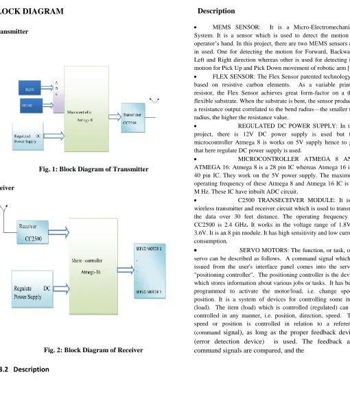
Transmitter
Fig. 1: Block Diagram of Transmitter
Receiver
Fig. 2: Block Diagram of Receiver
3.2 Description
Description
MEMS SENSOR: It is a Micro-Electromechanical
System. It is a sensor which is used to detect the motion of operator’s hand. In this project, there are two MEMS sensors are in used. One for detecting the motion for Forward, Backward, Left and Right direction whereas other is used for detecting the motion for Pick Up and Pick Down movement of robotic arm [1].
FLEX SENSOR: The Flex Sensor patented technology is
based on resistive carbon elements. As a variable printed resistor, the Flex Sensor achieves great form-factor on a thin flexible substrate. When the substrate is bent, the sensor produces a resistance output correlated to the bend radius—the smaller the radius, the higher the resistance value.
REGULATED DC POWER SUPPLY: In this
project, there is 12V DC power supply is used but the microcontroller Atmega 8 is works on 5V supply hence to get that here regulate DC power supply is used.
MICROCONTROLLER ATMEGA 8 AND
ATMEGA 16: Atmega 8 is a 28 pin IC whereas Atmega 16 is a 40 pin IC. They work on the 5V power supply. The maximum operating frequency of these Atmega 8 and Atmega 16 IC is 16 M Hz. These IC have inbuilt ADC circuit.
C2500 TRANSECEIVER MODULE: It is a
wireless transmitter and receiver circuit which is used to transmit the data over 30 feet distance. The operating frequency of
CC2500 is 2.4 GHz. It works in the voltage range of 1.8V –
3.6V. It is an 8 pin module. It has high sensitivity and low current consumption.
SERVO MOTORS: The function, or task, of a
servo can be described as follows. A command signal which is issued from the user's interface panel comes into the servo's "positioning controller". The positioning controller is the device which stores information about various jobs or tasks. It has been programmed to activate the motor/load, i.e. change speed/ position. It is a system of devices for controlling some item (load). The item (load) which is controlled (regulated) can be controlled in any manner, i.e. position, direction, speed. The speed or position is controlled in relation to a reference
(command signal), as long as the proper feedback device
c e-ISSN: 2348-6848, p- ISSN: 2348-795X Volume 3, Issue 05, March 2016
International Journal of Research (IJR)
Available at http://internationaljournalofresearch.orgcorrections made. Thus, the definition of a servo
system is, that it consists of several devices which
control or regulate speed/ position of a load[3].
CIRCUIT DIAGRAM
Transmitter
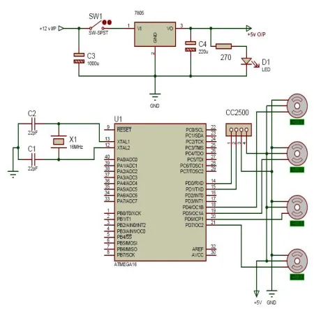
Fig 3: Circuit Diagram of Transmitter
Description:
This is the circuit diagram of transmitter. In this circuit we
use the Atmega 8 which is 28 pin IC and it works on the 5V
supply. We have to use MEMS sensor and flex sensor. The
MEMS sensor are connected to the Port C and the
remaining pins of the both MEMS sensor i.e. pin 3 is
connected to the +5V supply and pin 4 is connected to the
ground. The flex sensor containing five pins out of that four
pins are connected to the port C and the remaining one pin
is ground. The next is the CC2500 Module. It is a
transreceiver module. It can transmit as well as receive the
data. It can be work on 2.4 GHz and its range is 30 feet. The
TxD pin of the CC2500 Module is connected to the RxD pin
Receiver
Fig 4: Circuit Diagram of Receiver
Description:
This is the circuit diagram of the receiver. In this circuit we use Atmega 16 which is 40 pin IC. In the receiver side we use Atmega 16 because in the receiver side there are more connection than the transmitter side and we also require more memory space for the programming so that we use the Atmega 16 in the receiver side. We connect four servo motors containing three pins out of that one pin is connected to the port D and remaining two pins are +5V and ground. Here we also use CC2500 Module for transmitting and receiving purpose. Power supply
c e-ISSN: 2348-6848, p- ISSN: 2348-795X Volume 3, Issue 05, March 2016
International Journal of Research (IJR)
Available at http://internationaljournalofresearch.orgWORKING AREA DETAILS
1) Software 1.1 PCB Artist
PCB Artist is just of many PCB layout software tools available to use, but for understanding of one layout tool easily transfer to any PCB design tool. PCB Artist is a free software tool and can be downloaded for free at www.4pcb.com.
1.2 Atmel Studio 6.0
Atmel Studio 6 is the integrated development platform (IDP) for developing and debugging Atmel Arm Cortex-M and Atmel AVR microcontroller (MCU) based applications Atmega Studio 6 IDP gives you a seamless and easy-to-use environment to write , build and debug your applications written in C/C++ or assembly code.
2) Hardware 2.1 CC2500 Module
It is a transreceiver module. It can transmit as well as receive the data. It can be work on 2.4 GHz and its range is 30 feet.
2.2 Atmega 8, 16
The Atmega 8 which is 28 pin IC and it works on the 5V supply & we used it on transmitter side.. Atmega 16 which is 40 pin IC. In the receiver side we use Atmega 16 because it has more memory space in it.
2.3 SENSORS
MEMS sensor is a Micro-Electromechanical System. It is a sensor which is used to detect the motion of operator’s hand. In this project, there are two MEMS sensors are in used. One for detecting the motion for Forward, Backward, Left and Right direction whereas other is used for detecting the motion for pick up and pick down movement of robotic arm.The Flex Sensor patented technology is based on resistive carbon elements. As a variable printed resistor, the Flex Sensor achieves great form-factor on a thin flexible substrate. When the substrate is bent, the sensor produces a resistance output correlated to the bend radius—the smaller the radius, the higher the resistance value.
2.4 Voltage Regulator IC (7805)
It is a voltage regulator integrated circuit. It is a
member
of 78xx series of fixed linear voltage regulator ICs. 7805
provides +5V regulated power supply.
ADVANTAGES
It allows interactivity in real-time with virtual objects
Can be applied in remote rural areas so as to carry out operations.
Can be used in military areas where highly skilled doctors may not be present.
In application like bomb disposal the human life is not at risk.
APPLICATIONS
• Gesture controlled robotic arm can help in the applications like bomb disposal without risking the human life.
• It can work in remote areas.
•
It can also be used in pick and place applications.FUTURE SCENARIO
Research is going on sixth sense technology to control the robotic arm. This, if achieved will be of great help to the physically handicapped.
CONCLUSION
It provides a better way to control a robotic arm using accelerometer which is more intuitive and easy to work, besides offering the possibility to control a robotic arm by other wireless means. Using this system a non experience a controller can easily control robotic arm quickly and in a natural way. Also, many applications which require precise control and work like human beings can be easily implemented using this approach. The application that was mentioned is successfully fulfilled. And it provides more flexible control mechanism.
REFERENCES
c e-ISSN: 2348-6848, p- ISSN: 2348-795X Volume 3, Issue 05, March 2016