THEORETICAL RATIONALE OF HEATING BLOCK FOR TESTING
BENCH OF AEROSPACE CRAFTS THERMAL PROTECTION ELEMENTS
Anna A. Petrova1, a, Sergey V. Reznik1
1Bauman Moscow State Technical University, 2ya Baumanskaya str., Moscow 105005, Russia
Abstract. The theoretical rationale for the structural layout of a testing bench with zirconium dioxide heating elements on the basis of modelling radiative-conductive heat transfer are presented. The numerical simulation of radiative-conductive heat transfer for the two-dimensional scaled model of the testing segment with the finite-element analysis software package Ansys 15.0 are performed. The simulation results showed that for the selected layout of the heaters the temperature non-uniformity along the length of the sample over time will not exceed 3 % even at a temperature of 2000 K.
1 Introduction
The problem of ‘heat barrier’ caused by the aerodynamic heating of long-range ballistic missiles warheads was successfully solved in the mid 1950-s in Russia and other countries [1, 2]. Effective composite ablative thermal protection coatings (TPC) were used for the first time and the theory for their design was created [3-5]. In the late 1960-s first generation reusable spacecraft of Space Shuttle and Buran type were provided with effective carbon-carbon TPC and high porousity oxide ceramics [6, 7]. Thermal protection issues retain their priority in space technology because of the need to increase the high-temperature resistance of the materials, enhance the performance, and reduce operational and maintenance costs. Carbon-ceramic composite materials (CCCM) have great perspectives as TPC elements [8, 9]. Their advantages include high thermal, chemical and radiation stability and relatively small density.
When designing test methodology for manufacturing trial specimens of rocket and spacecraft elements based on porous and gradient heat-resistant CCCM, the performance capabilities of high thermal loading facilities are of the utmost significance.
TPC testing process employs radiative and convective heating facilities of large dimensions and capacity, with complex starting, regulating and cooling systems [10]. Radiative heating facilities are mostly equipped with halogen incadescent lamps enabling the surface temperature of 1500 K. However, this temperature level is already insufficient for the perspective TPC tests.
Tests of perspective TPC materials and elements demand a laboratory-class facility with the heating elements (HE) that will have better thermals flux levels and degree of uniformity than halogen lamps but will not require a complex cooling system. All of the above makes electrical HE made from zirconium dioxide particularly promising; as they can operate in the air environment at 2500 K surface temperatures for a long time. Their weak point may be low electrical conductivity of zirconium dioxide at temperatures below 1200 K. In [11] this problem was solved by using silicon carbide preliminary heaters in the furnace for high refractory materials.
This paper aims to provide the theoretical rationale for the structural layout of a testing facility with zirconium dioxide HE on the basis of modelling radiative-conductive heat transfer in “HE unit – test object – heat insulation”.
To achieve this aim required creating physical and mathematical models of heat transfer in the testing segment of radiative heating facility, performing numerical simulation, selecting HE layout and justifying the choice of heat-insulating materials.
Known approaches to computation based on solving problems of radiation and combined heat transfer [12-14].
2 Numerical simulation
The research focused on the non-steady radiative-conductive heat transfer (RCHT) between the heater, insulation and the test specimen (Fig.1). The materials were assumed to be homogeneous, isotropic and non-deformable, with temperature-dependent properties. The medium filling the enclosed system was assumed to be diathermic. The density of the incident fluxes was determined allowing for the multiple re-radiation. All bodies were assumed to be diffuse grey, thermal contact was assumed to be ideal.
The above physical model was described by the heat conductivity equations (1) and radiative heat transfer equation (2)
aCorresponding author: [email protected]
DOI: 10.1051
/
COwned by the authors, published by EDP Sciences, 201
/
201
0 0
(201 )
epjconf
EPJ Web of Conferences
,
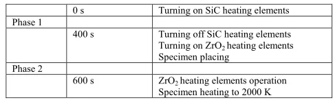
was performed with the finite-element analysis software package Ansys 15.0. The finite-element model employed in the simulation consisted of 53793 nodes and 17528 elements. Due to the specifics described above the simulation process was divided into two stages (Table), lasting correspondingly 400 s and 200 s. In the first phase the zirconium dioxide HE was preheated to 1200 K with silicon carbide HE (Fig. 2). In the second phase the latter were turned off, the specimen was positioned in place and heated to 2000 K at 10 K/s rate. (Fig. 3, 4).
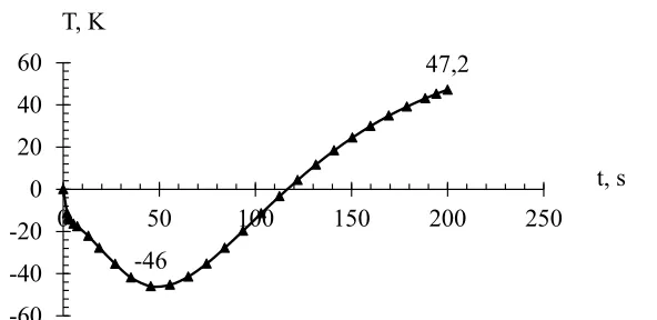
The calculation results presented in Fig. 6 demonstrate that the temperature irregularity at 2000 K did not exceed 47 K, which is equivalent to 3%.
Figure 1. Layout of the radiative heating facility working area: 1– SiC heating element, 2 – high-density ZrO2heating element, 3 – high-density ZrO2heat insulation, 4 – TZMK-10 heat insulation, 5 – specimen.
Table. Heat simulation phases.
0 s Turning on SiC heating elements Phase 1
400 s Turning off SiC heating elements Turning on ZrO2heating elements Specimen placing
Phase 2
Figure 2. Test area temperature field at 400s with 8.5 kW total capacity of 28 heating elements from SiC
Figure 3. Test area temperature field at 600 s with 21 KW total capacity of 27 heating elements from ZrO2
Figure 4. Specimen temperature field at 600 s.
Figure 5. Temperature irregularities of the specimen lengthwise with time.
-46
47,2
-60
-40
-20
0
20
40
60
0
50
100
150
200
250
T, K
Figure 6. Total heat flux values lengthwise.
3 Setup description
The test area of the facility includes HE unit, housing and a sliding part with the sample (Fig. 7). The housing comprises a frame, outer steel-sheet cover, heat insulation, supports and current-conducting wires. The frame is welded from structural steel. The outer cover and supports are joined with bolts. The heating unit consists of 2 rows of heating elements. The first row comprises 28 heat insulated silicon carbide HE, the second row comprises 27 zirconium dioxide HE. The heating elements are powered with current-conducting wires. The wires are fixed to the housing with nuts. Current conducting copper buses are connected to the frame with bolts. To protect operators from electric shock fluoroplastic-4 insulators are provided at the locations of possible contact of current conducting wires with the housing. The minimal distance between separate sources axes is 10 mm. The carriage with the sample can slide along the guides, parallel to the surface of the HE axes. This function is enabled by grooves in the zirconium ceramic insulating walls and an electric motor drive. The heat insulation is made of TZMK-10 material [7], 50 mm thick, and high-porousity ZrO2ceramics [15, 16], 20 mm thick. The inner layer is made up from separate blocks, and the outer
layer is bonded to with adhesive. The testing samples are CCCM plates with 200 mm maximal size and up to 5 mm thickness.
Figure 7. Testing area layout: 1– frame; 2– silicon carbide HE; 3– zirconium dioxide HE; 4– copper buses; 5– fluoroplasic-4 insulators; 6– carriage with the test specimen; 7– specimen; 8– zirconium ceramics heat insulation; 9 – TZMK-10 quartz ceramics heat insulation.
4 Conclusion
The paper presents results of simulating non-steady radiative-conductive heat transfer in the working area of heating test facility. The peculiarities of heating elements justified the choice of the two-step heating mode combinations. The numerical experiment
0,0
0,2
0,4
0
0,05
0,1
0,15
0,2
3% at 10 K/s heating rate. The heating unit is provided with a sliding carriage for the specimen and insulation from heat-resistant ceramic composites.
Acknowledgement
Certain scientific results were obtained within the Agreement for grant № 14.577.21.0099 with Ministry of education and science
of Russian Federation. The unique identifier for applied research (project) RFMEFI57714X0008.
References
1. T.A. Heppenheimer, Facing the Heat Barrier: A History of Hypersonics (Washington, DC, 2007). 2. V. F. Gladkii, Av. and cosm.,2, 13 (2003) [In Russuan]
3. B. M. Pankratov, Yu. V. Polezhaev, A K. Rudko, Vzaimodeistvie materialov s gazovymi potokami (Materials’ interaction with gas flows, M: Mashinostroenie, 1975) [In Russuan]
4. Yu. V. Polezhaev, F. B. Yurevich, Teplovaya zaschita (M: Energiya, 1976) [In Russuan] 5. S. V. Reznik, Materialy i pokrytiya v ekstremalnykh usloviyakh, 1-3, (2002) [In Russuan] 6. V. P. Timoshenko, Aviazionno-kosm. sistemy (M: MAI, 1997) [In Russuan]
7. M. Ya. Gofin, Zharostoikie i teplozaschitnye konstruktsii mnogorazovykh kosmicheskikh apparatov (M.: ZAO “TF “MIR”, 2003)[In Russuan]
8. D. E. Glass, Proceed. 15-th AIAA Space Planes and Hypersonic Systems and Technologies Conference, (2008)[In Russuan] 9. S. V. Reznik, Inzhenernyi zhurnal: nauka i innovatsii,3 (2013) [In Russuan]
10. Yu. V. Polezhaev, S. V. Reznik, eds, Materialy i pokrytiya v ekstremalnykh usloviyakh,3-3, (2002)[In Russuan] 11. D. S. Rutman, A. F. Maurin, G. A. Taksis, Yu. S. Toropov, Ogneupory,8, 53 (1971)[In Russuan]
12. M.F. Modest, Radiative Heat Transfer, 2nd ed., (New York: Academic, 2003)