A Review on 3D Printing and Technologies Used For
Developing 3D Models
Priyanka Takalkar
1, Prof. A. S. Patel
2ME Scholar
1, Asst. Prof.
2, Departme nt of E & TC, MSSCET, Jalna
ABSTRACT
This paper presents the overall study of 3D printing & It’s technologies used to prepare the 3D model. In early
days most of the models are prepare by using material removing techniques instead of the adding material is
known as ‘Subtractive Manufacturing’. The process which adds material in successive patterns to create the desired shape, such method of manufacturing is known as ‘Additive manufacturing’. In AM, 3-D printers are
devices that apply plastic, ceramic and metal, layer by layer, in all three dimensions on a flat surface. 3D printers
can’t print the 3D object without the help of some special algorithms known as G-code. Layer by layer
production allows for much greater flexibility and creativity in the design process. 3D printed products are made
from powder, resin or plastic materials. There are various types of 3D printing technologies such as, Fused
Deposition Modeling (FDM), Stereolithography (SLA), Selective laser sintering (SLS) etc. Nowadays, this technology has been used in jewelry, footwear, industrial design, architecture, engineering, education,
geographic information system and other fields.
Keywords—AM, SM, FDM, SLA, SLS, G-Code.
I.
INTRODUCTION
3D printers are more and more popular all over the world; the workshops will be open in different areas with the rapid development of 3D printing industry [1], So as to save time, manpower and money, ensuring the stability and
the effectiveness of massive 3D printers in wide-area environment. It is a kind of direct manufacturing technology, based on digital model files which can make almost any shape of 3D entities. It is a relatively rising technology
which prints products layer by- layer with material powder or beads [2]. Compared with injection molding and cutting-based on machinery,
3D printing is able to produce custom products at relatively low prices without tools or molds [4].3D Printing uses
software that slices the 3D model into layers (0.01mm thick or less in most cases) [1]. Each layer is then traced onto the build plate by the printer, once the pattern is completed, the build plate is lowered and the next layer is added on top of the previous one. To 3D print an object, a digital model first needs to exist in a computer. This may be fashioned by hand using a computer aided design (CAD) application, or some other variety of 3D modeling software. Alternatively, a digital model may be created by scanning a real object with a 3D scanner, or perhaps by taking a scan of something and then tweaking it with software tools.
In order to be able to print a physical object, i.e. an object in 3 dimensions, a 3D printer needs to be able to move
Figure.1. Model of 3D Printer
Every 3D printer is built around the principle that its 3 principal axes are linear. This means that their axes are at
right angles to each other and that they move in straight lines (that is: they do not rotate). Machines which use this
principle are known as linear robots or Cartesian coordinate robots, as opposed to Delta- or Polar-type robots.
Typical examples of linear robots are 3D printers, but also computer numerical control (CNC) machines. In order
to move along these 3 axes, 3D printers generally make use of fixed rods, timing belts and pulleys, in order to
manoeuvre the print head(s) and or the print platform to the exact position needed. These timing belts and pulleys
are connected to small motors, which are generally referred to as "stepper motors". The stepper motors form an
important part of any printer, as they are in a great part responsible for the quality of your print. The 3-D model is first modeled in a CAD system and STL file is obtained. The STL file is then processed by a slicing procedure resulting in the creation of a tool path. The information produced by the slicing process is saved as computer numerical control (CNC) instructions file which is used by a 3D printer to produce the prototype. G-code is the term used to describe a text file that contains commands to run a CNC machine or 3-D printer [5].
II.
TYPES
OF
3D
PRINTRING
There are many types of 3D printing technologies;
1. FDM-Fused Deposition Modeling:-
Figure.2. Fused Deposition Modeling Technique
2.
SLA-Stereo-lithography:-Stereo-lithography is an additive manufacturing process which employs a vat of liquid ultraviolet curable photopolymer "resin" and an ultraviolet laser to build parts layers one at a time. For each layer, the laser beam traces a cross-section of the part pattern on the surface of the liquid resin. Exposure to the ultraviolet laser light cures and solidifies the pattern traced on the resin and joins it to the layer below.
After the pattern has been traced, the SLA's elevator platform descends by a distance equal to the thickness of a single layer. After being built, parts are immersed in a chemical bath in order to be cleaned of excess resin and are subsequently cured in an ultraviolet oven. Stereo lithography requires the use of supporting structures which serve to attach the part to the elevator platform, prevent deflection due to gravity and hold the cross sections in place so that they resist lateral pressure from the re-coater blade. Supports are generated automatically during the preparation of 3D Computer Aided Design models for use on the stereolithography machine, although they may be manipulated manually. Supports must be removed from the finished product manually, unlike in other, less costly, rapid prototyping technologies.
Figure.3. Stereolithography technique 3. SLS-Selective laser
of the part on the surface of a powder bed. After each cross-section is scanned, the powder bed is lowered by one
layer thickness, a new layer of material is applied on top, and the process is repeated until the part is completed. The SLS machine preheats the bulk powder material in the powder bed somewhat below its melting point, to make it easier for the laser to raise the temperature of the selected regions the rest of the way to the melting point. Compared with other methods of additive manufacturing, SLS can produce parts from a relatively wide range of commercially available powder materials. These include polymers such as nylon (neat, glass-filled, or with other fillers) or polystyrene, metals including steel, titanium, alloy mixtures, and composites and green sand. The physical process can be full melting, partial melting, or liquid-phase sintering. Depending on the material, up to 100% density can be achieved with material properties comparable to those from conventional manufacturing methods.
SLS technology is in wide use around the world due to its ability to easily make very complex geometries directly from digital CAD data. While it began as a way to build prototype parts early in the design cycle, it is increasingly being used in limited-run manufacturing to produce end-use parts.
III.
SOFTWARE
TO
BE
USED
In this paper we describe all the techniques to be used in future work or already used by someone to motivate the 3D printer work step by step. This methods of manufacturing always requires the help of designing algorithms, Which in case uses so may designing algorithms which is executed with the help of simulating software’s like Repetier-Host etc.
This kind of software allows us to import a 3D file in the STL file format, AMF file format; OBJ file format and 3DS file format and view and manipulate it so that it can be printed by the printer very easily. The STL format is the most commonly used format in the 3D printing community. It allows us to import a prepared print job file and preview it virtually as shown in Figure.3. It allows us to communicate with the printer to send the right commands via a USB cable. It provides a user interface to manually control the printer from a computer control. Slicing is the process, in which the software virtually cuts the 3D objects into parts. This is a rather complex trick, so it will take some time. The printer will stack each next slice on top of the previously printed slice.
Figure.3. Appearing Window
IV.
G-CODE
GENERATION
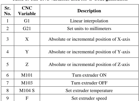
G-code is categorized under the CNC language. G-codes are commands that control the 3-D printer and each G-code has a distinct function. It also has machine (M) codes that control other aspects of the 3-D printer, and the F code that controls the 3-D printers’ extruder speed [6]. The X, Y and Z variables represent the location on the axis. This uses the standard G-code instructions, presented in below in Table.1.
Figure.5. Selective laser sintering technique
Table 1: The CNC variables used for G-Code generation Sr.
No.
CNC
Variable Description
1 G1 Linear interpolation
2 G21 Set units to millimeters
3 X Absolute or incremental position of X-axis
4 Y Absolute or incremental position of Y-axis
5 Z Absolute or incremental position of Z-axis
6 M101 Turn extruder ON
7 M103 Turn extruder OFF
8 M104 S Set extruder temperature
9 F Set extruder speed
Figure.6. (a) Representation of generated G-Code and (b) Sample resultant G-code of the algorithm.
3-D parts have been fabricated or printed using the developed slicing and G-Code generation algorithms. Different settings for the z step size (Z step), also known as the layer height have been used depending on their complexities. Different options for fill settings have been made use of. To avoid warpage on some STL models, options for a raft have been implemented in the code.
V.
ADVANTAGES
The method of layer by layer production allows for much greater flexibility and creativity in the design process.
They can create a part that is lighter and stronger by means of better design. Parts can be completely re-designed so that they are stronger in the areas that they need to be and lighter overall.
Significantly, It speeds up the design and prototyping process. Parts can be created within hours. 3D printing
can brings the design out to a matter of days or weeks compared to months. Also, since the price of 3D printers has decreased over the years, some 3D printers are now within financial reach of the ordinary consumer or small company.
FDM is cheaper method as it uses plastic, more expensive
Models use a different material to remove supports completely. Even cheap 3D printers have enough resolution for many applications.
The Stereo-lithography has high speed model making capacity. Functional parts can be manufactured within a
day. To produce one particular part; It depends on the size and complexity of the project and can last from a few hours to more than a day.
VI.
CONCLUSION
In this paper we have done with the survey of 3D printers and its techniques of manufacturing. We come to know the future of this technology in industrial manufacturing processes. We observe that, some work needs to be done to improve the algorithm. To meet the demand for increasingly more intricate and detailed prototypes, it is necessary to include a computational technique to be used in the generation of support geometry.
the software Repetier-Host to deelop a perfect 3D model within a less time consumption.
REFERENCES
[1] Andrew C. Brown, Deon de Beer “Development of a stereolithography (STL) slicing and G-Code generation algorithm for an entry level 3-D printer” IEEE Transactions.
[2] Massimo Martorellia, Saverio Maietta “Design and Analysis of 3D Customized Models of a Human Mandible” Published by Elsevier in Procedia CIRP 49 (2016) 199 – 202, 2015.
[3] L. M. Galantucci, I. Bodi “Analysis of dimensional performance for a 3D open-source printer based on fused deposition modeling technique” Published by Elsevier in 3rd CIRP Global Web Conference Procedia CIRP
28 ( 2015 ) 82 – 87, 2014.
[4] Jun Yang, Yang Yang “A Personal Desktop Liquid-Metal Printer as a Pervasive Electronics Manufacturing Tool forSociety in the Near Future” Published by Engineering Sciences Press, Volume1, Issue 4, December 2015.
[5] A book by Christopher Barnatt “3D Printing: The Next Industrial Revolution” ISBN: 978-1484181768, 2015. [6] Yoshiki Nakamura, Chihiro Hayashi “Measuring the Effect of 3D Printing Machinery on Technology
Management” Proceeding of PICMET’16, 2016.
[7] W.P. Bula1, Y. Takahata “Hybrid Technology (3d Additive Printing – Silicon – Glass) Multiline Evaporative Concentrator For Water Quality Monitoring System” IEEE Transaction, Barcelona, Spain, 16-20 June 2013. [8] David D. Hernandez “Factors Affecting Dimensional Precision of Consumer 3D Printing” International
Journal of Aviation, Aeronautics, and Aerospace, Volume 2 Issue 4, 2015.
[9] Frederic Gianesello, Aimeric Bisognin “3D Printing Technology: Enabling Innovative & Cost Effective Industrial Antenna Solution”IEEE Transaction, 2016.