University of Windsor University of Windsor
Scholarship at UWindsor
Scholarship at UWindsor
Electronic Theses and Dissertations Theses, Dissertations, and Major Papers
2012
New metrics for space-time decoding with imperfect
New metrics for space-time decoding with imperfect
synchronization
synchronization
GARIMA DEEP University of Windsor
Follow this and additional works at: https://scholar.uwindsor.ca/etd
Recommended Citation Recommended Citation
DEEP, GARIMA, "New metrics for space-time decoding with imperfect synchronization" (2012). Electronic Theses and Dissertations. 120.
https://scholar.uwindsor.ca/etd/120
NEW METRICS FOR SPACE-TIME DECODING
WITH IMPERFECT SYNCHRONIZATION
by
Garima Deep
A Thesis
Submitted to the Faculty of Graduate Studies through Electrical and Computer Engineering
in Partial Fulfillment of the Requirements for the Degree of Master of Applied Science at the
University of Windsor
Windsor, Ontario, Canada
NEW METRICS FOR SPACE-TIME DECODING
WITH IMPERFECT SYNCHRONIZATION
by
Garima Deep
APPROVED BY:
Dr. Robin Gras School of Computer Science
Dr. Majid Ahmadi
Department of Electrical and Computer Engineering
Dr. Behnam Shahrrava
Department of Electrical and Computer Engineering
Dr. Mitra Mirhassani Chair of Defense
Declaration of Previous Publications
This thesis includes 2 original papers that have been previously submitted for publication
in peer reviewed journals and conferences, as follows:
Thesis Chapter Publication title/full citation Publication
status
Chapter 5 G. Deep, B. Shahrrava, S. Sinha “Space-Time
De-coding with Imperfect Synchronization”; IEEE
In-ternational Global Telecommunication Conference
submitted
Chapter 5 G. Deep, B. Shahrrava, S. Sinha “Optimal
Space-Time Decoding with Imperfect Synchronization”;
2012 IEEE Workshop on Signal Processing
Sys-tems
submitted
I certify that I have obtained a written permission from the copyright owner(s) to include
the above published material(s) in my thesis. I certify that the above material describes
work completed during my registration as graduate student at the University of Windsor.
I declare that, to the best of my knowledge, my thesis does not infringe upon anyones
copyright nor violate any proprietary rights and that any ideas, techniques, quotations, or
any other material from the work of other people included in my thesis, published or
Fur-thermore, to the extent that I have included copyrighted material that surpasses the bounds
of fair dealing within the meaning of the Canada Copyright Act, I certify that I have
ob-tained a written permission from the copyright owner(s) to include such material(s) in my
thesis.
I declare that this is a true copy of my thesis, including any final revisions, as approved
by my thesis committee and the Graduate Studies office, and that this thesis has not been
Co-Authorship Declaration
I hereby declare that this thesis incorporates material that is result of joint research, as
follows:
This thesis also incorporates the outcome of a joint research undertaken in
collabora-tion with Shayondip Sinha under the supervision of professor Dr. Behnam Shahrrava. The
collaboration is covered in Chapter 5 of the thesis. In all cases, the key ideas, primary
con-tributions, experimental designs, data analysis and interpretation, were performed by the
author, and the contributions of co-authors were primarily through the provision of proof
reading and reviewing the research papers regarding the technical content.
I am aware of the University of Windsor Senate Policy on Authorship and I certify that
I have properly acknowledged the contribution of other researchers to my thesis, and have
obtained written permission from each of the co-authors to include the above materials in
my thesis.
I certify that, with the above qualification, this thesis, and the research to which it refers,
Abstract
This thesis emphasizes the unexploited challenges in an unsynchronized space-time block
coded (STBC) system. This research involves the unknown Rayleigh fading channel
pa-rameters and the carrier frequency offset (CFO) at the receiver. Plenty of research has been
done on the optimal estimation of these parameters over the period of time. Considering
a practical receiver system with a non-ideal estimator leads to the necessity of introducing
the erroneous estimates of these unknown parameters into the detection algorithm. It is
therefore necessary to augment the existing conventional detectors, such as maximum
like-lihood (ML), maximal ratio combiner (MRC) and minimum mean square error (MMSE).
This work is an extension of these conventional detection schemes, which will make the
proposed detectors capable of overcoming the challenge of mismatch scenario. The
pro-posed detectors are designed to optimize the output at the receiver, for various estimation
error variances of the uncertainties. Extensive simulation results demonstrate that the
pro-posed schemes outperform conventional detectors. The performance of these propro-posed
detectors is analyzed by plotting the bit error rate (BER) over signal to noise ratio (SNR)
curves for various modulation schemes, such as M-PSK and M-QAM. At the end, the
com-putational complexities of the proposed detectors from the implementation point of view is
Acknowledgements
Firstly, I would like to thank my advisor, Dr. Behnam Shahrrava, for his guidance and
constant support throughout my Masters program. He has been an excellent guide who
developed my interest in research and demonstrated concern for every complication I faced
during this research work. His insight on the subject and comments were invaluable and it
was a pleasure to work with him.
I would like to express my gratitude to Dr. Robin Gras and Dr. Majid Ahmadi for
giv-ing me valuable feedback and for their time spent servgiv-ing my graduate committee. I would
also like to express my deep gratitude to Dr. Nihar Biswas for his extended help and
will-ingness to offer advice at each step along the way. My special thanks to the departmental
staffs, particularly, Ms. Andria Ballo, Ms. Shelby Marchand and Mr. Frank Cicchello for
their support and for providing me an excellent work environment.
I feel highly gratified towards my friends Ashirbani Saha, Dibyendu Mukherjee, Dr.
Gaurav Bhatnagar and Shayondip Sinha for all the help they provided, the knowledge they
shared and the resources they made available, without which the research would not have
been this successful.
My motivation is my grandfather who taught me to work hard and reach higher. His
love and affection encouraged me to complete my research early so that I could spend more
and encouragement of my’chachijis,’who never let me feel away from mom and home, my
’chachajis,’who walked those extra miles to make sure I was safe and my cousin brothers, who made me feel like a princess in their empire.
I owe this all to my parents and my brother, who were beside me at every step. Their
daily phone calls to ask my progress in research and to keep me connected with the almighty,
helped me in every aspect, which I will never forget. I feel their dreams are going to come
true and their prayers seem to be answered.
Finally, I would like to thank my ’mamaji,’ for his constant encouragement to attain higher education and make my family feel proud of me.
Above all, the success of my work make me feel, the presence of my late grandma and
her blessings being showered on me.
Table of Contents
Page
Declaration of Previous Publications . . . iii
Co-Authorship Declaration . . . v
Abstract . . . vi
Acknowledgements . . . viii
List of Tables . . . xiv
List of Figures . . . xv
List of Acronyms . . . xvii
Glossary of Symbols . . . xix
1 Introduction . . . 1
1.1 Transmitter Module . . . 2
1.1.1 Modulation Techniques . . . 2
1.1.1.1 M-QAM . . . 3
1.1.1.2 M-PSK . . . 4
1.1.2 Diversity Schemes . . . 5
1.1.2.1 Time Diversity . . . 7
1.1.2.2 Frequency Diversity . . . 7
1.1.2.3 Phase Diversity . . . 7
1.1.2.4 Code Diversity . . . 7
1.1.2.5 Space Diversity . . . 8
1.1.3.1 SISO . . . 8
1.1.3.2 SIMO . . . 8
1.1.3.3 MISO . . . 9
1.1.3.4 MIMO . . . 9
1.2 Channel Module . . . 10
1.2.1 Channel State Information . . . 11
1.2.2 AWGN . . . 11
1.3 Receiver Module . . . 12
1.3.1 Synchronized Receiver . . . 13
1.3.2 Unsynchronized Receiver . . . 14
1.4 Objective of the Research . . . 15
1.5 Structure of the Thesis . . . 16
2 Literature Review . . . 18
3 Space-Time Block Coding . . . 21
3.1 Introduction . . . 21
3.2 STBC System Model . . . 22
3.2.1 STBC Transmitter . . . 23
3.2.2 STBC Receiver . . . 24
3.2.2.1 MRC combiner scheme . . . 25
3.2.2.2 ML decision scheme . . . 26
3.3 Effect of parameter estimation errors . . . 27
3.3.1 System model with unknown CSI . . . 27
3.3.1.1 Simulation performance of unknown CSI . . . 29
3.3.2 System model with unknown CFO . . . 33
3.3.2.1 Simulation performance of unknown CFO . . . 35
4 STBC detection techniques . . . 39
4.1 Maximum Likelihood detector . . . 40
4.1.2 ML detector with unknown CSI based upon CEP . . . 42
4.1.3 ML detector with unknown CSI & CFO based upon CEP . . . 43
4.2 Maximal Ratio Combiner and ML detection scheme . . . 44
4.2.1 MRC System discription . . . 45
4.2.2 MRC detector with unknown CSI based upon CEP . . . 46
4.2.3 MRC detector with unknown CSI & CFO based upon CEP . . . 48
4.3 Minimum Mean Square Error detector . . . 49
4.3.1 MMSE System discription . . . 50
4.3.2 MMSE detector with unknown CSI based upon CEP . . . 52
4.3.3 MMSE detector with unknown CSI & CFO based upon CEP . . . . 53
5 Proposed detection schemes based upon the unknown CSI and CFO estima-tion errors . . . 55
5.1 Overview . . . 55
5.2 Assumptions . . . 57
5.3 Proposed ML detector . . . 58
5.3.1 Convergence to conventional ML detector . . . 60
5.4 Proposed MRC detector . . . 61
5.4.1 ML Detection Methodology . . . 63
5.4.2 Convergence to conventional MRC detector . . . 63
5.5 Proposed MMSE detector . . . 64
5.5.1 Convergence to conventional MMSE detector . . . 66
5.6 Simulation analysis . . . 67
6 Conclusion and Future Work . . . 75
References . . . 77
Appendix A Mathematical Calculations . . . 87
A.1 Conditional PDF of CAFO . . . 87
A.3 Conditional Expectation of Received Signal . . . 90
A.4 Conditional Variance of Received Signal . . . 91
List of Tables
3.1 Data transmission . . . 23
List of Figures
1.1 Generic block diagram of wireless communication system. . . 2
1.2 Signal space diagram of QAM modulations. . . 3
1.3 Signal space diagram of PSK modulations. . . 4
1.4 Diversity Schemes. . . 6
1.5 Types of Space/Antenna Diversity. . . 9
1.6 Multipath fading in wireless communication system. . . 10
1.7 Modulation Block Diagram . . . 12
1.8 Synchronized demodulation . . . 13
1.9 Unsynchronized demodulation . . . 14
3.1 Space Time Coding. . . 21
3.2 Space Time Block Coding transmitter. . . 23
3.3 Space Time Block Coding receiver. . . 24
3.4 Performance of 4-PSK STBC system for different pilot length. . . 30
3.5 Performance of M-PSK STBC system for different pilot length. . . 31
3.6 Performance of M-QAM STBC system for different pilot length. . . 32
3.7 Performance of unsynchronized 4-PSK STBC system under mismatch sce-nario. . . 35
3.9 Performance of unsynchronized 4-QAM STBC system under mismatch
scenario. . . 37
3.10 Performance of unsynchronized M-QAM STBC system under mismatch scenario. . . 38
4.1 An ideal ML detector receiver . . . 40
4.2 An ML detector with unknown CSI estimates . . . 42
4.3 An unsynchronized ML detector with unknown CSI estimates . . . 43
4.4 An ideal MRC detector receiver . . . 45
4.5 An MRC detector with unknown CSI estimates . . . 47
4.6 An unsynchronized MRC detector with unknown CSI estimates . . . 48
4.7 An ideal MMSE detector receiver . . . 49
4.8 Vector diagram of MSE . . . 50
4.9 An MMSE detector with unknown CSI estimates . . . 52
4.10 An unsynchronized MMSE detector with unknown CSI estimates . . . 53
5.1 Performance of 4-PSK STBC system with proposed detector. . . 69
5.2 Performance of 4-PSK STBC system with proposed detector. . . 70
5.3 Performance of M-PSK STBC system with proposed detector. . . 71
5.4 Performance of 4-QAM STBC system with proposed detector. . . 72
List of Acronyms
AWGN Additive White Gaussian Noise
AM Amplitude Modulation
BER Bit Error Rate
BS Base Station
CAFO Carrier Angular Frequency Offset
CEP Certainty Equivalence Principle
CFO Carrier Frequency Offset
CSI Channel State Information
iid Independent and Identically Distributed
ICI Inter Carrier Interference
LTE Long Term Evolution
MA Multiple Antenna
ML Maximum Likelihood
MSE Mean Square Error
MMSE Minimum Mean Square Error
MRC Maximal Ratio Combining
O-PSI Orthogonal Pilot Sequence Insertion
PSK Phase Shift Keying
QAM Quadrature Amplitude Modulation
RU Remote Unit
RV Random Variable
SED Squared Euclidean Distance
SIMO Single Input Multiple Output
SISO Single Input Single Output
SNR Signal-to-Noise Ratio
STBC Space-Time Block Coding
STC Space-Time Codes
STTC Space-Time Trellis Codes
Glossary of Symbols
[.]T Transpose of a vector or matrix
[.]∗ Complex conjugate of a vector or matrix
[.]H Hermitian of a vector or matrix
∥.∥ Euclidean norm
ℜ{.} Real value of a variable
⊥ Orthogonal
ln Natural logarithm
E[.] Expected value of a random variable
V ar[.] Variance of a random variable
P (x) Probability of the occurrence ofx
j √−1
f(.) Probability density function
A∼ N(µ, σ2
Chapter 1
Introduction
Today, Wireless Communication has a significant impact on everyone’s life. The
develop-ment of the endless enabling technologies like advanced mobile phones with digital
cam-eras, wireless internet, television, radios etc. keep us connected and provide us with all
sort of information from all around the world. With the evolution of these rapidly
devel-oping crucial technologies, wireless communication (WC) became an indispensable field
of research. To cope up with increasing demands for simple, highly efficient and unified
technology, the main objective is to have a quality and reliable transmission of the signal.
With the increasing number of end-users, the obstacle ahead is the restriction on limited
bandwidth. Researchers from all around the world are constantly exploring the techniques
for bandwidth extension and spectrum aggregation. Some emerging nations have adopted
the advanced wireless communication 4G Long Term Evolution (LTE) technology, which
promises to cater the ever increasing data rate demand.
To understand the fundamental concept of WC system Fig. 1.1 shows a general block
diagram of a WC system which can be broadly modeled as, implicit transmission of
infor-mation signal propagating on the physical medium called channel and its reconstruction to
Figure 1.1: Generic block diagram of wireless communication system.
1.1
Transmitter Module
The main characteristic of a transmitter is to modify the data bits into an electric signal
referred as baseband signal. The baseband signal is then processed to ease its transmission
through the channel. These signal processing involves amplification, modulation on a high
frequency carrier wave etc. for efficient transmission.
1.1.1
Modulation Techniques
Modulation, the fundamental block of communication is defined as a process which
in-volves varying some parameter of the carrier signal in accordance to the instantaneous
value of the baseband signal for suitable transmission over the channel [1]. In the new
era, digital communication is used for its tremendous advantages over the analog
com-munication. In digital communication, the modulator maps the input binary codeword to
analog carrier signal for transmission. There are many modulation schemes [2, 3] currently
employed on WC system. The work presented in this thesis is on the major modulation
1.1.1.1 M-QAM
Amplitude modulation (AM) is defined as a system in which the amplitude of the
contin-uous carrier wave is varied in accordance to the instantaneous amplitude of the baseband
signal [4]. Thus, the unique property of AM wave is that, its frequency and phase remains
constant however, the varying envelop of the modulated carrier wave contains all the
infor-mation of the baseband signal. Quadrature amplitude modulation (QAM) can be done in
various rates [5] as shown in 1.2. Taking advantage of its remarkable performance [6–8]
in various systems, it has proved to be one of the most popular methods employed for high
technology wireless systems [9, 10].
(a) 4-QAM modulation
(b) 16-QAM modulation (c) 64-QAM modulation
1.1.1.2 M-PSK
In digital communication, when the modulation process involves switching or keying the
phase of the high frequency carrier wave in accordance to the digital baseband signal, this
process is called Phase Shift Keying (PSK). PSK has a constant envelop and varying phase
hence is less prone to external interferences, contrary to AM which is more pronounced to
external noise. The performance of PSK in WC system has been vastly done in [11–14]
for various areas of interest. Figure. 1.3 shows various PSK modulation techniques used in
this research for studying the system performance.
(a) 4-PSK modulation
(b) 8-PSK modulation (c) 16-PSK modulation
Modulation has proved to be of tremendous importance in WC. The quality of
trans-mission lies in higher signal to noise ratio. The lower modulation schemes work well on
lower SNR. However, they have lower data rate. Although, the higher order modulation
schemes require higher SNR for optimal transmission, its unduly advantage is its higher
data rates.
The higher modulation indexes have advantages over the lower as:
• The bandwidth for M-modulation schemes is M times less as compared to the lower modulation schemes for same BER.
• Due to the reduced bandwidth, the bit transmission rate is higher for higher modula-tion schemes
There has been enormous research done for the best modulation scheme [15–18]. It all
depends upon the required data rate, transmission medium and fading in the channel.
1.1.2
Diversity Schemes
In Wireless Communication world, the main objective is to have a quality and reliable
transmission of the signal. However due to adverse weather conditions, variation in time,
geographical regions etc., it is very difficult to have an incorrupt speech or data signal.
As mentioned below, another major challenge of WC system is the uncertain channel
co-efficients. The transmitted signal propagates from a multipath channel, where the signal
fluctuates over a period of time or distance transverse. Multipath propagation gives rise to
inter carrier interference (ICI) and degrades the system performance, which is termed as
’fading’. This thesis emphasizes on multipath fading, which imposes difficulties in
opti-mum reception of the baseband signal.
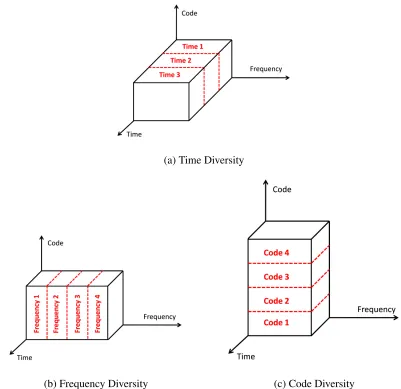
Diversity is a technique to mitigate the effect of fading and ICI [19, 20]. ’Diversity’ in
the receiver over different channels, so that it becomes more probable to detect the original
signal. There are several classes of diversity schemes employed at the transmitter for more
reliable signal reception.
(a) Time Diversity
(b) Frequency Diversity (c) Code Diversity
1.1.2.1 Time Diversity
Time diversity is the most common diversity where redundant data are time interleaved
so that they experience independent fades. An error correcting code added to the signal
simplifies the error and avoids error bursts.
1.1.2.2 Frequency Diversity
In Frequency diversity, redundant data symbols are transmitted over multiple frequency
bands. The different carrier frequencies are selected in such a way so that each individual
data symbol on a carrier experience independent fading.
1.1.2.3 Phase Diversity
The broadband signal is processed in a similar way as the frequency diversity. However, in
phase diversity, the different replicas of the same baseband signal are modulated over the
carrier with different phases. In this diversity scheme, the time and frequency are constant
over the channel. The receiver oscillator is tuned to the different phases of the carrier to
demodulate the baseband signal with less probably to lose the original data due to different
multipath fading.
1.1.2.4 Code Diversity
Code diversity provides improved system performance by encoding the baseband signal
to specific code sequences before modulating it on the carrier. On the receiver side, the
signal is demodulated and the encoded data is decoded into its original form. In this way,
code diversity provides security and higher coding gain without any bandwidth expansion.
The effectiveness of code diversity to combat fading made it evolve remarkably with the
1.1.2.5 Space Diversity
Space diversity is an effective diversity technique [21–23] where multiple transmitters
and/or multiple receiver antennas are employed to transmit the replicas of the baseband
signal. Multiple antennas ensure independent fading across different channels. The
re-ceiver combines the multipath signal to reconstruct the optimal baseband signal. The space
diversity is also known as antenna diversity. There are other diversity schemes like
angu-lar diversity where redundant data is send over directional antennas, poangu-larization diversity
where the advantage of antenna polarization is taken to achieve diversity, etc.
1.1.3
Space Antenna Diversity
Space/Antenna Diversity can be categorized as:
1.1.3.1 SISO
Single-input single-output antenna is a basic communication model with one transmitter
and one receiver. SISO does not employ antenna diversity technique. Today, SISO models
are used to compare the performance of antenna diversity schemes over the basic WC
system.
1.1.3.2 SIMO
Single-input multiple-output antenna diversity holds for a system with single transmitter
and multiple receivers. SIMO is the most primitive technique also termed as receiver
di-versity [24, 25]. In SIMO, receiver effectively combines the multiple copies of the same
transmitted signal over multiple channels to maximize the SNR of the output signal.
Con-sideration the demand is of a simple, highly efficient, pocket remote unit (RU), SIMO
tech-nique is applied in the uplink of a WC system with single antenna at the RU and multiple
T R A N S M I T T E R R E C E I V E R
(a) Single Input Single Output
T R A N S M I T T E R R E C E I V E R
(b) Single Input Multiple Output
T R A N S M I T T E R R E C E I V E R
(c) Multiple Input Single Output
T R A N S M I T T E R R E C E I V E R
(d) Multiple Input Multiple Output
Figure 1.5: Types of Space/Antenna Diversity.
1.1.3.3 MISO
Multiple-input single-output antenna diversity employs multiple antennas at the transmitter
and single antenna at the receiver. MISO diversity has been exploited recently and is also
termed as transmitter diversity [29–31]. This scheme is employed in the downlink of a WC
system, with single antenna at receiver to keep it light and less complex.
1.1.3.4 MIMO
Multiple input multiple output (MIMO) system exploits the advantage of having
antenna technology. While MIMO systems account more complexity at both transmitter
and receiver, however, its proficient signal processing algorithms provide better quality of
transmission and support superior data transfer rates [34–36] as compared to the traditional
SISO antenna system.
1.2
Channel Module
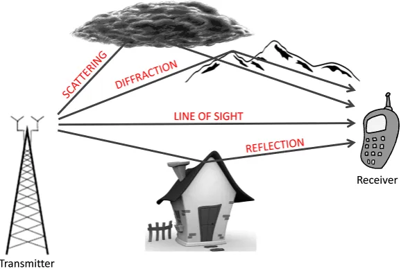
Figure 1.6: Multipath fading in wireless communication system.
As shown in the block diagram in Fig. 1.1, channel is a medium through which the
electrical signals propagate from transmitter to the receiver. In real sense, channel is a filter
which attenuates and deteriorates the transmitted signal. Fig. 1.6 demonstrates how a signal
propagate after scattering, reflecting, refracting, deflecting in a practical scenario. The
re-ceived signal is not a mere line of sight, but copies of multipath transmissions encountered
from different directions, time and energy. Thus the unpredictable channel makes the WC
1.2.1
Channel State Information
The channel plays an important role in designing communication system. There are various
types of fading channels and a survey of their error performance is done in [37]. In this
thesis, we will examine the impact of Rayleigh fading in the mobile radio channel on the
transmitted signal [38].
As given in [39], the received signal rapidly fluctuates in space, time or frequency
do-main and scatters due to the interfering objects in between the transmitter and the receiver.
Rayleigh Fading applies to the case when no dominant signal propagated along the line
of sight. Thus, the received signal is a superposition of all the scattered faded signals.
Hence, by central limit theorem [40], Rayleigh channel is characterized as a random
vari-able who’s real and imaginary parts are zero mean independent and identically distributed
(IID) Gaussian variables with equal variance.
hi =αie(jθα) (1.1)
Whereαi is the amplitude of the ith sinusoid which is a constant of 1 in our case,θαis
the random phase uniformly distributed from zero to 2π . Therefore, the envelope of the
received signal follows a Rayleigh distribution with following pdf:
fH(h) = h σ2 e
( −h2
2σ2 )
(1.2)
where σ2 is the variance of the channel coefficient. Channel fading is also caused by
motion of the receiver. This movement introduces Doppler Shift in the received signal,
which is the relative change in the frequency of the propagating signal due to the motion of
the receiver.
1.2.2
AWGN
Noise is another important factor that has tremendous impact on the signal. Noise is an
unwanted, unpredictable, random interference which distorts the signal and cannot be
over a channel. SNR is a measurement which is defined as signal power to the noise power.
Thus, lower noise maintains higher SNR, enabling successful data transmission over the
wireless channel. Whereas, higher noise demolishes SNR and distorts the signal to an
extent, that cannot be recovered accurately at the receiver.
In addition to the multiplicative channel coefficient, this noise is considered an additive
counterpart of the final received signal in every wireless communication system. The noise
is considered a random variable with Gaussian distribution and a flat power spectral density
over the bandwidth of the signal. Thus, it is categorized as additive white Gaussian noise
(AWGN).
1.3
Receiver Module
As explained above, the transmitter’s primary purpose is to deliver the message signal to
the receiver. For an accurate transmission of the information signal, transmitter modulates
the baseband signal to make it suitable for transmitting over the channel. Similarly, the
receiver demodulates the received signal to recreate the baseband signal. Thus, the receiver
circuit is most important for an optimal detection of the signal. The following section
demonstrates the mathematical calculations for the demodulation of the two receivers with
synchronized carrier oscillator and unsynchronized oscillator.
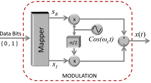
Block diagram in Fig. 1.7 demonstrates how a complex baseband signal is modulated
over the high frequency carrier wave. Depending on different modulation schemes, the
complex baseband signal is mapped to a form s = sR + jsI. The baseband signal is
then modulated with a carrier wave of frequencyfc. Thus the radio frequency (RF) signal
transmitted from the antenna can be given by
x(t) = ℜ{se(jωct)}
=ℜ {(sR+jsI) (cos (ωct) +jsin (ωct))}
=sRcos (ωct)−sIsin (ωct),
(1.3)
whereωc= 2πfc.
1.3.1
Synchronized Receiver
Figure 1.8: Generic block diagram of synchronized demodulation in wireless
communica-tion system.
In ideal scenario, the oscillator of the receiver should be in synchronization with the
same carrier frequencyfcas that of the transmitter, as shown in Fig. 1.8. The RF signal at
the receiver is of the form
The demodulation of the received signal at branch one becomes,
2r(t) cos (ωct) = 2rRcos2(ωct)−2rIsin (ωct) cos (ωct)
=rR{cos (2ωct) + 1} −rI{sin (2ωct)}.
(1.5)
It is then passed through a low pass filter and the output isrR. Similarly, in branch two
−2r(t) sin (ωct) = −2rRcos (ωct) sin (ωct) + 2rIsin2(ωct)
=−rR{sin (2ωct)}+rI{1−cos (2ωct)}.
(1.6)
This is also passed through a low pass filter with an outputrI. The signal is further sampled
to obtain the digital baseband signal.
1.3.2
Unsynchronized Receiver
Figure 1.9: Generic block diagram of unsynchronized demodulation in wireless
communi-cation system.
As discussed above, in order to perfectly retrieve the baseband signal, the oscillator
fre-quency of the receiver should be ideally tuned to the carrier frefre-quency. However in practical
scenario, the two frequencies differ. This happens due to varied reasons like Doppler shifts
or device impairment causing physical differences between the local oscillators of
CFO introduces ICI by destroying the orthogonality between the carriers and thus causes
acute reduction in SNR. Thus, CFO has to be estimated at the receiver because it
deterio-rates the performance of the system during demodulation, which can be expressed in the
form
△ω =ωc−ωr
⇒2π△f = 2πfc−2πfr,
(1.7)
where△f is the CFO which is a difference betweenfc, the carrier frequency and fr, the frequency of the receiver oscillator. The demodulation of the received signal at branch one
becomes,
2r(t) cos (ωrt) = 2rR [
cos2(ωct) cos (∆ωt) + cos (ωct) sin (ωct) sin (∆ωt) ]
−2rI [
sin (ωct) cos (ωct) cos (∆ωt) + sin2(ωct) sin (∆ωt) ]
=rR[{1 + cos (2ωct)}cos (∆ωt) + sin (2ωct) sin (∆ωt)]
−rI[sin (2ωct) cos (∆ωt) +{1−cos (2ωct)}sin (∆ωt)].
(1.8)
It is then passed through a low pass filter and the in-phase output rin is rRcos (∆ωt)−
rIsin (∆ωt). Similarly, in branch two
−2r(t) sin (ωrt) =− 2rR [
cos (ωct) sin (ωct) cos (∆ωt)−cos2(ωct) sin (∆ωt) ]
2rI [
sin2(ωct) cos (∆ωt)−sin (ωct) cos (ωct) sin (∆ωt) ]
=− rR[sin (2ωct) cos (∆ωt)− {1 + cos (2ωct) sin (∆ωt)}]
+rI[{1−cos (2ωct)}cos (∆ωt)−sin (2ωct) sin (∆ωt)].
(1.9)
This is also passed through a low pass filter with the quadrature-phase output rquad as
rRsin (∆ωt) +rIcos (∆ωt). The signal thus contain a carrier frequency offset term, which
does not allow an optimal detection of the baseband signal and has to be removed.
1.4
Objective of the Research
An optimum reception of the baseband signal is of great importance for mainly two
copies of the transmitted signal through multiple unknown channels with different powers
and degradations. Ideal detection algorithms are designed with an assumption that the CSI
is perfectly known to the receiver. However, practical systems require estimating the
chan-nel fading parameters before detection of the baseband signal. Besides unknown chanchan-nel
parameters, in a MA system, the propagation of baseband signal through multipaths can
undergo co-channel interference or even loss of data due to Doppler shift. Doppler shift
or even oscillators impairments can introduce CFO which is unavoidable in an
unsynchro-nized system.
This research examines all the problems discussed above and focuses on designing
detectors at the receivers. The aim is to achieve optimal detection of the multiple
trans-missions of the message signal through a flat Rayleigh fading environment and addition
of AWGN noise. To supersede the effect of interference, space-time block coding (STBC)
scheme (discussed in Chapter 3) is used to maintain orthogonality between the baseband
signals transmitted over multiple antennas. The detectors are modeled under combined
impairments of imperfect CSI and CFO. The algorithms are designed for three prevalent
detection techniques, incorporating the estimation error variances associated with the
es-timates of channel fading parameters and CFO. Simulations are performed and analyzed
in terms of BER for various proposed detectors, which outperform in comparison to the
conventional detection techniques.
1.5
Structure of the Thesis
The rest of the thesis is organized as follows.
Chapter 2 presents a Literature Review, giving an overview and timeline of the research
subject and different approaches taken in the past. It also explains how this research is a
step ahead and makes it of great importance in a WC system.
Chapter 3 starts with an overview of space-time codes (STC) techniques. Then a
emphasis on the two-transmit one receive diversity STBC scheme. This scheme is further
presented with their performance analysis under unknown CSI and imperfect estimates
of these channel coefficients, as proposed by Tarokh. Discussing the impairments due to
CFO, this STBC system model is further extended incorporating the error variances of the
erroneous estimates of CFO into the system.
Chapter 4 a detailed review of the three of the most prevalent detection techniques
is introduced with their performance analysis for ideal WC systems. The three detection
techniques are
• Maximum Likelihood (ML) detector
• Maximal Ratio Combiner (MRC) with ML detector
• Minimum Mean Square Error detector (MMSE)
Chapter 4 also emphasizes on the effect of these detection techniques in a practical WC
systems with CSI and CFO estimation errors.
The proposed detection algorithms are derived in Chapter 5 for all the three different
techniques and the generalized form for these algorithms are also presented. This
chap-ter also provides the mathematical calculations how the proposed detectors converges to
the conventional detection algorithms. Chapter 5 also shows the BER performance of the
proposed algorithms for different modulation schemes in comparison to the conventional
detectors. Experimental results are also shown for different estimation error variances.
Chapter 6 summarizes the research along with related ideas for future work. All relevant
mathematical calculations required for proper understanding of the thesis is presented in
Chapter 2
Literature Review
The advent of 3G Long Term Evolution (LTE) deployed MIMO smart antenna technology
in their system. Although the MA technology is not a recent one, its foundation was laid
by Winters in 1984 [41] and Salz in 1985 [42]. Considerable research was done to exploit
its benefits [21–23]. However, after Telatar [35], Foschini [43] and Gans [44] recognized
its enormous capacity gain, MIMO became a powerful tool for substantial data rates in an
extreme fading environment. MA transmit diversity is employed in downlink of a wireless
system to enhance the capacity and expand the coverage of the broadcasted signal [45–48].
On the other hand, MA at the receiver is capable of dealing with multipath fading [32].
To cater the increasing demands of higher data throughput and lower latency without any
increase in bandwidth, the concern was of more sophisticated technology. Thus, MIMO
became an area of interest for researchers [33, 36].
The evolution of 4G LTE radio access wireless technology promised significant
im-provements in the system performance. LTE Advanced is capable to support MA with
both beam forming and spatial multiplexing as proposed by Naguib, Paulraj and Kailath
in 1993 [49]. Besides LTE, MIMO is also in wide use in high data rate technologies like
MIMO deploys multiple antennas between the transmitter and the receiver that uses
multipath for propagation. However, the signal undergoes severe random fades in a
mul-tiple channel transmission, introducing co channel interference and even loss of data as
explained in Chapter 1. Thus, the challenge was to design an algorithm, which is
effi-cient enough to render improved spectral efficiency, quality and reliable transmission of
the baseband signal under the fading environment. The advanced wireless communication
(WC) system exploited STC, which provides space, time and code diversity to combat
fad-ing in the MIMO system [50]. Space diversity provided by MIMO is preferred over time
and frequency diversity because it does not incur extra time and bandwidth for higher data
propagation [34].
Tarokh et al. [51] proposed space-time trellis coding (STTC) in 1998. He used Trellis
representation, invented by Gottfried Ungerboeck in 1987 [52], to exploit its property of
high efficiency transmission over band-limited channels. However, the coding procedure
involved several iterations, which increased its computation and time complexity.
Alam-outi in 1998, offered a remarkable STBC scheme [29] which provided high diversity gain in
MIMO system and proved to have less decoding complexity than Tarokh’s STTC. Alamouti
used transmit diversity with 2 antennas at the base station (BS) which he further extended to
multiple transmit antennas. His novel contribution became a benchmark in the field of WC
which opened doors for researchers like Jafarkhani, Scaglione, Hassibi to develop some
more significant STC algorithms [53–56].
Tarokh emphasized the effect of a practical multi fading channel and introduced the
consequences of the uncertainties. He explored the avenue of channel estimation error
while detection and proposed a new decision metric for ML decoding [57]. It is proposed
for STTC, however, it is prevalently used as a generalized detection metric for all MIMO
systems [58]. Besides accurate estimation and correction of CSI, another challenge to
In the practical scenario, CFO occurs unavoidably in an unsynchronized system or even
due to oscillator’s impairments which perturb the system synchronization. This carrier
frequency mismatch disrupts the orthogonality between the carriers introducing ICI. The
attempt to improve the system performance has always been made by extensive research
on enhancing the accuracy of CFO estimator [59, 60], however, few work has been done on
detector design by incorporating CFO as a deterministic value [61,62]. The work presented
in this thesis emphasizes the effect of estimation error on unsynchronized systems and aims
Chapter 3
Space-Time Block Coding
3.1
Introduction
With the advent of smart antenna technology, Diversity schemes evolved remarkably to
help mitigate fading in a highly scattering multipath channel, as discussed in Chapter 1.
In the same era STC technique were evolved when the potential of Space, Time and Code
diversity was exploited, Fig. 3.1. STC technique is employed to transmit multiple copies of
the encoded baseband signal over multiple antennas. This technique improved the
through-put and reliability of data transmission over multiple paths.
As mentioned in Chapter 2, Tarokh proposed STTC [51] in 1998. STTC uses trellis
coding for encoding the baseband signal. STTC technique explores space, time and code
diversity and thus enlarges the scope of MIMO antenna technology. However, STTC
re-quires Viterbi algorithm at the receiver, which increases its decoding complexity and hence
make it improper for practical implementations.
In 1998 Alamouti invented the simplest STBC scheme [29] for MIMO system, which
proved to be less complex and more efficient than any STC algorithm [63]. Alamouti
harnessed the spatial diversity of transmit antennas to keep the receiver small, compact and
less complex. His code diversity promises to maintain orthogonality between the multiple
carriers and uses a simple ML decoding algorithm at the receiver.
In this chapter we will provide the system model and brief description on Alamouti’s
STBC technique. Next we will review the practical scenario when CSI is unknown to
the receiver, as proposed by Tarokh. Furthermore, we will propose and derive the system
model taking into account the unsynchronized system adding unavoidable CFO into the
signal. Then we will derive the system model taking into consideration imperfect estimates
of the channel state parameters and the CFO at the receiver. Finally, we will examine
the behavior of the BER over SRN curves of STBC system models accounting various
assumptions of unknown CSI and CFO.
3.2
STBC System Model
Alamouti’s two branch transmit diversity STBC scheme was based upon three functions
which will be discussed in details.
• Transmitter: Encoding of the baseband signal and its transmission sequence
• Receiver: A maximal ratio combiner for multiple transmitted signals
3.2.1
STBC Transmitter
Figure 3.2: Space Time Block Coding transmitter.
Fig. 3.2 demonstrates Alamouti’s two-transmit one receive antenna STBC system model
which basically comprises of a mapper and an encoder. In Alamouti’s STBC scheme is
ap-plied to the complex baseband symbols generated by the mapper at the transmitter end. The
baseband or data symbols are assumed to be iid with unit variance and the mapped signals
can be M-PSK or M-QAM modulated. The symbols are encoded in space and time in such
a way that they form orthogonality between the two transmitting antennas. As shown in
Table. 3.1, during first time period , symbols0 is transmitted from antenna 0 and symbol
s1 is transmitted from antenna 1 simultaneously. In the next symbol durationt+T,−s∗1is
transmitted from antenna 0 and symbols∗0 is transmitted from antenna 1, where [.]∗ is the
complex conjugate operator.
Table 3.1: Data transmission
Time Antenna 0 Antenna 1
t s0 s1
t+T −s∗1 s∗0
over the wireless channel. The channel hi ∼ N(0,1)is modeled as a flat Rayleigh fad-ing channel between the ith transmit antenna and the receive antenna where the channel
parameters are complex Gaussian random variables. The channel parameters are assumed
flat and are modeled as
h0(t) = h0(t+T) = h0 =α0ejα0
h1(t) = h1(t+T) = h1 =α1ejα1
(3.1)
which mean the channel is constant for two period of frame of symbols.
3.2.2
STBC Receiver
Figure 3.3: Space Time Block Coding receiver.
With a two transmit one receive antenna STBC system, the received signal at two time
instants, effected by external noise is modeled as
r(t) = h0s0+h1s1+n(t)
r(t+T) = −h0s∗1+h1s∗0+n(t+T)
(3.2)
wheren(t)∼ N(0,2σ2n)is the additive white Gaussian noise (AWGN) with zero mean and varianceσ2
n per dimension. The STBC receiver block diagram is demonstrated in Fig. 3.3,
which describes the baseband signal after demodulation and sampling. Thus, the received
can be expressed as
rk = m∑−1
i=0
hisi,k √
Es+nk (3.3)
where√Es is the symbol energy and m are the total number of transmit antennas. Thus the two transmit one receive antenna system can be modeled in a matric form as
r0
r∗1
| {z } R
=
h0 h1
h∗1 −h∗0
| {z }
H
s0
s1
| {z } S
+
n0
n∗1
| {z } N
. (3.4)
3.2.2.1 MRC combiner scheme
This combining scheme is said to provide optimal solution in terms of SNR [24]. All
the signals from the antenna array are combined in a way that the resulting signal has the
maximum SNR. The MRC scheme is discussed in detail in Chapter 4.
Alamouti assumed a perfect estimator of the channel parameters at the receiver, such
thatˆhi =hi. Thus, the MRC combiner, combiner the multiple received signals to retrieve
the baseband signals0 ands1 in the following way,
˜s0
˜ s1
| {z }
e
S
=
h0 h1
h∗1 −h∗0
H
| {z }
HH
r0
r∗1
| {z } R
=
h∗0r0+h1r∗1
h∗1r0−h0r∗1
| {z }
HHR
(3.5)
Hermitian operator. Substitutingrkfrom (3.4) in (3.5)
˜ s0 =
(
α20+α21)s0 +h∗0n0+h1n∗1
˜ s1 =
(
α20+α21)s1 −h0n∗1+h∗1n0
(3.6)
The MRC estimates are fed to the ML detector where a hard decision is made between the
estimated outputs and the expected codeword as explained next.
3.2.2.2 ML decision scheme
The hard decision criteria used in the ML detector is the Squared Euclidean distance (SED).
The SED between x and y is defined asd2(x, y) = (x−y)(x∗−y∗). The ML decision rule
at the receiver is to chooseˆsi andsˆj, the maximum likelihood of the two transmitted
sym-bolss0 ands1, from a known set of codewords, which can make the following expression
minimum
d2(r0,{h0ˆsi+h1ˆsj}) +d2 (
r1,{−h0sˆj∗+h1ˆs∗i} )
≤d2(r0,{h0sˆk+h1sˆl}) +d2(r1,{−h0ˆs∗l +h1sˆ∗k})
(3.7)
for all possible combinations of i, j and k, l such that {i, j} ̸= {k, l}. The expression in (3.7) reduces to
(α20+α21)|sˆi|2−sˆ∗i˜s0−sˆis˜∗0 ≤(α 2 0 +α
2
1)|ˆsk|2 −sˆ∗ks˜0−ˆsk˜s∗0 ∀i̸=k.
(α20+α21)|sˆj|2−sˆ∗js˜1−sˆjs˜∗1 ≤(α 2 0 +α
2
1)|ˆsl|2 −sˆ∗ls˜1−sˆls˜∗1 ∀j ̸=l.
(3.8)
for individual ML decision for s0 and s1, which can be generalized for all modulation
schemes as follows
(α02+α12−1)|sˆi|2 +d2(ˆsi,s˜0)≤(α20+α 2
1−1)|sˆk|2+d2(ˆsk,s˜0) ∀i̸=k.
(α02+α12−1)|sˆj|2+d2(ˆsj,s˜1)≤(α20+α 2
1−1)|sˆl|2+d2(ˆsl,s˜1) ∀j ̸=l.
(3.9)
However, PSK being a special case with equal energy constellations |si|2 = Es for all values ofi, j, k, l, the ML decision scheme can be reduced to
d2(ˆsi,s˜0)≤d2(ˆsk,s˜0) ∀i̸=k.
Alamouti’s assumption of a perfect estimation is impractical in real scenarios. The
researchers are doing a lot of pioneering work to achieve an ideal estimator, however, there
still exists some minute errors in its estimation. Tarokh assumed a practical non-ideal
estimator and introduced the erroneous values in the detection techniques to optimize the
output to a more precise value. In the following section we will incorporate the erroneous
estimates of a practical non-ideal estimator to our system.
3.3
Effect of parameter estimation errors
This section will focus on the effect of different parameter estimation errors on the system
model mentioned above, where all derivations were done assuming that the receiver has
a perfect estimation of the channel parameters and is perfectly tuned to the CFO. In
sub-section 3.3.1, the effects of channel estimation error is discussed for the STBC system as
proposed by Tarokh. Subsection 3.3.2 performs a similar analysis with the effect of CFO
estimation errors. At the end of each section demonstrates how the performance of the ideal
system degrades when the estimator gives erroneous estimation of both the parameters.
3.3.1
System model with unknown CSI
Vahid Tarokh proposed a decision matrics for a STBC system where receiver has no
knowl-edge of the CSI. He assumes the output of the channel estimator to be erroneous and
mod-eled it as
ˆ
hi =hi+εi, (3.11)
whereˆhi is the imperfect channel estimate andεi is the estimation error independent ofhi.
Tarokh demonstrated the proof using orthogonal pilot sequence insertion (O-PSI) method
to insert pilot symbols at the beginning of each frame of data symbols, which is known to
the receiver and help in estimating the channel parameters. Here, the baseband signal
signal and the pilots as
rl = m∑−1
i=0
hipi,l+nl (3.12)
where P = [pi,1 pi,2 ... pi,l] is the set of transmitted pilot symbols of length l from ith
antenna and rl = [r1 r2 ... rl] is the set of received observation over the length l. The
MMSE estimate of the channel fading parameters can be obtained as
ˆ hi =
rlPH
P PH
= rlP
H
∥P∥2.
(3.13)
Designing the pilot symbols as orthogonal to each other, we can easily write (3.12) as
rlPH =hi∥P∥
2
+nlPH
⇒ hi =
rlPH
∥P∥2 − nlPH
∥P∥2
⇒ ˆhi =hi+nlPH
∥P∥2
| {z } εi
.
(3.14)
The channel estimation error εi ∼ N (0, σ2ε)is considered a zero mean Gaussian ran-dom variable (RV) with varianceσ2
εand is assumed to be a function of signal-to-noise ratio,
number of pilot symbols and the method of estimation. Using the relation in (3.11), it can
be easily concluded that the imperfect estimateˆhi ∼ N (
0, σ2 ˆ
h )
is also a Gaussian RV with
mean zero and varianceσ2ˆ
Thus the system model in (3.5) modifies to
s˜0
˜ s1
| {z }
˜
S
=
ˆh∗0r0 + ˆh1r1∗
ˆ
h∗1r0−ˆh0r1∗
| {z }
ˆ
HHR
=
h∗0r0+h1r1∗+ε∗0r0+ε1r∗1
h∗1r0−h0r1∗+ε∗1r0−ε0r1∗
| {z }
(H+ε)HR
(3.15)
Therefore, an imperfect estimator leaves behind some estimation errors in the detection
of the baseband signal. The demerits of ignoring the estimation error is shown in the
performance graph at the end of the chapter, where the signal deteriorates in comparison to
the detection with perfect estimate.
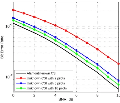
3.3.1.1 Simulation performance of unknown CSI
In this section the performance of a two transmit one receive STBC system is analyzed in
the presence of CSI estimation errors. Fig. 3.4 demonstrates the performance of 4-PSK
modulated STBC system with unknown flat Rayleigh fading channel. The graph shows
how the length of pilot symbols effect the estimation of the unknown channel at the receiver
as given by Cramer-Rao bound. The minimum value of the estimation error variance is
σε2 = N0 lEs
, (3.16)
wherel is the length of pilot symbols transmitted during training. The simulation is
per-formed by transmitting 104 frames of data symbols with a frame length of 130 symbols.
The results are analyzed by plotting the BER against multiple values of SNR
Fig. 3.5 demonstrates the performance of 8-PSK and 16-PSK modulated STBC system
with unknown channel parameters. The performance is shown to degrade with increasing
0 2 4 6 8 10 10−2
10−1
SNR, dB
Bit Error Rate
Alamouti known CSI Unknown CSI with 2 pilots Unknown CSI with 8 pilots Unknown CSI with 16 pilots
Figure 3.4: Performance of 4-PSK STBC system for different pilot length.
Fig. 3.6 demonstrates the performance of 4-QAM and 16-QAM modulated STBC
sys-tem with unknown channel parameters. QAM modulation is considered for the case of non
equal energy constellations. It is known from standard literature that, the performance of
higher amplitude modulation scheme is susceptible to high BER and it increases under the
0 2 4 6 8 10 10−1
SNR, dB
Bit Error Rate
Alamouti known CSI Unknown CSI with 2 pilots Unknown CSI with 8 pilots Unknown CSI with 16 pilots
(a) 8-PSK
0 2 4 6 8 10
10−1
Bit Error Rate
Alamouti known CSI Unknown CSI with 2 pilots Unknown CSI with 8 pilots Unknown CSI with 16 pilots
(b) 16-PSK
0 2 4 6 8 10 10−2
10−1
SNR, dB
Bit Error Rate
Alamouti known CSI Unknown CSI with 2 pilots Unknown CSI with 8 pilots Unknown CSI with 16 pilots
(a) 4-QAM
0 2 4 6 8 10
10−1
SNR, dB
Bit Error Rate
Alamouti known CSI Unknown CSI with 2 pilots Unknown CSI with 8 pilots Unknown CSI with 16 pilots
(b) 16-QAM
3.3.2
System model with unknown CFO
It is discussed in section 1.3.2, that in practical systems the receiver oscillator frequency
and the transmitter’s carrier frequency mismatches or is not perfectly synchronized. This
mismatch is known as CFO△fi,k which varies with different channels between ith trans-mit and receive antenna and with different sampling timesk, as shown in Table 3.2
Table 3.2: CFO distribution with channel and time
Time Channel 0 Channel 1
t=0 △f00 △f10 t+T △f01 △f11
Thus, the received baseband signal with CFO can be modeled as
rk= m∑−1
i=0
hiejϕi,ksi,k √
Es+nk (3.17)
whereϕi,k = 2π△fi,k/fsis the carrier angular frequency offset (CAFO) which is assumed to be a Gaussian RV with zero mean and varianceσ2
ϕandfsis the sampling frequency, sim-ilar to the assumptions made in [64, 65]. This representation is vastly used in literature [66]
and is only valid when assumed△fi,k ≪fs. Thus for a two branch STBC system, CAFO can be represented in a matrix form as
Φi,k =
ϕ00 ϕ10
ϕ01 ϕ11
(3.18)
In reality, the CAFO is unknown to the receiver and is estimated before detection.
Irrespec-tive of the type of estimator, the CAFO estimateϕˆi,k is modeled same as that of the channel
estimate in (3.11).
ˆ
The estimation errorϵi,k ∼ N(0, σϵ2)is considered a zero mean Gaussian RV. Since, the original value of CAFOϕi,k and the estimation errorϵi,k are independent of each other, the
imperfect estimate is also a Gaussian RVϕˆi,k ∼ N (
0, σ2 ˆ
ϕ )
.
To simplify the system model, let us substitutexi,k forhiejϕi,k. Therefore matrixXcan
be expressed as
X =
x00 x10
x∗11 −x∗01
=
h0ejϕ00 h1ejϕ10
(
h1ejϕ11
)∗
−(h0ejϕ01
)∗
. (3.20)
Thus the system model in (3.15) modifies to
˜s0
˜ s1
| {z }
˜
S
=
xˆ∗00r0+ ˆx10r1∗
ˆ
x∗11r0−xˆ01r1∗
| {z }
ˆ
XHR
=
ˆh∗0e−j
ˆ
ϕ00r
0+ ˆh1ej ˆ
ϕ11r∗
1
ˆ
h∗1e−jϕˆ10r
0−ˆh0ej ˆ
ϕ01r∗
1
(3.21)
Therefore, when the estimator is imperfect, it leaves behind estimation errors in the
detec-tion of the baseband signal. The simuladetec-tion demonstrates the deterioradetec-tion of the baseband
3.3.2.1 Simulation performance of unknown CFO
Fig. 3.7 demonstrates the performance of 4-PSK modulated STBC system for an
unsyn-chronized unknown carrier frequency offset and CSI.
0 2 4 6 8 10
10−2
10−1
100
SNR, dB
Bit Error Rate
Alamouti known CSI and CFO Unknown CSI with known CFO Unknown CSI with unknown CFO
Figure 3.7: Performance of unsynchronized 4-PSK STBC system under mismatch scenario.
Fig. 3.8 demonstrates the performance of 8-PSK and 16-PSK modulated unsynchronized
STBC system. The performance is shown to degrade with increasing modulation scheme.
The graphs shows how the system BER deteriorates when CSI is unknown and it gets worst
0 2 4 6 8 10 10−2
10−1 100
SNR, dB
Bit Error Rate
Alamouti known CSI and CFO Unknown CSI with known CFO Unknown CSI with unknown CFO
(a) 8-PSK
0 2 4 6 8 10
10−1 100
SNR, dB
Bit Error Rate
Alamouti known CSI and CFO Unknown CSI with known CFO Unknown CSI with unknown CFO
(b) 16-PSK
Figure 3.8: Performance of unsynchronized M-PSK STBC system under mismatch
0 2 4 6 8 10
10−2
10−1
100
SNR, dB
Bit Error Rate
Alamouti known CSI and CFO Unknown CSI with known CFO Unknown CSI with unknown CFO
Figure 3.9: Performance of unsynchronized 4-QAM STBC system under mismatch
sce-nario.
Fig. 3.9 is shown for the basic 4-QAM and demonstrates similar performance as that
of QPSK. Fig. 3.10 (a) and (b) demonstrates the performance of the STBC system for
16-QAM and 64-QAM respectively. QAM modulation is considered for the case of non
equal energy constellations. It is known from standard literature that, the performance of
higher amplitude modulation scheme is susceptible to high BER and it increases under the
0 2 4 6 8 10 10−1
100
SNR, dB
Bit Error Rate
Alamouti known CSI and CFO Unknown CSI with known CFO Unknown CSI and unknown CFO
(a) 16-QAM
0 2 4 6 8 10
100.1 100.2
SNR, dB
Bit Error Rate
Alamouti known CSI and CFO Unknown CSI with known CFO Unknown CSI and unknown CFO
(b) 64-QAM
sce-Chapter 4
STBC detection techniques
As a matter of fact, receiver is of utmost importance, because of its incredible task in a
WC system. It receive a signal for a fraction of time, observe and retrieve the baseband
signal from it, and make the best estimate of the transmitted signal. In the presence of
mul-tiplicative unknown channel coefficients and additive noise, the detection technique at the
receiver takes account of this decision making process and once in a while make occasional
errors. Thus, a best detector is the one, which is optimal in the sense of minimizing the
BER.
This chapter focuses on the detection schemes most prominently used at the receiver
for an optimal detection of the baseband signal. The subsections take into account the
unknown channel parameters and the CFO and follows the certainty equivalence principle
(CEP) for the purpose of design. The CEP states that the estimates of the uncertainties are
treated as if they were the true parameters and hence are used to derive the conventional
detection schemes. With this approach, we determine, that the conventional schemes give
4.1
Maximum Likelihood detector
Maximum Likelihood is a detection method based on a set of observations for a given
statistic by maximizing the likelihood function. Considering the system model presented
in (3.3), the received signalrkat thek-th instant and the channel fading parametershifrom
thei-th transmit antenna are taken as the observations, as shown in Fig. (4.1), whereas the
parameter to be detected is the transmitted signalsi,k.
Figure 4.1: Generic block diagram of a ideal ML detector with perfect estimation of
chan-nel parameters and no CFO.
4.1.1
ML System discription
The aim of a ML detector is to obtain the optimum value ofˆsi,k =si,ksuch that the posterior
probability of the transmitted signal conditioned on the observations is highest. Optimal
detection is obtained by choosing from a finite set of symbolsC ={c0, c1, ...}, depending
upon the type of modulation scheme used at the transmitter. This can be expressed as
si,k ,arg max
si,k ,arg max s∈C
{
P (si,k)P (rk|si,k, hi)
(rk)
}
, (4.2)
where the probability of receivingrkconditioned onhiand whensi,kis transmitted,P(rk|si,k, hi) is known as thelikelihoodfunction. Since we choose the value ofs∈ C,P(s)is a constant and hence it can be seen from (4.2), that maximizing the likelihood function maximizes the
MAP probability. Thus the decision rule for optimal detection becomes
si,k ,arg max
s∈C {P(rk|si,k, hi)}. (4.3) The probability distribution of the received signalrkcan be approximated to be of a
Gaus-sian RV as explained in [67]. The PDF of a GausGaus-sian RV is of the form
f(r) = √1 2πσ2
r
e
− |r−µr|
2
2σ2
r
, (4.4)
whereµris the mean andσr2is the variance. By taking the negative logarithm of the
likeli-hood function from (4.4), the decision metric in (4.3) becomes
si,k ,arg min
s∈C {−logP (rk|si,k, hi)}
= arg min
s∈C {
∥rk−hisi,k∥
2}
.
(4.5)
For the Alamouti’s STBC two branch MISO system, the ML decision metric for optimal
detection of the transmitted signal is
si,k ,arg min s∈C
{
|r0−h0s0−h1s1|2+|r1−h1s∗0+h0s∗1| 2}
. (4.6)
ML detection is widely in use for WC systems specially for MIMO. The performance of