ISSN(Online): 2320-9801
ISSN (Print) : 2320-9798
International Journal of Innovative Research in Computer
and Communication Engineering
(A High Impact Factor, Monthly, Peer Reviewed Journal)
Website: www.ijircce.com
Vol. 6, Issue 3, March 2018
Review Paper on Multi-Level Discrete
Wavelet Transform using Different Technique
Seemakant Sahu 1, Gurpreet Singh2
Research Scholar, Department of Electronics and Communication, Trinity Institute of Technology & Research, Bhopal, India1
Head of Department, Department of Electronics and Communication, Trinity Institute of Technology & Research, Bhopal, Bhopal, India 2
ABSTRACT: A comparative study are different types of discrete wavelet transform (DWT) architecture is presented in the paper. DWT is provide good resolution in both time and frequency. Many types of technique are designed into DWT architecture. But 2’s complement based design is the best design of other design. It is the main issue of this design in a number of full adder is more required. Overcome this problem is designed to canonic signed digit (CSD) has been applied DWT architecture to reduce the full adder. CSD based DWT architecture is suitable for many digital signal processing (DSP) applications. The overview of CSD technique presented in this paper.
KEYWORDS: Discrete wavelet transform (DWT), 2’s Complement technique, CSD technique
I. INTRODUCTION
The continuous development in laptop technology enhances using digital photos. Together with this comes the extreme problem of storing and moving the big amount of data representing the snap shots whilst uncompressed [1]. Multimedia records, i.e. audio and video require pretty a huge garage capability and transmission bandwidth. No matter of speedy growth in mass garage density, elevated speed of the processor and the overall performance of the virtual multimedia systems, the want for records storage capability and records transmission bandwidth preserve on increasing the abilities of new technology [1]. The Discrete Wavelet rework (DWT) has found many applications in virtual signal processing, because of the green computation and the sufficient residences for non-stationary signal analysis [2]. In recent times it has turned out to be one of the maximum used techniques for image compression. The photo is absolutely a form of redundancy statistics, i.e. it is composed the equal information from a unique attitude of view. By using the usage of records compression strategies, it's far practicable to get rid of a number of the redundant facts contained in the pix. Photo compression minimizes the size of a photograph file without degrading the exception of the image of an unacceptable stage. The discount in size of file lets in greater photos to be saved in a selected quantity of disk or memory area [3]-[5]. In this work, we have carried out the compression set of rules the use of primary Haar wavelet, in VHDL programming language. For that we have taken 8X8 matrix in both, on the way to lessen the complexity of information on the primary standards. This new arrival has proven a amazing promise towards information/photo compression. The contemporary JPEG2000 widespread is likewise primarily based on this remodel coding/algorithm [6]-[7]. On this painting, handiest grayscale picture are considered. However, wavelet transforms and compression strategies are similarly relevant to the color photos with 3 coloration components. We ought to apply this transform to each of this color factor independently and ought to treat the result as an array of vectors valued wavelet coefficients.
ISSN(Online): 2320-9801
ISSN (Print) : 2320-9798
International Journal of Innovative Research in Computer
and Communication Engineering
(A High Impact Factor, Monthly, Peer Reviewed Journal)
Website: www.ijircce.com
Vol. 6, Issue 3, March 2018
these techniques introduce a little power-performance tradeoff, causing architecture selection to be more complex and draw more attention. So, it is aimed to develop a methodology that is capable of minimizing power and area at the same time, subjected to given throughput and latency constraints [8].
II. DIRECTWAVELETTRANSFORM
The concept of discrete wavelet transform is introduced here [9]. Through the discrete wavelet transform analysis, the whole input value should be analyzed and further given to the process. The input data should be in the form of time domain. The DWT is used to change the input data from a time domain into a frequency domain [10, 11]. The frequency domains have many features and by the use of frequency domain it can easily identify the audio signal [12]. From the above steps details of DWT is known and now the continuous wavelet transform is studied. Here, the discrete wavelet transform is transmitted by a continuous wavelet transform and so a discussion on the continuous wavelet transform and its features has to be made. The continuous wavelet transform is a shifted version of the wavelet function Ȍ, and the main function of CWT is used to divide a continuous wavelet functions into a small wavelet.
The model used in [9] to implement the tree structure of Direct Wavelet Packet Transform (DWPT) is based on the filtering process. Figure 1 depicted a complete 3-level Direct WPT. In this figure G and H is the high pass and low pass filter respectively [13].
Computation period is the wide variety of the input cycles for one time produces output samples. In trendy, the computation duration is M= for a j-level DWPT. The duration of the 3-stage computation is eight. discern 1, The Sub band Coding set of rules for example, assume that the authentic sign X[n] has N- pattern points, spanning a frequency band of 0 to π rad/s. At the first decomposition level, the sign exceeded through the high pass and low bypass filters, followed through subsampling via 2. The output of the high pass filter out has N/2- sample factors (as a result half of the time resolution) however it handiest spans the frequencies π/2 to π rad/s (consequently double the frequency decision) [14].
ISSN(Online): 2320-9801
ISSN (Print) : 2320-9798
International Journal of Innovative Research in Computer
and Communication Engineering
(A High Impact Factor, Monthly, Peer Reviewed Journal)
Website: www.ijircce.com
Vol. 6, Issue 3, March 2018
The output of the low-bypass filer additionally has N/2- sample points, but it spans the opposite half of the frequency band, frequencies from 0 to π /2 rad/s. again low and excessive-pass filter output passed via the identical low skip and excessive pass filters for similarly decomposition [11, 12].
The output of the second one low skip clear out followed by way of sub sampling has N/4 samples spanning a frequency band of zero to π /4 rad/s, and the output of the second high bypass filter out observed by using sub sampling has N/4 samples spanning a frequency band of π /four to π /2 rad/s. the second one excessive bypass filtered sign constitutes the second stage of DWPT coefficients. This sign has half of the time resolution, but two times the frequency decision of the first level sign. This process continues till two samples are left. For this specific instance there would be three ranges of decomposition, each having half of the range of samples of the preceding degree. From the above steps details of DWT is known and now the continuous wavelet transform is studied. Here, the discrete wavelet transform is transmitted by a continuous wavelet transform and so a discussion on the continuous wavelet transform and its features has to be made. The continuous wavelet transform is a shifted version of the wavelet function Ȍ, and the main function of CWT is used to divide a continuous wavelet functions into a small wavelet.
The DWT of the original signal is then obtained by concatenating all coefficients starting from the last level of decomposition (remaining two samples, in this case). The DWT will then have the same number of coefficients as the original signal [15].
III. LITERATUREREVIEW
Rakesh Biswas et al. [1], this paper presents a high precision low area lifting based architecture for the unified implementation of both lossy and lossless 3D multi-level Discrete Wavelet Transform (DWT) using LeGall 5/3 wavelet and Cohen-Daubechies-Feauveau (CDF) 9/7 wavelet. The proposed system is parallel-pipelined, and resource is shared between the lossy and lossless modes, producing a throughput of 2 outputs/clock and achieving a high speed and low area solution. The data width of the design is taken as 20 bits to reach a high PSNR value for multi-level 3D DWT. Targeting a portable and real-time solution, the proposed architecture was successfully implemented on Xilinx Virtex-5 series Field Programmable Gate Array (FPGA), achieving a clock speed of 290 MHz with a power consumption of 467 mWat 200 MHz clock frequency. The design has also been implemented in UMC 90 nm CMOS technology, which consumes 329 mW power at 200 MHz clock frequency. The proposed solution may be configured as lossless or lossy compression, in the field of 3D image compression system, according to the necessity of the user.
Linning Ye et al. , “Memory Efficient Multilevel Discrete Wavelet Transform Schemes for JPEG2000”, [2], when working with the line-primarily based wavelet transform, JPEG2000 wishes to buffer many sub-band lines for future block coding. This coding buffer occupies most people of the reminiscence utilization in a JPEG2000 gadget. On this paper, we first use the multilevel blockprimarily based wavelet remodel, after which make use of the multilevel stripe-based wavelet remodel to recognise JPEG2000 coding. The system schemes of the multilevel block-stripe-based totally wavelet remodel and the multilevel stripe-based totally wavelet transform for JPEG2000 are provided. The proposed schemes can effectively control the wavelet coefficient output sample, and thus lessen the reminiscence usage of JPEG2000 coding buffer. compared with the line-based totally wavelet remodel, the proposed schemes reduce greater than 50% reminiscence usage of the JPEG2000 system and slightly decrease the memory bandwidth. via preserving the blocks/stripes in on-chip memory, which do no longer depend upon the photo length, the reminiscence bandwidth of the JPEG2000 system can be in addition significantly decreased. The gain of the stripebased wavelet remodel over the block based wavelet remodel lies in that it occupies an awful lot much less inner memory.
ISSN(Online): 2320-9801
ISSN (Print) : 2320-9798
International Journal of Innovative Research in Computer
and Communication Engineering
(A High Impact Factor, Monthly, Peer Reviewed Journal)
Website: www.ijircce.com
Vol. 6, Issue 3, March 2018
encoding technique and offers better compression ratio. by the usage of the above algorithms the calculation of height signal to noise ratio(PSNR), suggest rectangular errors(MSE) and compression ratio(CR) and Bits in step with pixel(BPP) of the compressed image via giving 512×512 input pictures and also the comparison of performance analysis of the parameters with that above algorithms is finished. The result really explains that Fractal set of rules affords higher Compression ratio (CR) and top signal to noise ratio (PSNR).
Rashmita Sahoo et al., “Haar Wavelet Transform Image Compression using Run Length Encoding”, [4], in present day generation memory storing area is not a completely big deal. however when it comes to a transportable gadget i.e. a digital digicam with net in addition to communication facility, then the bandwidth for communique as well as storage are of serious issue. Huge beneficial statistics must be stored and retrieved efficaciously for realistic functions. The Haar wavelet, which is the handiest of all of the 2d DWT, in conjunction with thresholding has been carried out on a JPEG photo. After that Run duration Entropy Coding has been adopted. that is the novel method that authors have proposed for compression of image the usage of parameter CR (Compression Ratio) without dropping the parameter PSNR, the first-class of picture, the use of less bandwidth.
B. Ramkumar et al., “Low-Power and Area-Efficient Carry Select Adder”, [5], carry Select Adder (CSLA) is one of the quickest adders utilized as a part of numerous information handling processors to perform quick number juggling capacities. From the structure of the CSLA, it is clear that there is extension for diminishing the zone and force utilization in the CSLA. This work utilizes a straightforward and proficient entryway level change to altogether diminish the range and force of the CSLA. In light of this change 8-, 16-, 32-, and 64-b square-root CSLA (SQRT CSLA) structural engineering have been produced and contrasted and the general SQRT CSLA structural planning. The proposed outline has diminished territory and force as contrasted and the standard SQRT CSLA with just a slight increment in the deferral. This work assesses the execution of the proposed outlines regarding deferral, region, power, and their items by hand with legitimate exertion and through specially craft and format in 0.18-m CMOS process innovation. The outcomes investigation demonstrates that the proposed CSLA structure is superior to the normal SQRT CSLA.
IV. LOW-COMPLEXITYDESIGNSFORDWT
DWPT computation is nothing but two-channel FIR filter computation. Low-pass and high-pass down sampled filter computations are performed on the input to calculate the DWPT coefficients. Low-pass down sampled filter is the average between two samples and high-pass filter is the difference b/w two samples. The DWPT algorithms for 1-level decomposition are given as;
(1) (2)
Where x(n) is the input and & are respectively the low-pass and high-pass DWPT coefficients, h[n] and g[n] are respectively, the low-pass and high-pass filter coefficients. We have assumed the Daubechies four tap (Daub-4) filter coefficients for the low-pass filter proposed design. However, similar type of design can be derived for other type of wavelet filters as well. The Daub-4 low-pass filter coefficients are taken from [7]. The corresponding high-pass filter coefficients are calculated using the following relation:
ISSN(Online): 2320-9801
ISSN (Print) : 2320-9798
International Journal of Innovative Research in Computer
and Communication Engineering
(A High Impact Factor, Monthly, Peer Reviewed Journal)
Website: www.ijircce.com
Vol. 6, Issue 3, March 2018
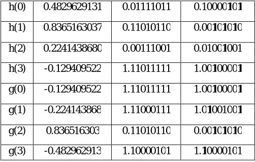
Table 1: Low and high-pass Daub-4 filter coefficients. The binary digit 1 shown in bold face represents -1 of the CSD digit
h(0) 0.4829629131 0.01111011 0.10000101 h(1) 0.8365163037 0.11010110 0.00101010
h(2) 0.2241438680 0.00111001 0.01001001 h(3) -0.129409522 1.11011111 1.00100001
g(0) -0.129409522 1.11011111 1.00100001 g(1) -0.224143868 1.11000111 1.01001001
g(2) 0.836516303 0.11010110 0.00101010 g(3) -0.482962913 1.10000101 1.10000101
Where, h(n) and g(n) are, respectively, the low and high-pass filter coefficients. N is the filter order. The 8 bit 2’complement and CSD representation of the low and high-pass filter coefficient are given in table1. Equation can be rewritten four-tap FIR filter as:
(4)
(5)
Where operator represents one sample delay in Z-domain.
V. PROPOSED ARCHITECTURE
On this paper, the original signal X[n] has N- sample points, is exceeded thru 1×2 demultipler. whilst pick out line is 0 then we get even pattern and whilst choose line is 1 then we get abnormal sample. After that we've got handed those samples through CSD based totally low-skip filter out, equal method with high-skip filter. Now we get N/2 sample s at the primary decomposition level output of CSD primarily based high-skip (Y_H) and low-pass filter out (Y_L). At the second decomposition level, the output of CSD based totally low-skip and high-bypass clear out handed through a sign in unit. Now the output of sign up unit surpassed via mux. whilst the pick line 0, we get CSD primarily based low-skip filter out output and while the choose line 1, we get CSD primarily based high-skip filter out. Now we've surpassed mux output via CSD primarily based low-pass filter out then we get Y_LL &Y_LH output now equal method implemented with the CSD based high-skip filter out we get Y_HL & Y_HH. on the 0.33 decomposition degree, the time period is doubled and frequency can be 1/2, and the output of CSD primarily based low-pass and excessive-skip filter out is passed through a check in unit. Now the output of check in unit is surpassed via mux. when the choose line is 00. Now finally we have passed mux output through CSD based low pass filter and high pass filter we get
ISSN(Online): 2320-9801
ISSN (Print) : 2320-9798
International Journal of Innovative Research in Computer
and Communication Engineering
(A High Impact Factor, Monthly, Peer Reviewed Journal)
Website: www.ijircce.com
Vol. 6, Issue 3, March 2018
VI. SIMULATIONRESULT
We have implemented multiplier based (MB) architecture and common Boolean logic based (CBL) architecture for DWT by different approaches. The delay and area evaluation methodology considers all gates to be made up of AND, OR, and Inverter (AOI), each having delay equal to 1 unit and area equal to 1 unit. We then add up the number of gates in the longest path of a logic block that contributes to the maximum delay. The area evaluation is done by counting the total number of AOI gates required for each logic block.
VII. CONCLUSION
We have used the CSD number system to represent the filter coefficients of the wavelet filter with minimum number of ones. Consequently, the number of FAs of the design will be reduced by nearly 50% of these of the 2’s complement design. Then we carried out the CBL technique to similarly reduce the electricity and location. on this structure the velocity of the enter sampling extended and used of the low and excessive skip filter. Low pass clear out is the average between sample and high skip clear out is the difference among two samples. there's no on-chip reminiscence and memory get right of entry to at some stage in the computation, so which can reap widespread discount in each die region and power dissipation.
on this paper architecture is appropriate for excessive velocity online applications. With this architecture the speed of the wavelet packet transforms is increased, occupied regions of the circuit is reduced about 50% in the previous convolution primarily based structure and decreases the electricity approximately 15-25% inside the previous convolution based totally structure. It has 100% hardware utilization efficiency.
Reg unit
Mux unit
CG
CH 1×2
1×2
CH
CG
Reg Unit
Mux unit
Reg unit
Mux unit
CG
Reg unit
Mux unit
CH
ISSN(Online): 2320-9801
ISSN (Print) : 2320-9798
International Journal of Innovative Research in Computer
and Communication Engineering
(A High Impact Factor, Monthly, Peer Reviewed Journal)
Website: www.ijircce.com
Vol. 6, Issue 3, March 2018
REFERENCES
[1] Rakesh Biswas, Siddarth Reddy Malreddy and Swapna Banerjee, “A High Precision-Low Area Unified Architecture for Lossy and Lossless 3D Multi-Level Discrete Wavelet Transform”, Transactions on Circuits and Systems for Video Technology, Vol. 45, No. 5, May 2017. [2] Linning Ye and Zujun Hou, ―Memory Efficient Multilevel Discrete Wavelet Transform Schemes for JPEG2000‖, IEEE Transactions on
Circuits and Systems for Video Technology, Vol. 25, No. 11, November 2015.
[3] R. Praisline Jasmi and Mr. B. Perumal, ―Comparison of Image Compression Techniques using Huffman Coding, DWT and Fractal Algorithm‖, 2015 International Conference on Computer Communication and Informatics (ICCCI -2015), Jan. 08 – 10, 2015, Coimbatore, INDIA.
[4] Rashmita Sahoo, Sangita Roy, Sheli Sinha Chaudhuri, ―Haar Wavelet Transform Image Compression using Run Length Encoding‖,
International Conference on Communication and Signal Processing, April 3-5, 2014, India.
[5] B. Ramkumar and Harish M Kittur, ―Low-Power and Area-Efficient Carry Select Adder‖, IEEE Transactions on Very Large Scale
Integration (VLSI) Systems, VOL. 20, NO. 2, February 2012.
[6] Ms. Rashmi Patil and Dr. M.T. Kolte, “Low Power High Speed VLSI Architecture for 1-DDiscrete Wavelet Transform”, 978-1-4799-7678-2/15/$31.00 ©2015 IEEE.
[7] Gaurav Tewari, Santu Sardar, K. A. Babu, ”High-Speed & Memory Efficient 2-D DWT on Xilinx Spartan3A DSP using scalable Polyphase Structure with DA for JPEG2000 Standard,” 978-1-4244-8679-3/11/$26.00 ©2011 IEEE.
[8] Asmita Haveliya, “Design and Simulation of 32-Point FFT Using Radix-2 Algorithm for FPGA Implementation”, Second International Conference on Advanced Computing & Communication Technologies IEEE 2012.
[9] L. Sriraman, T. N. Prabakar, “Design and Implementation of Two Variable Multiplier Using KCM and Vedic Mathematics”, 1" In!' I Conf. on Recent Advances in Information Technology I RAIT -2012.
[10] Honey Durga Tiwari, Ganzorig Gankhuyag, Chan Mo Kim and Yong Beom Cho, “Multiplier design based on ancient Indian Vedic Mathematics”, 978-1-4244-2599-0/08/$25.00 ©2008 IEEE.
[11] Gaurav Tewari, Santu Sardar, K. A. Babu, ”High-Speed & Memory Efficient 2-D DWT on Xilinx Spartan3A DSP using scalable Polyphase Structure with DA for JPEG2000 Standard,” 978-1-4244-8679-3/11/$26.00 ©2011 IEEE.
[12] S.G. Mallat, “A Theory for Multiresolution Signal Decomposition: The Wavelet Representation”, IEEE Trans. on Pattern Analysis on Machine Intelligence, 110. July1989, pp. 674-693.
[13] M. Alam, C. A. Rahman, and G. Jullian, ”Efficient distributed arithmetic based DWT architectures for multimedia applications,” in Proc.
IEEEWorkshop on SoC for real-time applications, pp. 333 336, 2003.
[14] M. Martina, and G. Masera, ”Low-complexity, efficient 9/7 wavelet filters VLSI implementation,” IEEE Trans. on Circuits and Syst. II,
ExpressBrief vol. 53, no. 11, pp. 1289-1293, Nov. 2006.
[15] M. Martina, and G. Masera, ”Multiplierless, folded 9/7-5/3 wavelet VLSI architecture,” IEEE Trans. on Circuits andsyst. II, Express Brief