Effects of Loading Conditions and Types of Motion on PWR Fuel Rod Cladding
Wear
Joulin T.P.(1), Guérout F.M.(1), Lina A.(2) and Moinereau D.(2)
(1) AECL, Chalk River, Canada
(2) Electricité De France, Les Renardières, France
ABSTRACT
The objective of this study was to investigate the effects of the types of motion and loading conditions on the wear of Pressurized Water Reactor (PWR) fuel rod cladding made of Zircaloy-4 in contact with a grid support cell. Fretting-wear tests, for various combinations of motion and static force applied, were conducted at 310ºC and 11.7 MPa using primary circuit water chemistry. Scanning Electron Microscope (SEM) examinations were performed on the worn fuel rod cladding specimens to identify wear mechanisms. Wear coefficients were used to assess the severity of the wear process. The types of motion and the loading conditions were found to have a significant interdependent effect on fuel rod wear coefficients.
INTRODUCTION
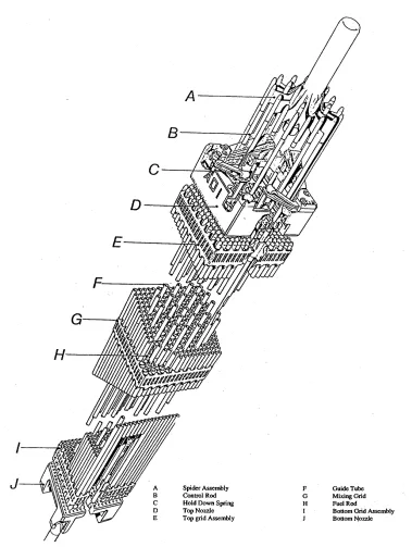
Wear occurs in mechanical equipment, often causing malfunctioning, vibration, and clearance increase; thus, leading to the reduction of equipment lifetime. Therefore, reduction of wear is an important economic factor for industry. In the nuclear reactor environment, wear problems usually result from flow-induced vibration of tubular structures, both in the primary and secondary systems of the reactors. Flow-induced vibration of fuel assemblies (Figure 1) in PWR power plants can result in severe wear of fuel rod cladding against grid assemblies. As part of an extensive research program to better understand the wear of fuel assemblies, Electricité De France (EDF) recently funded a fretting-wear test program at AECL’s Chalk River Laboratories (CRL). Prior to this study, experiments were conducted at EDF laboratories in the Mechanics and Technology of Components (MTC) Branch to determine the set of typical test conditions to be then used by AECL. All AECL tests were performed using real PWR components under normal reactor conditions observed in France.
The objectives of this study were to derive wear coefficients for various fuel rod motions and develop a better understanding of in-reactor fuel rod cladding wear mechanisms (using the SEM).
CANFRET machines, designed and manufactured by AECL, are used at CRL and at other fretting-wear laboratories to derive wear coefficients for nuclear reactor components. Up to now, transverse sliding, orbital sliding, normal impacting, and impact/sliding motions could be generated. One of these machines was modified to study the effects of axial, transverse, and bi-directional motions (combined axial and transverse motions) on fuel rod wear. These tests were conducted with static forces (preloads) of 0.1, 1, and 2 N, forcing the fuel rod specimen to remain in contact with one land of the grid cell (contact was maintained on arches). The configuration chosen is typical of fuel rod/spacer grid loading conditions that exist early in the fuel cycle.
FRETTING-WEAR TESTING FACILITY
Fretting-wear of nuclear reactor components has been studied through experiments at AECL for more than 20 years. Several fretting-wear machines have been manufactured at CRL. The test facility currently consists of nine CANFRET machines in which temperature, pressure, and water chemistry can b e independently controlled.
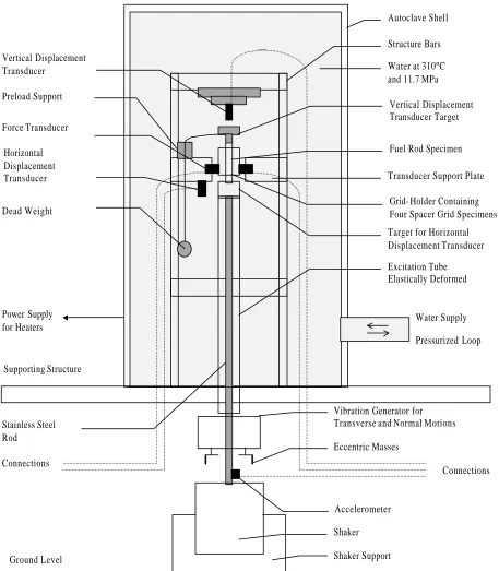
Each CANFRET machine consists of an autoclave shell, an excitation tube, a transducer support plate, a vibration generator, and a supporting structure. A vibration generator attached to the end of an excitation tube provides interaction at the wear specimen location. This tube protrudes outside the autoclave through a flexible sleeve. The machines are connected to a pressurized loop with an accumulator, a water storage tank, a make-up pump, and process instrumentation for temp erature and pressure control. Either pressurized water or saturated steam conditions can be achieved. The operating temperature and pressure limits are 320°C and 11.7 MPa. There is neither recirculation of water nor any once-through flow.
The relative tube-to-support motion during operation is monitored using two high-temperature eddy-current displacement probes. These are mounted to the bottom of the instrumentation platform. The machines contain a high-temperature force measuring system consisting of four piezoelectric force transducers. These transducers are located within the instrument platform at 90° increments around the outside circumference of the support specimen.
A computer system acquires and analyses the displacement and force signals. An AECL proprietary software
SMiRT 16, Washington DC, August 2001 Paper # 1239
Figure 1: PWR Fuel Assembly
package called WRAP (Work-Rate Analysis Program), based on the LabVIEW® data analysis package, is used to compute output parameters such as number of impacts, RMS forces, tube-to-support clearances, sliding distances and work-rates.
of the vertical displacement. A circular target, made of stainless steel, was fixed on the top of the excitation tube to provide good quality measurements. A preload was applied to simulate the early fuel rod/spacer grid configuration where no clearance exists between the fuel rods and grids. A photograph of the top portion of the modified machine is shown in Figure 3.
Figure 2: Schematic of the Bi-Directional CANFRET Machine
Shaker Support
Autoclave Shell
Structure Bars
Transducer Support Plate Water at 310ºC
and 11.7 MPa
Excitation Tube Elastically Deformed
Vertical Displacement Transducer Target
Water Supply
Pressurized Loop Power Supply
for Heaters
Connections Connections
Shaker Accelerometer Eccentric Masses Vibration Generator for Transverse and Normal Motions
Fuel Rod Specimen
Grid- Holder Containing Four Spacer Grid Specimens Vertical Displacement
Transducer
Preload Support
Force Transducer
Horizontal Displacement Transducer
Dead Weight
Ground Level Supporting Structure
Stainless Steel Rod
Figure 3: Photograph of Top Portion of Modified CANFRET Machine
WEAR COEFFICIENT CALCULATION
The measurement of forces and displacements allows for the computation of work-rates. Work-rate (
W
&
) is a parameter introduced by Frick et al. [1] to quantify the rate of energy dissipated at the contact. It is a quantity derived from normal force (Fn), sliding distance (s), and sample time (t) and is expressed as:&
W
1
t
F ds
n=
∫
(1)Work-rate, as defined in Equation 1, is used to normalize wear rate. The calculation of the wear rate (
V
&
) is based on the wear volume, provided by profilometry analysis. Equation 2 shows the relationship between wear rate and work-rate derived from Archard’s Law [2]. This relationship is used to define a dimensional wear coefficient (K) whose units are m2/N or Pa-1:K =
V
W
&
&
(2)TEST CONDITIONS
Table 1 shows the results for all the tests conducted in this study in terms of wear volumes, wear rates and wear coefficients.
Table 1: Wear Results
Test # Type of Preload Wear Volume Wear Rate Work-Rate Wear Coefficient
(*) Motion Applied (N) (mm3) (µm3/s) (mW) (x 10-15 Pa-1)
1T transverse 0.1 0.0031 4.3 0.106 41
2T transverse 1 0.0028 3.9 1.04 4
3T transverse 1 0.0054 7.5 0.99 8
4T transverse 2 0.0002 0.3 2.12 0.1
5T transverse 2 0.0001 0.1 2.05 0.05
4A axial 0.1 0.0103 14.3 0.07 204
5A axial 0.1 0.0008 1.1 0.18 6
6A axial 1 0.0009 1.2 0.39 3
7A axial 1 0.007 9.7 0.31 31
8A axial 2 0.0063 8.8 0.76 12
9A axial 2 0.0011 1.5 0.99 2
10B bi-directional 0.1 0.0061 8.5 0.57 15
11B bi-directional 0.1 0.034 47.2 1.33 36
12B bi-directional 1 0.124 172.2 0.93 185
13B bi-directional 1 0.006 8.3 1.92 4
14B bi-directional 2 0.0055 7.7 3.06 3
15B bi-directional 2 0.006 8.3 3.88 2
(*) The letter after the number refers to the type of motion applied
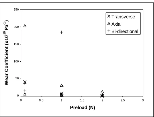
Figure 4 shows the effects of preload and motion on the wear coefficient. The wear coefficient is higher for low-preload tests (0.1 and 1 N) than for high-low-preload tests (2 N). For 0.1 N low-preload tests, intermittent lift -off occurred. The effect of the types of motion on the wear severity is strongly dependent upon the preload applied.
0 50 100 150 200 250
0 0.5 1 1.5 2 2.5 3
Preload (N)
Wear Coefficient (x10
-15
Pa
-1 )
Transverse
Axial
Bi-directional
Actual Motions
Due to the loading conditions, the input motion (transverse, axial or bi-directional) is different from the actual motion occurring at the contact location. The results can be reorganised in three categories corresponding to the three kinds of actual motion that took place, as shown below in Table 2. Organising the results by actual motion helps to understand the different wear regimes observed but significant scatter is still observed between results within each category (i.e., between 4A and 5A).
For all 0.1 N preload tests, intermittent lift -off occurred. The low preload did not maintain permanent contact between the fuel rod and the arch. However while the rod was in contact, sliding motion occurred. These tests resulted in an actual motion referred to as "intermittent sliding" in Table 2.
For higher preload tests (1 and 2 N), the actual motion observed was unidirectional sliding, referred to as "pure sliding" in Table 2. Within this category, for the 1 N preload tests, the unidirectional input motion was the actual motion observed. However, one of the bi-directional motion tests with a 1 N preload (13B) is also in this category since the axial motion dominated the transverse motion, resulting in a wear coefficient comparable to the other unidirectional motion tests with the same preload. All of the 2 N preload tests are in the "pure sliding" category as well. For the transverse motion tests conducted with a 2 N preload, the arch acted as a pivot, limiting significantly the motion amplitude. This situation did not occur for the axial and bi-directional motion tests because the axial excitation input force was much greater than the transverse input force; thus, for these four tests, the axial input motion was the actual motion that occurred at the contact location.
The second bi-directional motion test conducted with a 1 N preload forms its own category, resulting in the highest wear coefficient. The actual motion was the bi-directional input motion.
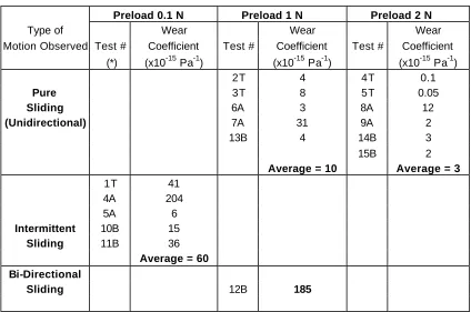
Table 2: Wear Results Grouped by Type of Motion and Preload
Preload 0.1 N Preload 1 N Preload 2 N
Type of Wear Wear Wear
Motion Observed Test # Coefficient Test # Coefficient Test # Coefficient
(*) (x10-15 Pa-1) (x10-15 Pa-1) (x10-15 Pa-1)
2T 4 4T 0.1
Pure 3T 8 5T 0.05
Sliding 6A 3 8A 12
(Unidirectional) 7A 31 9A 2
13B 4 14B 3
15B 2
Average = 10 Average = 3
1T 41
4A 204
5A 6
Intermittent 10B 15
Sliding 11B 36
Average = 60
Bi-Directional
Sliding 12B 185
(*) The letter after the number refers to the type of motion applied (Table 1)
Effect of Actual Motion on the Wear Coefficient
Table 2 can be summarized as follows (given in a descending order of wear severity):
- Pure sliding, 1 N preload, 5 tests, wear coefficient of 10 x 10 Pa ; and, - Pure sliding, 2 N preload, 6 tests, wear coefficient of 3 x 10-15 Pa-1.
A ratio of almost 20 was found between the wear coefficients for the bi-directional motion test and the unidirectional motion tests for an identical preload of 1 N. This trend has already been shown by Guérout et al. [3].
For all 0.1 N preload tests, intermittent sliding occurred. The wear coefficients are smaller than the one found for bi-directional sliding. The lift-off seems to inhibit the potential wearing effect of bi-directional motion. The wear coefficients of the 0.1 N preload tests are higher than those found for pure sliding. This is in agreement with results of Ko et al. [4] and Fisher et al. [5].
The wear coefficient for bi-directional sliding is larger than the one for intermittent sliding. Both situations could occur in reactor. Due to thermal expansion and spring relaxation, bi-directional sliding could change to intermittent sliding.
SEM examination was performed on the fuel rod cladding specimens prior to profilometry analysis. The wear damage observed on all of the wear marks was small.
Intermittent Sliding (0.1 N Preload)
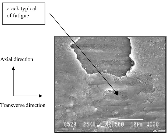
The low preload did not maintain the fuel rod in permanent contact with the grid. Intermittent lift-off occurred, resulting in flat-hammered areas (Figure 5). Plastic deformation in the transverse direction, adhesion and some fatigue (Figure 6) occurred. Fatigue, usually a more penalizing wear mechanism, might explain why the wear coefficients are relatively large with a low preload.
Bi-directional Sliding (1 N Preload)
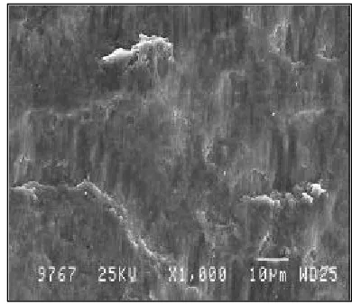
The preload was large enough to maintain permanent contact between the fuel rod and grid. Plastic deformation was observed. Scratches typical of abrasive wear were observed locally (Figure 7). Abrasion usually results in severe wear, which most likely explains why the wear coefficient is the largest for a bi-directional sliding with a 1 N preload. Some marks of adhesion were noted as well.
Pure Sliding (1 N and 2 N Preload)
The fuel rod was in permanent contact with the grid. Transverse motion tests with a 2 N preload showed almost no wear since the fuel rod was stuck against the arch (due to the high preload and the low input force). The main wear mechanism observed for the axial motion tests was plastic deformation oriented in the axial direction (Figure 8). The wear patterns of the bi-directional motion tests are very similar to those of the axial motion tests. No marks of transverse motion could be seen for the bi-directional motion tests.
Figure 5: Flat-Hammered Surface (x250) Figure 6: Removal of a Flake of Material (x2500) - Damage Typical of Plastic Deformation - Damage Typical of Fatigue
crack typical of fatigue
Axial direction
Figure 7: Scratch in the Transverse Direction (x1000) Figure 8: Marks in the Axial Direction (x1000) - Surface Damage Typical of Abrasive Wear - Surface Damage Typical of Plastic Deformation
CONCLUSION
The effect of the types of motion on the wear severity is strongly dependent upon t he preload applied. The largest wear coefficient was found for a bi-directional sliding motion test with a 1 N preload. Intermittent sliding (due to a low preload, 0.1 N) motion tests showed relatively large wear coefficients. Pure sliding motion tests, with a 1 or 2 N preload, resulted in the lowest wear coefficients.
The wear coefficient of the bi-directional motion test was about 20 times larger than those of unidirectional motion tests for an identical preload of 1 N.
The lift-off of the fuel rod, occurring for tests conducted with a 0.1 N preload, inhibited the effect of bi-directional motion. The wear coefficients in this case were greater than those observed for pure sliding.
The wear coefficient for bi-directional sliding was larger than that for intermittent sliding.
SEM examination of the worn surfaces of the fuel rod specimens showed the dominant wear mechanisms. The severity of the wear patterns observed was in good agreement with the level of wear damage in terms of wear coefficient.
ACKNOWLEDGEMENTS
The lead author thanks Dr. I.G. Currie at the University of Toronto and M.J. Pettigrew at AECL for their support and encouragement.
REFERENCES
1. Frick, T.M., Sobek, T.E. and Reavis, J.R., "Overview on the Development and Implementation of Methodologies to Compute Vibration and Wear of Steam Generator Tubes," ASME Special Publication: Symposium on Flow-Induced Vibrations: Vol. 3 – Vibration in Heat Exchangers, 1984, pp. 149–161.
2. Archard, J.F., "Contact and Rubbing of Flat Surfaces," Journal of Applied Physics, Vol. 24, 1953, p. 24.
3. Guérout, F.M., Grandison D.A.E., "Effect of Fuel Element Motion on Pressure Tube Fretting-Wear of CANDU Reactors," Transactions of the 14th International Conference on Structural Mechanics in Reactor Technology, Vol. IX, paper L06/1, August 1997, pp. IX-173-IX-181.
4. Ko, P.L., "Wear of Zirconium Alloys due to Fretting and Periodic Impacting," ASME, 1979, pp. 388-395.
5. Fisher, N.J., Weckwerth, M.K., Grandison D.A.E., Cotnam, B.M., "Fretting-Wear of Zirconium Alloys," Transactions of the 14th International Conference on Structural Mechanics in Reactor Technology, Vol. IX, paper L06/2, August 1997,
Axial direction