Experimental Study of Heat Pipe Performance
in LHTES with Effect of Fill Ratio
Chandrakishor Ladekar1, S. K. Choudhary2, S. S. Khandare3
Research Scholar, Department of Mechanical Engineering, B. D. College of Engineering, Wardha, Maharashtra, India
& Assistant Professor, Department of Mechanical Engineering, PCCOE, Pune, Maharashtra, India1
Professor, Department of Mechanical Engineering, K. D. K. College of Engineering, Nagpur, India2
Ex. Principal (Retired), B. D. College of Engineering, Wardha, Maharashtra, India3
ABSTRACT: The work has been undertaken to experimentally study performance of heat pipe in latent heat thermal energy storage (LHTES), with different working fluid fill ratio of heat pipe. Fill ratio is defined as the mass of working fluid required to charge heat pipe for maximizing the rate of heat transfer. Heat pipe was designed for its application in LHTES and the performance of heat pipe was tested by varying heat pipe charging mass of working fluid against its designed value. Designed value of heat pipe working fluid fill ratio depends on number of parameters, a numerical model designed to find fluid fill ratio. Experiment with flow rate of 10 lit./min. was conducted for different fill ratio of 80%, 90%, 100%, 110% & 120% and charging discharging of LHTES was tested. With increasing mass of charging fluid filled in heat pipe the rate of heat transfer increases but the evaporator temperature decreases. Significant effect of decreasing fill ratio is seen in charging and discharging process of heat pipe embedded LHTES. Drastic change in discharging time due to change in fill ratio and discharging time reduces by 40%. Heat transfer between heat transferring fluid (HTF) and phase change material (PCM) increases with decreasing fill ratio below design value but adverse effect of more charging is not much significant.
KEYWORDS:LHTES; PCM; Heat Pipe; Optimization of heat pipe; Fill ratio.
I. INTRODUCTION
Vol. 5, Issue 12, December 2016
Copyright to IJIRSET DOI:10.15680/IJIRSET.2016.0512056 21240
II. LITERATURESURVAY
The idea of the heat pipe was first suggested by Gauler in 1942 and later by Grover in the early 1960s suggested remarkable properties of the heat pipe and serious development work took place. W.S. Lee et al. [4] developed a low temperature LHTES system operating with a variety of PCMs that utilized a two-phase thermosiphon operating with ethyl alcohol as the working fluid. LHTES, with copper–water heat pipes embedded within a rectangular PCM enclosure was developed and tested show improvement in both melting and solidification [5-9]. R. M. Patil and C. L. Ladekar [10] experimentally investigated the performance of LHTES using embedded Heat pipes in comparison with LHTES with embedded copper pipes and found decrease in charging and discharging time for LHTES. S. Shandilya and C. L. Ladekar [11] tested performance of LHTES experimentally with use of PCM of different grades and found charging and discharging time decrease with PCM with low melting point but at the same time the storage capacity decrease also LHTES with embedded heat pipe is found to be more effective that LHTES with embedded copper pipe. Reda I. ElGhnam et al. [12] studied effect of parameters like the size and material of the spherical capsule, the volume flow rate and temperature of the HTF on the time for complete charging/discharging. Shuangfeng Wang et al. [13] saw the effect of evaporation section and condensation section length on thermal performance of flat plate heat pipe. Ravi S. Prasher [14] put forward a conduction based model to assess the heat transport capability of heat pipes and vapor chamber for various configurations. B. K. Tan et al. [15] introduced an analytical approach to study the liquid flow performances inside the wick structure of a flat plate heat pipe under different heat source conditions. Y. Koito et al. [16] investigated heat transfer characteristics of heat sinks with flat plate heat pipe. Nat Thuchayapong et. al. [17] analyzed the effect of capillary pressure on performance of a heat pipe using numerical approach with FEM. Xiaohong Gui et. al. [18] investigates influence of void ratio on thermal performance of heat pipe receiver. C.W. Chan et. al. [19] reviewed diverse types of heat pipes, types of wicks, working fluid and emphasis that all these topics are relevant to the improvement of heat pipe performance. Te-En Tsai et. al [20] developed dynamic test method for determining the thermal performances of heat pipes and tested the effect bending angle , fill ratio and shape of pipe. Comparison between the steady-state test and the dynamic test are found to be remarkably analogous. Chandrakishor Ladekar et.al [21] critically reviewed all the parameters of heat pipe for its effect on heat transfer in LHTES and suggested suitable materials for LHTES. Chandrakishor Ladekar et. al [22] tested effect of fill ration, heat pipe diameter, evaporator & condenser length on the charging and discharging process in the LHTES.
Several works on heat pipe use 1-D or 2-D models to study the heat pipe transient behaviours. Peterson [23] suggested that assuming uniform temperature at any given point in time the heat pipe can be typically modeled using a lumped capacitance method. Faghri [24] suggested a 2-D mathematical transient model of heat pipes. He took account of the interfacial convective heat flux at liquid–vapor interface, and assumed the vapor flow as compressible flow, the temperature profile across the wick is linear, and a nonslip condition and zero flow velocity at the end caps. He used his model to simulate the temperature distributions when the heat pipe is subjected to non-uniform input heat flux such as pulsed heat input or multiple heat source or heat sinks. Murer et al. [25], however, assumed an incompressible flow in the vapor phase and a neglected energy transfer rate through the liquid phase in the axial direction.
He gave a 1-D model to simulate the wall temperature, vapor pressure, and mass flow rate evolutions of the tested heat pipes. Faghri and Harley [26] proposed a representative 1-D model, they took the heat pipe as a lumped system, and examined four distinctive boundary conditions. Therefore, a refined model is established in this paper. Studied parameter leads to major change in charging and discharging capacity of LHTES. However literature is reported so for which has attempted to enhance LHTES performance experimental result of effect of heat pipe fill ration on the performance of heat pipe in its application in LHTES is not tested and optimized.
III.EXPERIMENTAL DESIGN & MODEL DESCRIPTION
Control volume 1:
. . .
et
p i e
et
dT
m c Q Q dt
where (m˙cp)
et is the heat capacity of the wall and wick structure of the evaporation section, Te is the temperature of the evaporation section, Qi is the heat input and Qe is the heat transfer from the evaporator wall to the working fluid.
Control volume 2:
. .
c
p ct e o
dT
mc Q Q
dt where (mCp)ct is the heat capacity of the wall and wick structure of the
condensation section, Tc is the temperature of the condensation section, Qc is the heat transfer from the working fluid to the condenser wall and Qo is the heat transfer from the condensation section to the ambient air.
Control volume 3:
. .
s
et ct
dU
Q Q
dt where Us is the internal energy of the working fluid.The following assumptions are
made to simplify the analysis. First, control volumes 1 and 2 are considered as lumped systems, the conduction heat transfer between these two control volumes is neglected, and control volume 3 is assumed to be always in a state of thermal equilibrium, Second, as suggested by Faghri [24], heat transfer through wick structures can be described as
.
. .
eff
e e s e
k
Q A T T
&
.
. .
eff
c s c c
k
Q A T T
where Ts is the saturation temperature of the working fluid, Ae is the effective contacted area between the evaporation section and the working fluid, Ac is the effective contacted area between the condensation section and the working fluid, d is the thickness of the wick structure, and keff is the
effective thermal conductivity of the wick structure, which is calculated from [23]
k
eff
1
.
k
w
.
k
l Where εis the porosity of the wick structure, kw is the conductivity of the wick structure, and kl is the conductivity of the liquid working fluid. Moreover, the heat input Qi and the heat transfer from condensation section to the ambient Qo
are determined as
.
e eo w e i
Q h A T T
&
.
c co c p o
Q h A T T Where Aeo is the contacted area between water and
the external wall of the evaporation section, he is the convection coefficient between the heat pipe and the water, and Tw is the temperature of the water. Aco is the contacted area between the external condenser wall and the ambient air, hc is the effective convection-radiation coefficient, and Ta is the temperature of the ambient air. Lastly, the heat transfer mechanism is assumed to be natural convection at cold end and heat transfer by radiation is neglected. Therefore, hc is determined from the empirical correlation for the average Nusselt number in natural convection
2 1 6 8 27 9 16 0.387 0.8251 0.492 Pr L Ra Nu
[27] h
w is gained from experimental results at steady state. The governing
equations are rearranged as
e
eff
p e e eo w e e e s
k dT
mc h A T T A T T
dt ,
eff c
p c c s c c co c p k
dT
mc A T T h A T T
dt
. . . .
eff eff
s
e e s c s c
k k
dU
A T T A T T
dt As observed, there are four unknowns, Te, Tc, Us and Ts, but only three
governing equations. A solution is not possible. Therefore, the concept of the constant specific volume of the working fluid is introduced. Since the internal volume of the heat pipe is fixed, when the heat pipe is operated, the sum of the liquid and vapor volume is fixed. Hence, the specific volume of working fluid vs is a constant, but the quality X of the working fluid is different at every instant. During the numerical iteration, Ts is determined by assumption, the corresponding X is then found from the properties Table of the working fluid, and Us can be determined from
.
.
s l v l
Us
m
u
X u
u
Vol. 5, Issue 12, December 2016
Copyright to IJIRSET DOI:10.15680/IJIRSET.2016.0512056 21242
uniformity of temperature of a heat pipe is mainly affected by the instant heat and mass flow rate of the working fluid. A higher heat and mass flow rate of vapor would lead to a faster response of the condensation section, and a higher mass flow rate of condensate would cool the evaporation section more efficiently. As can be conjectured, if the vapor tunnel is blocked or shrunk, it would be harder for the vapor to flow to the condensation section, and easier for the instant vapor flow rate to attain maximum. Besides, the instant flow rate of working fluid is also limited by the fill ratio of working fluid. The production rate of vapor would no longer be increased if there were no more liquid working fluid to absorb the heat. Test parameter was fill ratio and test envelop was selected based on percentage. Calculated mass of working fluid was varied according and 5 iteration was considered for experimentation as Fill ratio of 80%, 90%, 100%, 110% & 120%.
IV.EXPERIMENTALSETUPANDEXPERIMENTATION
Experimental Setup Design: Setup was designed, considering need of hot water for a small family of 5, at an temperature of 450C for various purpose of domestic use such as bathing, cloth washing, dish washing etc,. Average inlet temperature of water was considered to be 350C as per the Pune average water temperature & average hot water temperature through flat plate collector (FPC) was considered to be maximum 700C. Amount of energy storage required to get required outlet temperature of 450C considering losses were calculated as 4187 kW/day using correlation. QCollectedmCollectedCpTFor designing of capacity of collector considering inlet water temperature of 350C
and maximum outlet water temperature of 500C (Required water temperature is 450C). Quantity of water required is calculated as 66.6 kg/day. FPC of 100 ltr./day was selected with collector efficiency of 60%. Considering 10% losses QCollected found to be 5709 kW/day as per the equation. Qr quirede mr quirede CpTWhere Qrequired & QCollected is amount of energy required and amount of energy collected in the storage tank, mrequired & mCollected is mass flow rate
required and collected in the storage tank. Cp is specific heat of water and ΔT is the temperature difference between
inlet and outlet temperature of storage tank. Considering maximum storage temperature of 700C, mass of water required to store is 39 kg and storage tank was designed accordingly. To store required amount of energy with minimum loss, LHTES tank required amount of PCM was calculated as 20 kg using heat stored in 3 different phases of PCM (i,e Solid sensible, latent & liquid sensible) using equation QmCsp(TmTi)a Lm pcmC Tlp( fTm)Where m
is the mass of PCM, Csp is specific heat of PCM in solid phase, am is the mass fraction of PCM and Clp is specific heat of PCM in liquid phase, Lpcm is latent heat of PCM. Insulation for the tank was designed accordingly and design outcomes are shown in Table 1. PCM is selected as per design requirement and thermo physical properties of PCM are tabulated in Table 2. For effective heat transfer from sensible heat storage (SHS) of the tank to latent storage of the tank, the heat pipe is designed. Design specifications of heat pipe are given in Table 3.
Table 1. Design specifications of storage tank.
Material Length Diameter Insulation used Thickness of insulation Stainless steel 466 mm 233 mm Glass wool 50 mm
Table 2. Thermophysical properties of PCM.
PCM Paraffin wax Latent heat of fusion 184.48 kJ/kg
Melting temperature of PCM 50 0C Density of PCM (Solid Phase) 833.60 kg/m3
Table 3. Design specification of pipes.
No. of Pipes Length of Pipe Diameter of pipe Thickness Material Mesh Working Fluid 7 500 mm 16 mm 2 mm Copper Wired mesh Distilled water
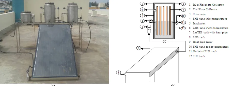
Setup Description: The details of the experimental setup are shown in Fig.1. Setup consists of a flat pate collector and LHTES tanks. This LHTES tank consist of two compartments upper is latent heat storage (LHS) and bottom is SHS. LHTES tank is of 300mm*550mm (Internal) made of stainless steel with capacity of about 36 liters, 18 liters is stored in LHS with PCM and the remaining half is stored in water in sensible form. LHTES have heat pipes embedded in the tank. Second tank is also similar to first tank in all means only except in place of heat pipe copper pipes are used. Third tank is SHS tank; both these tank are built in with the setup to test the performance of copper pipe over heat pipe and LHTES over SHTES but this is not of interest as per as this study is concern.. It houses the PCM and heat pipes and allows for heat transfer between the heat pipes inserted half inside PCM and half in water. Copper plate of 10mm thickness and 300mm diameter separates the compartment between SHS and LHS. Heat pipes 7 in number are arranged in same fashion. One pipe is placed at the centre and remaining 6 at the radial distance of 200 mm. All 6 pipes are equidistance and equiangular with the central pipe. Glass wool insulation of 50 mm thickness with density 48 kg/m3 is provided with an aluminium cladding externally. Four RTDs are provided on each LHTES tank and two on SHS tank. RTDs are located at 4 different locations in the LHTES tanks. One RTD at radial 100 mm from centre and axial 180 mm from bottom of LHS, Second RTD radial 250 mm from centre and axial 350 mm from bottom of LHS, third & fourth RTD at inlet and outlet of SHS. This arrangement is same for both LHTES. Two RTDs are provided at the inlet and outlet of third SHS tank. Care was taken while placing RTDs that it will not touch to the pipes.
(a) (b)
Fig. 1 Details of experimental setup (a) Actual photograph of experimental setup (b) Schematic diagram of experimental setup
Vol. 5, Issue 12, December 2016
Copyright to IJIRSET DOI:10.15680/IJIRSET.2016.0512056 21244
0.4 0.5 0.6 0.7 0.8 0.9 1
60 70 80 90 100 110 120 130
Q
m
a
x
(K
w
h
)
Fill Ratio (%)
Qmax
The uncertainty analysis for the experimentation was carried. Uncertainty in the experimental measurement in the HTF temperature change (from the inlet to the exit of the LHTES) was calculated using the sequential perturbation method [28], yielding uncertainties between ±6 and 10% of the measured temperature difference. To quantify the uncertainty in charging and discharging rates, reproducibility trials were conducted for both charging and discharging experiments, from which 90% confidence intervals were calculated using small-sample statistics.
Experimental Procedure: In order to test the performance of heat pipe in the LHTES with different fill ratio, during every trial before start of experimentation the setup was tested for leaks. The storage unit filled with the molten paraffin and the hot water passes through the coil till the PCM in the storage unit melted. When the complete fusion of PCM is reached, the solidification process is initiated by passing cold water into the pipe of heat exchanger. Trail experimental run was conducted and test result was validated. Experimentation was carried for charging and discharging separately and observations were recorded manually. Charging process was conducted during sunshine day and repeated for several times. Charging trial was conducted for 3 hrs continuously from 11.00 am to 2.00 pm. HTF was circulated through the Thermal energy storage (TES) tank and the solar collector unit continuously. After complete melting is achieved, further heat addition from the HTF causes the liquid PCM sensible heat storage. The charging process continues till the PCM and the HTF attain thermal equilibrium. Discharging process was conducted with covering on FPC. Using bypass a certain quantity of hot water is withdrawn from the TES tank and mixed with cold water to obtain a nominal temperature of 450C to 500C for direct use and the tank is refilled with cold water to maintain a constant amount of water in tank. This is then repeated for intervals of 10 minutes several times. Volume flow rate of 10 ltr./min. was kept constant [10]. Results were reported in terms of temperature difference to take care of difference in environmental temperature and inlet temperature of water. The temperature distributions of HTF and the PCM in the PCM tank for test specimen of different fill ratio of heat pipe. Test specimens were manufactured as per the design and tested for their dimensions.
V. EXPERIMENTAL RESULTS
Effect of Fill Ratio on Evaporator and Condenser temperature
The temperature history of storage tank with heat pipe fill ratio (80%, 90%, 100%, 110% and 120%) was recorded during charging process. Fig.3 represents the variation of evaporator and condenser temperature along with the temperature difference with time for different fill ratio in heat pipe during charging of storage tank. As can be seen, the temperature response of the condensation section is somewhat slower than that of the evaporation section. It is also observed that there exists a turning point for the response of temperature difference between the evaporation section and the condensation section, and the temperature difference appears as an exponential decrease until steady state reaches. Fig. 4 represents the maximum heat transfer through the heat pipes for different fill ratios.
Fig.3 Temperature response of evaporator and condenser 0
10 20 30 40 50 60 70 80
0 20 40 60 80 100 120 140 160 180 200
T
em
p
era
tu
re
D
if
fe
re
n
c
e
(
0C)
Time (Min.)
Te Tc
∆T
20 25 30 35 40 45 50 55 60
0 20 40 60 80 100 120 140 160 180 200
E
v
a
p
o
ra
to
r
T
em
p
era
tu
re
(
0C)
Time (Min.) 80% 90% 100% 110% 120%
This phenomenon indicates that the heat pipe experiences a dramatic start-up process. When the heat pipe is speedily heated on the evaporation section, it takes time for the working fluid to vaporize, pass through the vapor tunnel of the heat pipe, condense, reject heat to the condensation section and finally flow back to the evaporation section. The necessary time of the above processes forms a short time lag for the condensation section to react and results in a particular response of temperature difference.
As can be conceived, the conditions of the vapor tunnel or the wick structure would influence the temperature responses, since an enlarged barrier for vapor to pass through the tunnel would slow the response of the temperature at condensation section. Besides, if the capillary head of the wick structure is reduced, there would be less of a mass flux of condensate flowing back to the evaporation section and the evaporation section would be cooled at a slower rate. Conclusively speaking, the entire mentioned phenomena would reflect upon the response of the temperature difference between the evaporation and condensation sections, especially its decreasing trend after the turning point. A slower rate of decrease in temperature difference at a specific heating temperature actually represents worse internal conditions for a heat pipe.
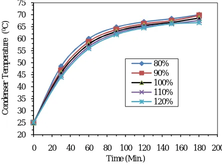
Fig. 5 Effect of fill ratio on temperature response of evaporator section Fig. 6 Effect of fill ratio on temperature response of condenser section
As shown in Fig. 5 and Fig. 6, experimental results demonstrate that the temperature response of the condensation section of a heat pipe is not influenced by the fill ratio of the working fluid, but a faster temperature response of the evaporation section is found when the fill ratio is reduced below the normal quantity. As the fill ratio is not sufficient, a greater portion of heat would be directly absorbed by the wall and wick structure of the heat pipe. Hence, a more rapid rise in temperature would result. As illustrated in Fig. 2, Qmax rises with a larger fill ratio. A larger fill ratio makes it more difficult for dry-out to occur at the evaporation section. However, a thicker film of working fluid in the wick structure also leads to greater thermal resistances between the heat pipe wall and vapor, and it would occur both in the evaporation section and the condensation section as the fill ratio increases. As a result, the effective thermal resistance of the heat pipe is increased. It is also noticed that Tmax rise with increasing fill ratio. As discussed in the previous section, when more working fluid is charged into the heat pipe, the maximum instant heat and mass flow rate of the working fluid would be enlarged and lead to a greater Tmax. On the other hand, the ability to reach uniformity of temperature would not be easily enhanced for a heat pipe with a greater fill ratio. The temperature responses are less sensitive to heating temperature due to the increase in heat capacity of both the evaporation and condensation sections.
Effect of Fill Ratio on Charging and Discharging Process of LHTES
The temperature history of storage tank with heat pipe fill ratio (80%, 90%, 100%, 110% and 120%) was recorded during charging process. Fig.5. and Fig. 6 represent the variation of LHS and SHS tank temperature with time for
20 25 30 35 40 45 50 55 60 65 70 75
0 20 40 60 80 100 120 140 160 180 200
Co
n
d
en
se
r
T
em
p
era
tu
re
(
0C)
Vol. 5, Issue 12, December 2016
Copyright to IJIRSET DOI:10.15680/IJIRSET.2016.0512056 21246
different fill ratio in heat pipe during charging and discharging of storage tank respectively.
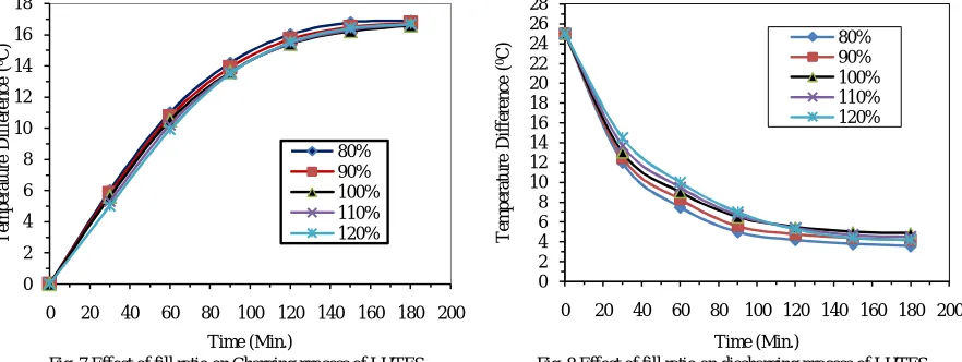
Result reported for charging and discharging during different fill ratio indicates that the cumulative energy stored in the storage tank is faster for fill ratio of 80% during charging and discharging compared to rest higher fill ratio (i,e 90% to 120%). Charging time required for preheating PCM from 350C to 500C for fill ratio of 100%, 110% and 120% is almost same and is approximately 120 min, whereas for 80% fill ratio during charging for preheating of PCM from 350C to 500C is 105 min. At the same time during discharging with 80 % fill ratio discharging time for cooling PCM in liquid sensible phase from 650C to 500C takes 40 min as compared to other higher fill ratios. As can be seen for 100% and 120% fill ratio which takes 55 min. and 60 min. respectively for both fill ratios approximately.
The time required for charging for the different fill ratio is not much affected but for discharging process the fill ratio makes sense and discharging time reduces drastically. For the specific application of the heat pipe in transferring the heat in PCM, the condenser section heat transfer rate depends on the heat transfer through heat pipe evaporator section to condenser section, convective heat transfer between the walls of condenser section and surrounding PCM properties as well the geometrical parameters of the condenser section.
Fig. 7 Effect of fill ratio on Charging process of LHTES Fig. 8 Effect of fill ratio on discharging process of LHTES
Higher the vapor temperature at the condenser will enhance the rate of heat transfer. Increasing the fill ratio beyond certain design value will leads to chocking condition and will not change the performance compared to 100% fill ratio. Decreasing the value of fill ratio will maintain higher temperature of vapor flow such that vapor flow and condensate flow will be properly balanced and dry out situation will be avoided. Due to higher resistance of PCM to flow heat the higher temperature of condenser will not change the charging time drastically but definitely certain improvement in charging time is evident due to decrease in the fill ratio. Conversely during discharging faster discharging is possible due to higher condenser temperature and low resistance of water as compared to PCM.
VI. CONCLUSION
This work presents the experimental study for optimization of heat pipe fill ratio in particular application of heat pipe embedded LHTES and found significant effect of fill ration on performance of heat pipe embedded in latent thermal energy storage. It also presented experimental performance improvement in charging and discharging due to change in fill ratio. Decrease fill ratio to the certain extent upto of 80% show the better charging and discharging in the storages tank. This will reduce the rate of heat transfer through the heat pipe Resistance to heat flow during two phase boundary create the situation of dry out to certain extent less condensation in LHTES tank. Lower value of fill ratio in this application will maintain higher value of condenser temperature and better quality heat with higher value of temperature penetrate with lower resistance in shorter time. Optimum fill ratio in heat pipe maximizes the heat transfer in Latent thermal energy storage.
0 2 4 6 8 10 12 14 16 18
0 20 40 60 80 100 120 140 160 180 200
T
em
p
era
tu
re
D
if
fe
re
n
c
e
(
0C)
Time (Min.)
80% 90% 100% 110% 120%
0 2 4 6 8 10 12 14 16 18 20 22 24 26 28
0 20 40 60 80 100 120 140 160 180 200
T
em
p
era
tu
re
D
if
fe
re
n
c
e
(
0C)
REFERENCES
[1] R.Velraj, R.V. Seeniraj, B. Hafner, C. Faber and K. Schwarzer, Heat transfer enhancement in a latent heat storage system, Journal of Solar Energy, 65 (3) (1999) 171– 180.
[2] E.M. Sparrow, E.D. Larson, J.W. Ramsey, Freezing on a finned tube for either conduction-controlled or natural-convection-controlled heat transfer, International Journal of Heat Mass Transfer, 24 (2) (1981) 273–283.
[3] F. Agyenim, P. Eames and M. Smyth, Heat transfer enhancement in medium temperature thermal energy storage system using a multitube heat transfer array, Journal of. Renewable Energy, 35 (1) (2010) 198–207.
[4] W.S. Lee, B.R. Chen, and S.L. Chen, Latent heat storage in a two-phase thermosyphon solar water heater, Journal of Solar Energy Engineering, 128 (1) (2006), 69–76.
[5] Z. Liu, Z. Wang and C. Ma, An experimental study on heat transfer characteristics of heat pipe heat exchanger with latent heat storage. Part I: charging only and discharging only modes, Energy Conversion Management, 47 (7) (2005) 944–966.
[6] H. Shabgard, T.L. Bergman, N. Sharifi and A. Faghri, High temperature latent heat thermal energy storage using heat pipes, International Journal of Heat Mass Transfer, 53 (15-16) (2010) 2979–2988.
[7] F. Tardy and Samuel M. Sami, Thermal analysis of heat pipes during thermal storage, Applied Thermal Engineering, 29 (2009) 329–333. [8] Christopher W. Robak, Theodore L. Bergman and Amir Faghri, Enhancement of latent heat energy storage using embedded heat pipes,
International Journal of Heat and Mass Transfer, 54 (2011) 3476–3484
[9] Nourouddin Sharifi, Shimin Wang, Theodore L. Bergman and Amir Faghri, Heat pipe-assisted melting of a phase change material, International Journal of Heat and Mass Transfer, 55 (2012) 3458–3469
[10] R.M. Patil and C. L. Ladekar , Experimental Investigation for Enhancement of Latent Heat Storage using Heat pipes in Comparison with Copper Pipes, International Refereed Journal of Engineering and Science, ISSN (Online) 2319-183X, (Print) 2319-1821, Volume 3, Issue 9 (September 2014), PP.44-52. (Online available at http://www.irjes.com/Papers/vol3-issue9/G394452 )
[11] S.Shandilya and C. L. Ladekar, Experimental Investigation for Enhancement of Thermal Energy Storage using Heat Pipe, International Engineering Research Journal (IERJ), Special Issue Page 1047-1057, June 2016, ISSN 2395-1621, www.ierjournal.org, (Online available at
http://www.ierjournal.org/pupload/mit/HP6-11 )
[12] Reda I. ElGhnam, Ramdan A. Abdelaziz, Mohamed H. Sakr and Hany E. Abdelrhman, An experimental study of freezing and melting of water inside spherical capsules used in thermal energy storage systems, Ain Shams Engineering Journal, (2012) 3, 33–48.
[13] Shuangfeng Wang, Jinjian Chen, Yanxin Hu and Wei Zhang, Effect of evaporation section and condensation section length on thermal performance of flat plate heat pipe, Applied Thermal Engineering, 31 (2011) 2367-2373.
[14] Ravi S. Prasher, A simplified conduction based modeling scheme for design sensitivity study of thermal solution utilizing heat pipe and vapor chamber technology, Journal of Electronic Packaging, 125 (2003) 378-385.
[15] B.K. Tan, T.N. Wong and K.T. Ooi, A study of liquid flow in a flat plate heat pipe under localized heating, International Journal of Thermal Sciences,49 (2010) 99-108.
[16] Y. Koito, K. Motomatsu, H. Imura, M. Mochizuki and Y. Saito, Fundamental investigations on heat transfer characteristics of heat sinks with a vapour chamber, in: Proceedings of the 7th International Heat Pipe Symposium, (2003), pp. 247-251.
[17] Nat Thuchayapong, Akihiro Nakano, Phrut Sakulchangsatjatai and Pradit Terdtoon, Effect of capillary pressure on performance of a heat pipe: Numerical approach with.
[18] Xiaohong Gui, Dawei Tang, Shiqiang Liang, Bin Lin and Xiugan Yuan, Influence of void ratio on thermal perfor-mance of heat pipe receiver, International Journal of Heat and Fluid Flow, 33 (2012) 109–117.
[19] C.W. Chann, E. Siqueiros, J. Ling-Chin, M. Royapoor and A.P. Roskilly, Heat utilization technologies: A critical review of heat pipes, published in Renewable and Sus-tainable Energy , 50 (2015)615–627.
[20] Te-En Tsai, Guan-Wei Wu, Chih-Chung Chang, Wen-Pin Shih and Sih-Li Chen, Dynamic test method for determin-ing the thermal performances of heat pipes, International Journal of Heat and Mass Transfer, 53 (2010) 4567–4578.
[21] Chandrakishor Ladekar, S.K.Choudhary, S.S.Khandare, A Critical Review - Optimization of Heat Pipe, International Journal of Engineering Research & Technology (IJERT), Special Issue(2016) 274-280, ISSN: 2278-0181, www.ijert.org, (Online available at
http://ems.ijert.org/conference-proceedings.php)
[22] Chandrakishor Ladekar, S.K.Choudhary, S.S.Khandare, Experimental investigation for the optimization of heat pipe performance in latent heat thermal storage, 18th International heat pipe Conference and 12th International heat pipe symposium, Jeju South Korea, 12-16 June 2016.
(under review at journal of mechanical science and technology (JMST) published by spinger)
[23] G.P. Peterson, An Introduction to Heat Pipes: Modeling, Testing and Applications, Wiley, New York, 1994. [24] A. Faghri, Heat Pipe Science and Technology, Taylor & Francis, Washington, DC, 1995.
[25] S. Murer, P. Lybaert, L. Gleton, A. Sturbois, Experimental and numerical analysis of the transient response of a miniature heat pipe, Appl. Therm. Eng. 25 (16) (2005) 2566–2577.
[26] A. Faghri, C. Harley, Transient lumped heat pipe analyses, Heat Recovery Syst. CHP 14 (4) (1994) 351–363.
[27] S.W. Churchill, H.H.S. Chu, Correlating equations for laminar and turbulent free convection from a vertical plate, Int. J. Heat Mass Transfer 18 (11) (1975) 1323–1329.