Frequency Reconfigurable Patch Antenna for
Bluetooth, WLAN and Radar Applications
Cheruku Jaya 1, Tumati Venkateswara Rao 2
P.G. Student, Department of Electronics and Communication Engineering, Sir C.R.Reddy College of Engineering,
Eluru, Andhra Pradesh, India1
Head of the Department, Department of Electronics and Communication Engineering, Sir C.R.Reddy College of
Engineering, Eluru, Andhra Pradesh,India2
ABSTRACT: This paper describes the design and simulation of a frequency reconfigurable microstrip patch antenna for Bluetooth, WLAN and Radar applications. Bluetooth and FI operates at 2.45GHz frequency, WLAN and WI-MAX operate at 5GHz band, and Marine Radar operating frequency is 7.5GHz. These three antennas are designed and simulated using Ansoft HFSS V.13 software. Rectangular patch antenna with inset feeding is used as radiating element. Rogers RT/duroid 5880 (tm) dielectric substrate with ԑr = 2.2 and thickness 1.6mm is taken. For each antenna Return loss, VSWR, Radiation Pattern was observed. These three antennas are integrated into single structure and RF-switches are used to achieve frequency reconfigurability.
KEYWORDS: Microstrip Patch Antenna, HFSS, VSWR, Reconfigurability.
I. INTRODUCTION
Ultrawideband technology was discovered by Robert A. Scholtz. Federal Communication Commission (FCC) has [1] allocated 7,500MHZ of spectrum from 3.1 to 10.6GHZ for unlicensed use of ultrawideband (UWB) communication in 2002. It is a short range radio technology compliment to existing long range technologies such as Wi-Fi, and cellular communication. It finds applications in various areas where simple hardware, low power consumption and high data rate is required such as medical, vehicular radar systems, surveillance systems, imaging systems etc [2-3].
In wireless communication system antenna is one of the important component. Antenna is an electromagnetic transducer that converts guided waves in the transmission line into free space radiated waves in transmitting mode and reverse in the receiving mode. There are several types of antennas exist, among all microstrip antennas are low profile antennas. These antennas are very useful where low cost, less weight, and high performance are required. Most common type of microstrip antenna (printed antenna) is the microstrip patch antenna or simply patch antenna. The patch can take any shape [4-6] but rectangular, circular and triangular [7-9] are most commonly used. Microstrip antennas have several advantages such as simple, inexpensive to manufacture. They can be fed by various types of feeding techniques [10-12] such as microstrip line feeding, coaxial feeding, aperture coupling, and proximity coupling. Microstrip line feed can be either inset/cut feed, edge feed and it is easy to fabricate and easy to match by controlling the inset position [13-14]. Modified feed structures for bandwidth enhancement were presented in [15-16].
UWB antenna design is a challenging task due to the interference from existing technologies such as WLAN which operates between 5.1-5.8GHZ. But they have the advantage that they can implement notch characteristic on the antenna itself. Numbers of single band notch, dual, triple band notch designs were presented in [17-19]. As the demand for antennas with switchable systems is increasing recently reconfigurable antennas have drawn much attention [20]. Reconfigurable means capable of modifying. That means they have the ability to change their operating frequency, polarization, radiation pattern and phase through the use of GaAs FET, pin diodes, RF MEMS [21-23]. Several single and dual band reconfigurable designs were proposed [24-25].
were separated by a thin dielectric substrate Roggers rt/duroid 5880 (tm) of thickness 1.6 mm and dielectric constant 2.2.
Paper is organized as follows. Section II describes Microstrip patch antenna design. Design methodology is given in Section III. Section IV presents simulation results. Finally, Section V presents conclusion.
II. RELATEDWORK
B. C. C. Chang et al. [27], proposed a reconfigurable leaky mode/patch antenna controlled by PIN diode switches. This paper represents, for the first time, a fully electronically controlled reconfigurable aperture using PIN diode switches, to realize the switching between the leaky mode/patch antenna operation. A. W. M. Lee et al. [28], proposed a reconfigurable aperture (recap) patch antenna with resonant frequencies of 18 GHz and 28 GHz for use in the wideband gap filler satellite system. Finite-element method (FEM) computations are performed and compared with experimental results. V. K. Kunda et al. [29], proposed a stacked microstrip patch antenna that can been reconfigured for operation at 2 GHz and 600 MHz. Reconfiguration is achieved by using PIN diode switches. N. Jin et al. [30], proposed a novel reconfigurable antenna with both frequency and polarization diversities. M. A. Alayesh et al. [31], proposed a reconfigurable stacked Microstrip Patch Antenna (MSA) of operating frequencies in the range of (2-5) GHz for wireless applications. A. Muscat et al. [32], proposed feed antenna that can be tuned to a frequency in the range 450 MHz to 2.2 GHz. Ya-Chi Liu et al. [33], proposed a multiband frequency reconfigurable antenna that operates at multiband from 2 GHz to 4.5 GHz. Songnan Yang et al. [34], proposed a Frequency-reconfigurable antennas for multiradio wireless platforms. Y. Tawk et al. [35], proposed a new antenna design suitable for cognitive radio communication. M. T. Ali. et al. [36], proposed a reconfigurable rectangular microstrip slot patch antenna of operating frequencies in the range of (2-6) GHz for Wireless Local Area Network (WLAN) applications. Mansoul, A. et al. [37], proposed a simple frequency reconfigurable microstrip patch antenna for wireless communication, operating at either 2.2 GHz or 2.45 GHz depending on the state of the diodes PIN switches. Ramli, N. et al. [38], presented a Frequency Reconfigurable Stacked Patch Microstrip Antenna (FRSPMA) using PIN diode switch, operating at either at 2.6 GHz or 3.5 GHz frequency. Majid, H.A. et al. [39], presented a Frequency-Reconfigurable Microstrip Patch-Slot Antenna capable of frequency switching at nine different frequency bands between 1.98 and 3.59 GHz. Tayfun Ozdemir et al.
[40], proposed a A frequency tunable antenna for 4G global roaming devices operating in the 2.3-2.7GHz band.
III.MICROSTRIPPATCHANTENNADESIGN
Patch antenna is a type of microstrip antenna and it consists of a radiating patch on one side of the dielectric substrate and ground plane on other side. Copper is used for patch and ground plane. Roggers rt/duroid 5880 (tm) is used as dielectric substrate. Dielectric constant is 2.2, thickness is 1.6mm and loss tangent is 00009. Microstrip antennas have several advantages like low profile, easy fabrication but they have narrow bandwidth and low gain. In this paper bandwidth enhancement is done by using a thick substrate with low dielectric constant. Number of feeding techniques exists for coupling power to antenna. Microstrip line feeding is simple and easy to fabricate. In this paper microstrip line inset feeding is used. Individual antennas resonating at 2.45GHz, 5.5GHz, and 7.5GHz are designed using 3D EM software- Ansoft HFSS. The integrated structure is designed using RF switches.
Reconfigurability is the capability of an antenna to change or modify its fundamental operating characteristics by means of switching or material changes. Changing the resonant frequency of an antenna is called frequency reconfigurability. This can be achieved by using switches, Variable reactive loading, Structural/ mechanical changes, Material changes. PIN diodes, FETs, Optical switches, RF-MEM switches can be used to switch between different bands. In this paper MSS40155 diodes are used to achieve reconfigurability. The values of Rs, Rp, and Cp can be obtained from the data sheet of diode.
IV.DESIGN METHODOLOGY
HFSS design models for frequencies 2.45GHz, 5.5GHz, and 7.5GHz. The values are calculated from the formulas mentioned in [4].
The dimensions for 2.45GHz antenna is presented below:
TABLE I. DIMENSIONS FOR 2.45GHZ ANTENNA
S. No
Material and dimensions
Material name Width (mm) Length (mm) Height (mm)
1. Substrate 120.83 82.2 1.6
2. Ground plane 120.83 82.2 0.05
3. Patch 40.49 48.4 0.05
4. Feed line 31.25 4.93 0.05
According to the measured values, antenna is designed in HFSS software. Designing an antenna using HFSS software is presented in [26]. Return loss, VSWR, and radiation pattern plots were presented for each individual antenna and for integrated structure. Return loss should be less than -10dB for an antenna to work efficiently, and VSWR should be less than 2.
Fig. 1 HFSS model for 2.45GHz patch antenna
Microstrip line inset feeding is used here. The air box or radiation box height must be λ/4of the frequenncy of interest,
in the direction of radiation field.
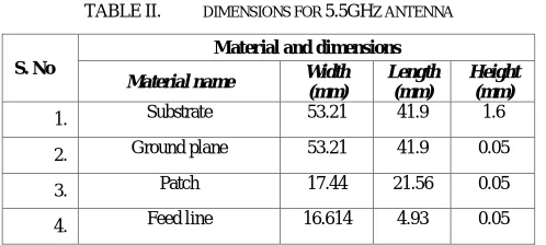
The dimensions for 5.5GHz antenna is presented below:
TABLE II. DIMENSIONS FOR 5.5GHZ ANTENNA
S. No
Material and dimensions
Material name Width (mm)
Length (mm)
Height (mm)
1. Substrate 53.21 41.9 1.6
2. Ground plane 53.21 41.9 0.05
3. Patch 17.44 21.56 0.05
HFSS design model is:
Fig. 2 HFSS model for 5.5GHz patch antenna
From the HFSS model we can see that the patch dimensions or size is decreased when frequency is increased.
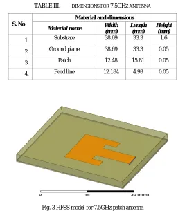
The dimensions for 7.5GHz is presented below:
TABLE III. DIMENSIONS FOR 7.5GHZ ANTENNA
S. No
Material and dimensions
Material name Width (mm)
Length (mm)
Height (mm)
1. Substrate 38.69 33.3 1.6
2. Ground plane 38.69 33.3 0.05
3. Patch 12.48 15.81 0.05
4. Feed line 12.184 4.93 0.05
HFSS model is:
Fig. 3 HFSS model for 7.5GHz patch antenna
The size of radiating patch of 7.5GHz antenna is much smaller compared to 2.45GHz and 5.5GHz antennas. From this we can say that the size of patch is inversely proportional to resonant frequency.
Fig. 4 HFSS model for 2.45/5.5/7.5GHz patch antenna Fig. 5 HFSS model for 2.45/5.5/7.5GHz patch antenna (Zoom)
3 diodes D1, D2, D3 are placed in two L- shaped slots. D1 is placed in y- direction at a distance of 4.78mm. D2 is placed in y-direction at a distance of 10.78mm and D3 is placed in x-direction at a distance of 18.78mm.
V. SIMULATION RESULTS
The designed antennas were analyzed using HFSS. Simulated results were given in this section. Return loss values for three antennas and integrated structure are
Fig. 6 Return loss plot for 2.45GHz antenna
Return loss obtained for 2.45GHz frequency is -15.2559dB. So this antenna is suitable to Bluetooth and Wi-Fi applications.
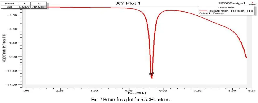
Fig. 7 Return loss plot for 5.5GHz antenna
Return loss obtained for 5.5GHz frequency is -12.5339dB. So this antenna is suitable to WLAN and Wi-Max applications.
D3
Fig. 8 Return loss plot for 7.5GHz antenna
Return loss obtained for 7.5GHz frequency is -10.6307dB. So this antenna is suitable to Radar applications.
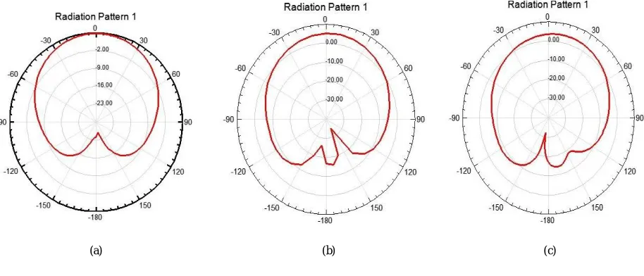
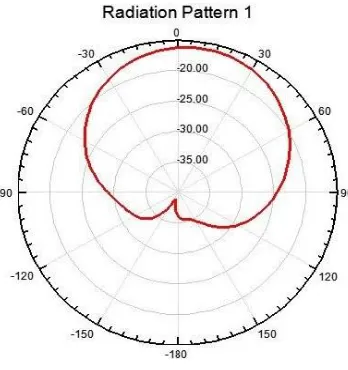
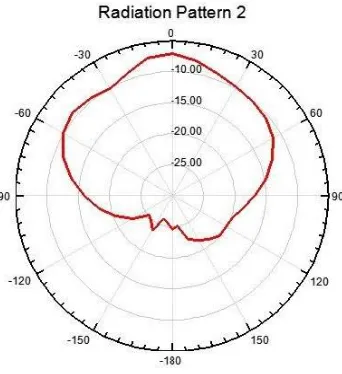
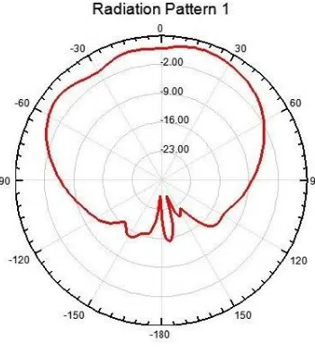
Radiations patterns for three antenna are presented below:
Fig. 9 Radiation pattern (a) for 2.45GHz patch antenna (b) for 5.5GHz patch antenna (c) for 7.5GHz patch antenna
All these patterns shows that each antenna exhibits nearly omni-directional pattern.
Simulation results for the frequency reconfigurable patch antenna for different diode conditions are given below. When diodes D1, D2 are forward biased and D3 is reverse biased, i.e. D1 D2-ON, D3-OFF, antenna operates at 2.4GHz frequency. When all three diodes are forward biased i.e. D1, D2, D3-ON, antenna operates at 5.1GHz frequency. When all three diodes are reverse biased i.e. D1, D2, D3-OFF, antenna resonates at 7.3GHz frequency. Return loss and Radiation pattern plots for 3 conditions are presented.
D1, D2- ON, D3- OFF
Figure 1. Return loss plot for 2.4GHz frequency
In this condition antenna operates at 2.4GHz with Return loss -15.0575dB.
The radiation pattern for 2.4GHz frequency is shown below:
Figure 2. Radiation pattern for 2.4GHz frequency
D1, D2, D3- ON
Figure 3. Return loss plot for 5.1GHz frequency
In this condition antenna operates at 5.1GHz with Return loss -25.2667dB.
The radiation pattern for 5.1GHz frequency is shown below:
Figure 4. Radiation pattern for 5.1GHz frequency
D1, D2, D3- OFF
Figure 5. Return loss for 7.3GHz frequency
In this condition antenna operates at 7.3GHz with Return loss -18.9124dB.
The radiation pattern for 7.3GHz frequency is shown below:
Figure 6. Radiation pattern for 7.3GHz frequency
Antenna in this condition also exhibits nearly omni-directional pattern. This integrated structure is working perfectly by switching between the three bands.
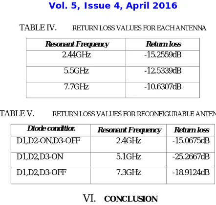
TABLE IV. RETURN LOSS VALUES FOR EACH ANTENNA
Resonant Frequency Return loss
2.44GHz -15.2559dB
5.5GHz -12.5339dB
7.7GHz -10.6307dB
TABLE V. RETURN LOSS VALUES FOR RECONFIGURABLE ANTENNA
Diode condition Resonant Frequency Return loss
D1,D2-ON,D3-OFF 2.4GHz -15.0675dB
D1,D2,D3-ON 5.1GHz -25.2667dB
D1,D2,D3-OFF 7.3GHz -18.9124dB
VI. CONCLUSION
The simulated results for 2.45, 5.5, 7.5GHz antennas show that return loss obtained is less than -10dB.i.e. 90% of signal gets absorbed and only 10% is reflected back. VSWR obtained is less than 2 for three frequencies. So the antenna works perfectly for Bluetooth, Wireless LAN and Radar applications. These three micro strip patch antennas are integrated together to form a single micro strip patch structure to operate at 3 different frequencies. 3 diodes are used to achieve switching mechanism. In each condition of diode ON or OFF antenna operates at one frequency either 2.45 GHz or 5.5 GHz or 7.5GHz, and in each case it results return loss less than -10dB and VSWR less than 2. As a future work we can implement a frequency reconfigurable MIMO (multi input multi output) antenna to reduce multipath fading.
REFERENCES
[1] Federal Communications Commission, Washington, DC, USA, “Revision of Part 15 of the commission’s rules regarding ultra-wide-band transmission systems First Report and Order FCC 02.V48,” Tech. rep., 2002.
[2] H. G. Schantz, “A brief history of UWB antennas,” IEEE Aerosp. Electron. Syst. Mag., vol. 19, no. 4, pp. 22–26, Apr. 2004. [3] H. Schantz, “The Art and Science of Ultra Wideband Antennas,” Norwood, MA: Artech House, 2005.
[4] C. A. Balanis, “Antenna theory: Analysis and Design”, 2nd ed., John Willey and & Son, Inc., 1997, pp. 722-775. [5] I. J. Bahl and P. Bhartia, “Micro-strip Antennas”, Dedham, MA;Artech House, 1980.
[6] J. R. James, “Handbook of Microstrip Antenna”, Peter Peregrinus Ltd.: London, 1989.
[7] Indrasen singh, Dr. V. S. Tripathi “Microstrip Patch Antenna and its Applications: a Survey”. int.J. Comp. Tech.Appl., Vol2 (5), 1595-1599. [8] Mailloux, R.J., et al, “microstrip antenna technology”, IEEE Trans. Antennas and Propagation, Vol. AP-29, January 1981, pp.2-24.
[9] Sumanpreet Kaur sidhu, Jagtar singh sivia “Comparison of Different Types of Microstrip Patch Antennas,” International Journal of Computer Applications (0975-8887), ICAET 2015.
[10] Marek Bugaj, Rafal Przesmycki, Leszek Nowosielski, and Kazimierz Piwowarczyk “Analysis Different Methods of Microstrip Antennas Feeding for Their Electrical Parameters”. PIERS Proceedings, Kuala Lumpur, MALAYSIA, March 27-30, 2012.
[11] K. Praveen Kumar, K. Sanjeeva Rao, T. Sumanth, N. Mohana Rao, R. Anil Kumar, Y.Harish, “Effect of Feeding Techniques on The Radiation Characteristics of Patch Antenna: Design and Analysis”, IJARCCE Vol. 2, Issue 2, February 2013.
[12] Anushi Arora, Aditya Khemchandani, Yash Rawat, Shashank Singhai, Gaurav Chaitanya “Comparative study of different Feeding Techniques for Rectangular Microstrip Patch Antenna”, International Journal Of Innovative Research In Electrical, Electronics, Instrumentation And Control Engineering Vol. 3, Issue 5, May 2015.
[13] Prof. Mahesh M. Gadag, Mr. Dundesh S. Kamshetty, Mr. Suresh L. Yogi “Design of Different Feeding Techniques of Rectangular Microstrip Antenna for 2.4GHz RFID Applications Using IE3D”, Proc. of the Intl. Conf. on Advances in Computer, Electronics and Electrical Engineering.
[14] Gurdeep Singh, Jaget Singh.” Comparative Analysis of Microstrip Patch Antenna with Different Feeding Techniques”, International Conference on Recent Advances and Future Trends in Information Technology (IRAFIT2012) Proceedings published in International Journal of Computer Applications® (IJCA).
[16] Jianjun Liu, Shunshi Zhong, and Karu P. Esselle “A Printed Elliptical Monopole Antenna with Modified Feeding Structure for Bandwidth Enhancement”, IEEE Transactions on Antennas And Propagation, VOL. 59, NO. 2, FEBRUARY 2011.
[17] Dong-Zo Kim, Wang-Ik Son, Won-Gyu Lim, Han-Lim Lee, and Jong- Won Yu, "Integrated planar monopole antenna with microstrip resonators having band-notched characteristics," IEEE Trans. Antennas Propag., vol. 58,pp. 2837-2842, September 2010.
[18] Q. X. Chu and Y. Y. Yang, “3.5/5.5 GHz dual band-notch ultra-wideband antenna,” Electron. Lett., vol. 44, no. 3, pp. 172–174, 2008. [19] J. Y. Deng, Y. Z. Yin, S. G. Zhou, and Q. Z. Liu, “Compact ultrawideband antenna with tri band notched characteristic,” Electron. Lett., vol.
44, no. 21, pp. 1231–1233, 2008.
[20] Sriram Kumar, Harshitha Goli, Priya Baskaran and P.P.Angela, “Novel Reconfigurable Microstrip Antenna”, 2008 IEEE Region 10 Colloquium and the Third International Conference on Industrial and Information System, Kharagpur, India, Dec 8-10, 2008.
[21] Jerzy Guterman, Antonio A. Moreira, Custodio Peixeiro and Yahya Rahmat-Samii, “Reconfigurable E-shaped Patch Antennas”, Antenna Technology 2009, iWAT 2009, Santa Monica, CA, 2-4 March, 2009.
[22] P. Panaïa, C. Luxey, G. Jacquemod, R. Staraj, L. Petit, and L. Dussopt, “Multistandard Reconfigurable PIFA Antenna”, Microwave and Optical Technology Letters, vol. 48, no. 10, pp. 1975-1977, July 2006.
[23] C. R. Medeiros, J. R. Costa, and C. A. Fernandes, “MEMS Reconfigurable Stacked Antenna for WLAN Applications”, Proc IEEE AP-S/URSI International Symp., San Diego, USA, July 2008.
[24] Jegan.G, Vimala Juliet A, Himanshu singhvi, “A Novel design approach of reconfigurable patch antenna for wireless application” Applied Mechanics and Materials Vols.336-338, 2013, pp: 1935-1938
[25] Mr.VivekKapur, Mrs. NilimaBodhaye, Mrs. DevashreeMarotkar, Mr.ShrishMarotkar, “Study of Reconfigurable Multiband Micro strip patch antenna for wireless communication” IJIREEICE,Vol. 1,Issue 5,August 2013.
[26] Ansoft Corporation, user’s guide – High Frequency Structure Simulator (HFSS), USA, REV1.0, 21 June 2005.
[27] B. C. C. Chang ; Dept. of Electr. Eng., California Univ., Los Angeles, CA, USA ; Y. Qian ; T. Itoh, “A reconfigurable leaky mode/patch antenna controlled by PIN diode switches”, Antennas and Propagation Society International Symposium, 1999. IEEE , Year: 1999, Volume: 4 [28] A. W. M. Lee ; Dept. of Electr. Eng., California Univ., Los Angeles, CA, USA ; S. K. Kagan ; M. Wong ; R. S. Singh, “Measurement and
FEM modeling of a reconfigurable-patch antenna for use in the wideband gap filler satellite system”, Antennas and Propagation Society International Symposium, 2003. IEEE (Volume:1 )
[29] V. K. Kunda ; Dept. of Electr. Eng., South Carolina Univ., Columbia, SC, USA ; M. Ali, “Reconfigurable stacked patch antenna for satellite and terrestrial applications”, IEEE Topical Conference on Wireless Communication Technology, 2003.
[30] N. Jin ; Dept. of Electr. Eng., Univ. of California, Los Angeles, CA ; Fan Yang ; Y. Rahmat-Samii, ”A novel patch antenna with switchable slot (PASS): dual-frequency operation with reversed circular polarizations”, IEEE Transactions on Antennas and Propagation (Volume:54 , Issue: 3 ),2006
[31] M. A. Alayesh ; ECE Dept., Univ. of New Mexico, Albuquerque, NM ; C. G. Christodoulou ; M. Joler ; S. E. Barbin, “Reconfigurable multi-band stacked Microstrip Patch Antenna for wireless applications”, Antennas and Propagation Conference, 2008. LAPC 2008.
[32] A. Muscat ; J. A. Zammit, ” Reconfigurable antenna structure for a wideband cognitive radio”, IET Seminar on Cognitive Radio and Software Defined Radios: Technologies and Techniques 2008
[33] Ya-Chi Liu ; Dept. of Electr. & Comput. Eng., Texas A&M Univ., College Station, TX, USA, “Multiband frequency reconfigurable antenna by changing the microstrip connecting element position”, Kai Chang Antennas and Propagation Society International Symposium, 2009. APSURSI '09. IEEE
[34] Songnan Yang ; Univ. of Tennessee-Knoxville/Intel Corp., Santa Clara, CA ; Chunna Zhang ; Helen K. Pan ; Aly E. Fathy, “Frequency-reconfigurable antennas for multiradio wireless platforms”, IEEE Microwave Magazine (Volume:10 , Issue: 1 ),2009
[35] Y. Tawk ; Electr. & Comput. Eng. Dept., Univ. of New Mexico, Albuquerque, NM, USA ; C. G. Christodoulou, “A New Reconfigurable Antenna Design for Cognitive Radio”, IEEE Antennas and Wireless Propagation Letters (Volume:8 ),2009
[36] M. T. Ali ; Fac. of Electr. Eng. (FKE), Univ. Teknol. Mara (UiTM), Shah Alam, Malaysia ; N. Ramli ; M. K. M. Salleh ; M. N. Md. Tan, “A design of reconfigurable rectangular microstrip slot patch antennas”, IEEE International Conference on system Engineering and Technology (ICSET), 2011
[37] Mansoul, A.; Kimouche, H., ” A simple frequency reconfigurable microstrip patch antenna for wireless communication”, 8th International Workshop on Systems, Signal Processing and their Applications (WoSSPA), 2013
[38] Ramli, N.; Ali, M.T.; Tan, M.N.M.; Yusof, A.L., “A Frequency Reconfigurable Stacked Patch Microstrip Antenna (FRSPMA) using PIN diode switch”, 10th International Conference on Electrical Engineering/Electronics, Computer, Telecommunications and Information Technology (ECTI-CON), 2013
[39] Majid, H.A.; Abdul Rahim, M.K.; Hamid, M.R.; Murad, N.A.; Ismail, M.F., “Frequency-Reconfigurable Microstrip Patch-Slot Antenna”, Antennas and Wireless Propagation Letters, IEEE, 2013