ISSN(Online) : 2319-8753 ISSN (Print) : 2347-6710
International Journal of Innovative Research in Science,
Engineering and Technology
(An ISO 3297: 2007 Certified Organization)
Vol. 5, Issue 3, March 2016
Speed Control and Protection of Three Phase
BLDC Motor with Hall Effect Sensor Using
Neuro Fuzzy Logic Controller
K.Surendhirababu1, K.Barwin2
Asst. Prof, Dept of EEE, SRM University, Ramapuram, Chennai, India 1
PG Scholar, Dept of EEE, SRM University, Ramapuram, Chennai, India 2
ABSTRACT: To implement the digital control of three phase BLDC motor. To design a neuro fuzzy logic control for speed control of BLDC motor. To make the BLDC to rotate in the constant speed To improve the system efficiency by sensing the internal hall signals of the BLDC motor The BLDC motor has some advantages compare to others type of motors. However, the nonlinearity of this motor drive characteristics cause it is difficult to handle using conventional proportional-integral-differential (PID) controller. In order to overcome this main problem, Fuzzy Logic controller with a Gaussian membership function is developed. The mathematical model of BLDC motor is derived. The controller is designed to tracks variations of speed references and stabilizes the output speed during load variations. The effectiveness of the proposed method is verified by develop simulation model in Matlab Simulink software. The simulation results show that the proposed Neuro Fuzzy Logic controller (FLC) produce significant improvement control performance compare to the PID controller for both condition controlling speed reference variations and load disturbance variations.
KEYWORDS - BLDC, Neuro Fuzzy logic controller, PWM and virtual motor, Angular displacement estimation,
brushless permanent-magnet (PM) motor, Hall-effect sensor.
I. INTRODUCTION
Nowadays, Brushless Direct Current (BLDC) motors are one of the motor types rapidly gaining popularity [1]. As the name implies, their only drawback is that they need a commutator and brushes which are subject to wear and require maintenance. When the functions of commutator and brushes were implemented by solid-state switches, maintenance-free motors were realized. BLDC motors have many advantages over brushed DC motors and induction motors which is better speed versus torque characteristics, high dynamic response, high efficiency, long operating life, noiseless operation and higher speed ranges.
Direct Current (DC) motor was chosen for the speed control applications due to the control simplicity on the intrinsic decoupling between the flux and the torque. As the name implies, there are physical limitations to speed and life time because of brush wear. However, BLDC have been produced to overcome this problem. Since there are no carbon brushes to wear out, a BLDC motor can provide significantly greater life being now only limited by bearing wear. This advantage make BLDC motor becomes popular in the industry but this motor is a non-linear system hence, need more complex speed controller than the DC motor. By this reason, the Gaussian Fuzzy Logic controller will be developed to improve the performance of variable speed for BLDC motor since the system of this motor is non-linear system.
ISSN(Online) : 2319-8753 ISSN (Print) : 2347-6710
International Journal of Innovative Research in Science,
Engineering and Technology
(An ISO 3297: 2007 Certified Organization)
Vol. 5, Issue 3, March 2016
and control method have been developed to improve the performance of BLDC motor drives [3]. Based on previous studies in linear system model, controller parameters of proportional integral derivative (PID) controller are easy to determine and resulting good control performances. However, for nonlinear system model application such as BLDC motor drive, control performance of the PID controller becomes poor and difficult to determine the controller parameters. So that, Fuzzy Logic Control (FLC) will be used in order to improve the control performance. In this project, a complete simulation model with FLC method for BLDC motor drive is proposed using Matlab/Simulink.
Several investigations on BLDC motor are reported. In 2003, Padmaraja Yedamale [23], concluded that BLDC motors have advantages over brushed DC motors and induction motors. In 2009, Bhim Singh [7] did an exhaustive overview of PMBLDCM drives. In 2010, A. Ahfock and D. Gambetta [1] presented a paper about sensorless commutation of BLDC motor by equal inductance method. In 2006, Dae-Kyong Kim, Kwang-Woon Lee, and Byung-Il Kwon [10] proposed a torque ripple reduction method for a position sensorless BLDC motor drive. In 2011, Dawid Makiela [11] examined sensorless high-speed PM BLDC motor control methods for a particular target speed. In paper [24], [29], the speed control of position sensorless brushless DC motor is discussed. In 2009, K. Wang et al [18] studied the design of high-speed brushless DC motors equipped with surface-mounted magnets, for sensorless operation based on the third harmonic back-EMF. In 2010, A. Rahideh et al [4] presented a method for the optimal design of a slotless PMBLDC motor with surface mounted magnets using a genetic algorithm. Intelligence control like generic control has paved way for increased control and accuracy. In 2002, Bhim Singh and Sanjeev singh [6] presented a new speed control strategy of a PMBLDC motor drive. In 2011, Cassio Luciano et al presented a paper [9] on speed control for BLDC compressor using a repetitive plug-in control with variable sampling period. In paper [2] and [13], torque controller system for a BLDC motor is analysed. Bogdan Alecsa and Alexandru Onea [8] presented a paper to implement a digital BLDC motor speed controller inside an FPGA device. In 2007, Eric Monmasson and Marcian N. Cirstea [12] presented a paper on the contributions of FPGAs to the control of industrial systems. In 2010, Wang Xing-gui and Liu Qi [25] suggested a robust position control of the PMBLDCM. In 2011, Hao Chen, Song Sun, Dionysios C. Aliprantis, and Joseph Zambreno [14] presented the FPGA implementation of an induction machine dynamic simulation, using numerical integration algorithm. In 1999, Z. M. Zhao, S. Meng and X N.Yue [30] developed and implemented a virtual system integrating software with hardware in loop and implemented for motor drive applications. In 2012, Jiancheng Fang, Haitao Li and Bangcheng Han [15] proposed a new PWM current control method. In 2006, Jianwen Shao [16] presented the improved direct back-EMF-sensing scheme that eliminates duty-cycle limitation by adding the option of sensing the back EMF during the high-side-switch PWM on time. In 2006, Maurício Beltrão et al [20] presented a method to generate PWM signals for control of four-switch three-phase inverters. In 2004, Yen-Shin Lai, Fu-San Shyu, and Yung-Hsin Chang [27] presented a new PWM technique for brushless dc motor drives fed by MOSFET inverter, which significantly reduces the conduction losses and especially becomes very promising for small power applications. In 2010, A Albert Rajan et al [3] presented an idea to replace the conventional constant frequency digital PWM control method for speed variation in BLDC by variable frequency and variable duty ratio fuzzy logic method.
II. BRUSHLESS DC MOTOR
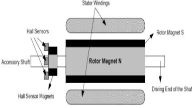
BLDC motors have electronic commutator, instead of brushes, thus they have higher efficiency, long operating life, rugged construction and noiseless operation. BLDC motor implements the basic principle of conventional DC motors except that the stator has three phase windings whereas the rotor has pole magnets. The hall sensors embedded in the motor detects the rotor position. The decoder decodes the position of the rotor and produces gate pulses to trigger the six-switch inverter to produce AC voltage that energizes the stator windings to produce current.
ISSN(Online) : 2319-8753 ISSN (Print) : 2347-6710
International Journal of Innovative Research in Science,
Engineering and Technology
(An ISO 3297: 2007 Certified Organization)
Vol. 5, Issue 3, March 2016
moved by means of actual brushes in order to move the rotor. With a BLDC motor, electrical current powers a permanent magnet that causes the motor to move, so no physical commutator is necessary. A BLDC motor is highly reliable since it does not have any brushes to wear out and replace.
BLDC motors are a type of synchronous motor. This means the magnetic field generated by the stator and rotor rotate at the same frequency. BLDC motor does not operate directly off a DC voltage source. It consists of a rotor with permanent magnets, a stator with windings and commutation that is performed electronically. Normally three Hall sensors are used to detect the rotor position and commutation is performed based on Hall sensor inputs. There are two types of stator windings variants which are trapezoidal and sinusoidal motors.
The stator of a BLDC motor consists of stacked steel laminations with windings placed in the slots that are axially cut along the inner periphery. Windings in a stator can be arranged in two patterns which is a star pattern (Y) or delta pattern (∆). Most BLDC motors have three stator windings connected in star v connection. The winding formed when each of these winding are constructed with numerous coils interconnected together. The stator windings construct into two types which is trapezoidal and sinusoidal motors. The rotor of a typical BLDC motor is made out of permanent magnets. Depending upon the application requirements, the number of poles in the rotor may vary. Increasing the number of poles does give better torque but at the cost of reducing the maximum possible speed. Another rotor parameter that impacts the maximum
torque is the material used for the construction of permanent magnet; the higher the flux density of the material, the higher the torque.
Hall sensors work on the hall-effect principle that when a current-carrying conductor is exposed to the magnetic field, charge carriers experience a force based on the voltage developed across the two sides of the conductor. If the direction of the magnetic field is reversed, the voltage developed will reverse as well. For Hall-effect sensors used in BLDC motors, whenever rotor magnetic poles North (N) or South (S) pass near the hall sensor, they generate a HIGH or LOW level signal, which can be used to determine the position of the shaft. Most BLDC motor consists of three Hall Effect sensors and the combination of this sensor will produce the exact sequence of commutation. There are two output versions by referring the physical position of the Hall sensors either at 60˚ or 120˚ phase shift to each other.
Fig. 1 BLDC motor cross section
Three windings on each commutation have different function. First windings will energized to positive power (current inflow into the winding), the second winding for negative (current out flow the winding) and the last winding is in a non-energized condition. The interaction between the permanent magnet and magnetic field generated by the stator coils will produce the torque. Basically, the peak torque occurs when these two fields are at 90˚ to each other and
falls off as the field move together. In order to keep the motor running, the magnetic field produced by the winding should shift position as the rotor moves to catch up with the stator field.
ISSN(Online) : 2319-8753 ISSN (Print) : 2347-6710
International Journal of Innovative Research in Science,
Engineering and Technology
(An ISO 3297: 2007 Certified Organization)
Vol. 5, Issue 3, March 2016
for speed range up to the rated speed. Meanwhile it capable to run up to the maximum speed which is 150% of the rated speed but the torque starts dropping during this situation.
Every 60 electrical degrees of rotation, one of the Hall sensors changes the state. Given this, it takes six steps to complete an electrical cycle. In synchronous, with every 60 electrical degrees, the phase current switching should be updated. However, one electrical cycle may not correspond to a complete mechanical revolution of the rotor. The number of electrical cycles to be repeated to complete a mechanical rotation is determined by the rotor pole pairs. For each rotor pole pairs, one electrical cycle is completed. So, the number of electrical cycles equals the rotor pole pairs.
III. NEURO FUZZY LOGIC CONTROLLER
We consider a multi-input, single-output dynamic system whose states at any instant can be defined by “n” variables X1, X2,...,Xn. The control action that derives the system to a desired state can be described by a well known concept of “if-then” rules, where input variables are first transformed into their respective linguistic variables, also called fuzzification. Then, conjunction of these rules, called inferencing process, determines the linguistic value for the output. This linguistic value of the output also called fuzzified output is then converted to a crisp value by using defuzzification scheme. All rules in this architecture are evaluated in parallel to generate the final output fuzzy set, which is then defuzzified to get the crisp output value. The conjunction of fuzzified inputs is usually done by either min or product operation (we use product operation) and for generating the output max or sum operation is generally used. For
defuzzification, we have used simplified reasoning method, also known as modified center of area method. For simplicity, triangular fuzzy sets will be used for both input and output. The whole working
and analysis of fuzzy controller is dependent on the following constraints on fuzzification, defuzzification and the knowledge base of an FLC, which give a linear approximation of most FLC implementations.
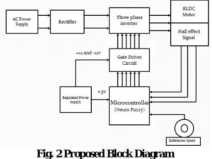
Fig. 2 Proposed Block Diagram
CONSTRAINT 1: The fuzzification process uses the triangular membership function.
CONSTRAINT 2: The width of a fuzzy set extends to the peak value of each adjacent fuzzy set and vice versa. The sum of the membership values over the interval between two adjacent sets will be one. Therefore, the sum of all membership values over the universe of discourse at any instant for a control variable will always be equal to one. This constraint is commonly referred to as fuzzy partitioning.
ISSN(Online) : 2319-8753 ISSN (Print) : 2347-6710
International Journal of Innovative Research in Science,
Engineering and Technology
(An ISO 3297: 2007 Certified Organization)
Vol. 5, Issue 3, March 2016
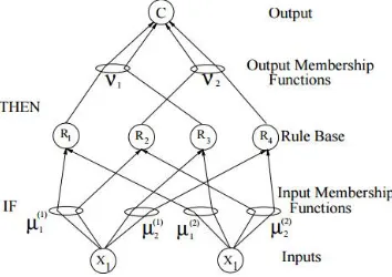
Fig. 3 Architecture of four rule fuzzy controller from neural networks point of view
A PFLC, which is represented by the above “if - then'' rules, can be easily implemented in the form of a neural network . There is one input node, known as an error node. The input node feeds to the intermediate or hidden layer of rules, through weighted connections. These weights are essentially the definitions of linguistic variables or the fuzzy sets. At these shared weights, the input error is converted into linguistic variables and fed to the rule modules or rule layer. Each rule module processes the information available to its input in parallel. Rule module takes the input from input layer (error) conditioned by the fuzzy weights (fuzzification) and finds the conjunction of the inputs. The output of rule module is then fed to the output layer through weighted connections. The weights are definitions of output fuzzy sets and at the output defuzzification is performed which is chosen to be the “modified center of gravity'' approach.
IV. RESULTS
Fig. 4 Proposed Simulink Diagram
ISSN(Online) : 2319-8753 ISSN (Print) : 2347-6710
International Journal of Innovative Research in Science,
Engineering and Technology
(An ISO 3297: 2007 Certified Organization)
Vol. 5, Issue 3, March 2016
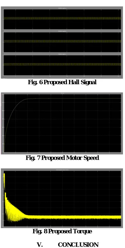
Fig. 6 Proposed Hall Signal
Fig. 7 Proposed Motor Speed
Fig. 8 Proposed Torque
V. CONCLUSION
In this paper, the simulation of the drive is performed Neuro fuzzy logic controller using Matlab/Simulink. The speed control is achieved at various load torque conditions with constant speed reference and at constant load with varying speed references. From the speed curve, it is seen that there is a peak overshoot in the case of fuzzy control, it is smooth. The Neuro fuzzy controller responds faster and smoother to reference speed changes compared to the PI controller. Fuzzy model proved to be more flexible, while developing a speed controller for constant speed reference with changing load torque, whereas, Neuro fuzzy model proved to provide more accuracy for changing speed reference with constant load torque conditions The microcontroller based PI controller implementation is successfully tested with virtual motor.
REFERENCES
[1] A. Ahfock and D. Gambetta,”Sensorless commutation of printed circuit brushless direct current motors,” published in IET Electric Power Applications received on 4th June 2009.
ISSN(Online) : 2319-8753 ISSN (Print) : 2347-6710
International Journal of Innovative Research in Science,
Engineering and Technology
(An ISO 3297: 2007 Certified Organization)
Vol. 5, Issue 3, March 2016
[3] A Albert Rajan, R. Daniel Raj and Dr. S. Vasantharathna,” Fuzzy Based Reconfigurable Controller for BLDC Motor,” second International conference on Computing, Communication and Networking Technologies 2010.
[4] A. Rahideh, T.Korakianitis , P.Ruiz, T.Keeble and M.T.Rothman ,”Optimal brushless DC motor design using genetic algorithms ,” Journal of Magnetism and Magnetic Materials 322 (2010)
[5] Baharuddin Ismail and Tan Chee Siong,”Study of fuzzy and PI controller for permanent magnet BLDC motor drive,” The 4th International Power
Engineering and Optimization Conf. (PEOCO2010), Shah Alam, Selangor, MALAYSIA: 23-24 June 2010.
[6] Bhim Singh and Sanjeev Singh,” A Voltage Controlled Adjustable Speed PMBLDCM Drive using A Single-Stage PFC Half-Bridge Converter,” Electrical Engineering Department, Indian Institute of Technology Delhi, New Delhi -110016, India.
[7] Bhim Singh,”Recent advances in permanent magnet Bldc motor,” vol 22, part6, pp 837-853,2010.
[8] Bogdan Alecsa and Alexandru Onea,” An FPGA Implementation of a Brushless DC Motor Speed Controller,” 2010 IEEE 16th International
Symposium for Design and Technology in Electronic Packaging (SIITME).
[9] Cassio Luciano Baratieri and Humberto Pinheiro ,”Speed Control for BLDCM Driver Using Repetitive Control,” 2011 IEEE International Electric Machines and Drives Conference(IEMDC).
[10] Dae-Kyong Kim, Kwang-Woon Lee, and Byung-Il Kwon ,”Commutation Torque Ripple Reduction in a Position Sensorless Brushless DC Motor Drive,” IEEE TRANSACTIONS ON POWER ELECTRONICS, VOL. 21, NO. 6, NOVEMBER 2006
[11] Dawid Makiela“Sensorless Control of High-Speed PM BLDC Motor,” Silesian University of Technology, Department of Power Electronics, Electrical Drives and Robotics,2011.
[12] Eric Monmasson, and Marcian N. Cirstea“FPGA Design Methodology for Industrial Control Systems,” IEEE TRANSACTIONS ON INDUSTRIAL ELECTRONICS, VOL. 54, NO. 4, AUGUST 2007.
[13] H. Jang, J.H. Yeom and M.G. Kim,” Determination of torque–speed–current characteristics of a brushless DC motor by utilizing back-EMF of non-energized phase”, Journal of Magnetism and Magnetic Materials 310 (2007).
[14] Chen, Song Sun, Dionysios C. Aliprantis, and Joseph Zambreno ,”Dynamic Simulation of Electric Machines on FPGA Boards” Department of Electrical and Computer Engineering Iowa State University, Ames, IA 50011