1
Article
2
A Novel Method for 3D Absolute Localization and
3
Orientation of a Stair Cleaning Robot using Staircase
4
Geometry and Onboard Sensors
5
Ilyas Muhammad1,2, Vinu Sivanantham1, Manojkumar Devarassu1, Balakrishnan Ramalingam1,
6
Mohan Rajesh Elara1,*
7
1 Engineering Product Development Pillar, Singapore University of Technology and Design (SUTD),
8
Singapore 487372.
9
2 Department of Electrical Engineering, UET Lahore 54890, NWL Campus, Pakistan.
10
*Correspondence: [email protected]; Tel.: +65-9023-4275
11
12
13
Abstract:
The sTetro is a stair cleaning robot which can climb the staircase with its shapeshifting14
capabilities. As this robot is intended to traverse multi-floor environment autonomously, hence its
15
localization/positioning information is an essential component of the overall system. Usually, the
16
indoor mobile robots rely on some external system for localization information, e.g., WiFi, UWB,
17
vision, RFID signals, or indoor Global Positioning System (GPS). This requires the installation of
18
additional hardware and/or modification of the working environment for precise positioning
19
information of the mobile platform. As the dimensions of the staircase are known a priori, this
20
knowledge can be used to localize the sTetro robot on the stairs. In this article, the geometry of the
21
staircase has been exploited to localize the robot in 3D space with measurements from the onboard
22
time-of-flight (ToF) range sensors only. The heading angle of the robot is also estimated with two ToF
23
sensors installed in front of the sTetro robot. Results achieved by conducting experiments on real
24
robot prove the efficacy of the proposed approach.
25
26
Keywords: Indoor environment; 3D localization; staircase geometry; robotics; time-of-flight sensors.
27
28
1. Introduction
29
Any mobile robotic system comprises of many systems and subsystems for its proper operation,
30
however, some significant modules are essential for the autonomous operation of the mobile
31
platforms [1], [2]: control system module, path planner module and localization/positioning module. Among
32
them, the localization module is responsible for providing correct information of position and
33
orientation [3]. The other significant modules of the robotic system mainly depend on the accuracy
34
of the localization system.
35
Mainly there are two types of localization/positioning systems, 1) Absolute positioning system,
36
2) Incremental/relative positioning system [4],[5]. In absolute positioning system the position
37
information is available with respect to some global reference coordinate frame and usually does not
38
combined with other sensors/systems, e.g., inertial measurement unit, camera, Lidar, vision sensors
45
etc. [10], [11]. However, for indoor mobile robotic platforms, GPS is not readily available, hence
46
other forms of absolute positioning are employed, e.g. WiFi signals are used to estimate absolute
47
position ofmobile devices[12]. Similarly, other beacons-based absolute positioning systems are
48
employed to get the absolute position of a mobile platform in an indoor environment [3], [6],
49
[13]–[18]. However, this requires some additional hardware modifications in the working
50
environment, which adds additional cost and/or complexity of the overall system.
51
In this work, we present a novel yet very simple technique to estimate the 3D absolute
52
localization information of an indoor mobile robot, called sTetro, developed at RoAR Laboratory,
53
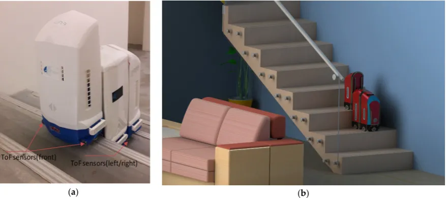
SUTD [19]. Sensor installation and typical working environment of this robot is shown in Figure 1.
54
As the working environment of the sTetro robot is a staircase which has fixed and known dimensions
55
of each step’s tread and riser. This a prior knowledge of staircase geometry is exploited for
56
localization information estimation along with onboard sensors measurements only. Some of the
57
terminologies related to staircase geometry are given in Figure 2. Two time of flight (ToF) sensors are
58
installed on the left and right side of the robot. The distance measurements obtained from two ToF
59
sensors are used to calculate y-axis position on the tread. As the dimensions of stair’s tread and riser
60
are known, the x-axis and z-axis position is derived from the known geometry of the staircase as
61
robot climbs on the stair steps. Two ToF sensors are also installed in front of the robot facing front
62
riser. The range/distance measurements of these two ToF sensors are used to calculate the heading
63
angle of the sTetro when it traverses left and right on the tread of a step.
64
The remaining article is organized as follows. In section 2, a brief introduction of the sTetro
65
robot is given. We present 3D localization calculation method of the sTetro in section 3, and in section
66
4 the orientation estimation scheme is presented. Section 5 gives the experimental setup and results
67
discussion. Section 6 concludes the work and proposes some future directions.
68
69
2. Introduction of sTetro: A Staircase Cleaning Robot
70
The sTetro, a staircase cleaning robot, is a reconfigurable robot which uses a vertical conveyor
71
belt mechanism to climb the staircase. The working principle of sTetro is borrowed from the Tetris
72
game [20]. The sTetro robot's body consists of three cuboids connected with two sliders attached to
73
each side of the central cuboid. The hollow space inside each parallelepiped block encloses the
74
electronic units, vacuum/suction tools and sweeping mechanism (planned). The blocks have a
75
modular design, which allows reusing many pieces in the system. A GUI has been designed which
76
allows the user to control the robot’s motion, as desired. The reconfiguration mechanism allows the
77
sTetro robot to efficiently traverse both the floor and stairs, which is almost impossible in presently
78
available home cleaning robots in the market. The newer version of the sTetro has capabilities to
autonomously navigation on the staircase without user intervention. Pictures of old and newer
80
versions of sTetro robot are shown in Figure 1 bellow.
81
82
(a) (b)
Figure 1. (a) sTetro (new ver.) robot with sensors installed for this work, (b) sTetro (old ver.) robot’s
83
typical working environment: A staircase.
84
85
3. Absolute 3D Position of sTetro
86
In order to get absolute position information on all three axes (i.e. x-axis, y-axis, and z-axis),
87
only the y-axis position is measured by ToF sensors in this work. The position along other two axes is
88
calculated from the known geometry of the staircase. For instance, the width of a tread of stair step
89
and height of riser is fixed on any staircase and can be measured manually. When the robot climbs
90
the staircase, the distance traveled along x-axis and z-axis can be calculated if the step number is
91
known on a staircase. The 3D absolute position of the sTetro is calculated as in Equation (1).
92
120cm
2
; 1, 2,..., .
; <
; l
i l i
i l i
j i
j t
x t step
z r step i N
d if sensor output
y
W d otherwise
= × −
= × =
= −
(1)
93
Where
t
landr
lare lengths of tread and riser of a staircase,x
iandz
iare position along the x-axis94
and z-axis respectively,
d
jis ToF sensor measurement along the y-axis,W
is the width of staircase95
and
i
is the step number counter.Figure 2. Staircase geometry to calculate 3D position and orientation of sTetro robot.
99
100
101
To calculate the robot position along the y-axis, the measurements from distance sensors
102
installed at both sides of the robot are used. The reason that two ToF sensors are installed on left and
103
right side of sTetro is that these sensors have limited raging capability (120cm), so when the robot
104
is on extreme left or right side of the stair, the distance measurements of the sensor become
105
unreliable. In this case, the measurements of the sensor on the other side of the robot are used to
106
calculate position on the stair along y-axis. The complete pseudo-code for 3D position and
107
orientation (heading) estimation is given in Algorithm I below.
Algorithm I: Pseudo code for 3D localization and heading estimation of sTetro.
0 0 0 0
// 120
: x 0, , 0
1 //
( )
( ) 0.5 ( )
( < )
k l l
k l
k k
lim itM ax cm
y Y z
i step num ber
i N
x t i t
z r i
sensor output limitM ax
y d = ← ← ← = ≤ ← × − ← × ← Initializ
L oop : w hile
if
1 2 1
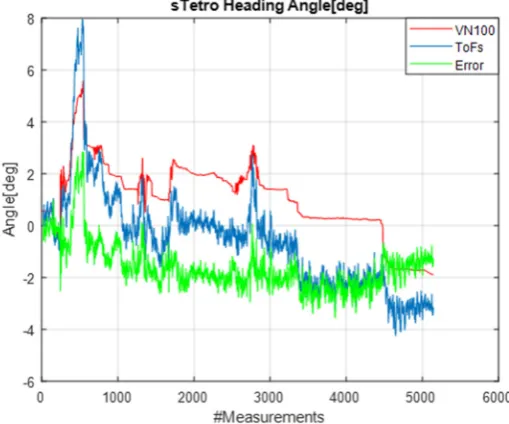
tan ( 0) () ( 0) () () k k k k k
y W d
d d D rotateC W rotateC CW i readStep θ θ θ − ← − − ← > < ← else if if end loop
124
125
4. Orientation Calculation and Misalignment Correction
126
As the working environment of sTetro is staircase which has almost flat treads, hence the roll
127
and pitch angle of sTetro are nearly zero in normal operation of the robot. Only heading angle
128
(rotation about the z-axis) may change while traveling left/right on the treads. Two ToF sensors are
129
installed at the front end of the sTetro robot to keep track of the heading angle. The role of these two
130
sensors is to calculate the heading angle of the robot from the range measurements of the two
131
sensors. Time of flight sensors give direct distance measurements with respect to the front riser of
132
the step. The heading angle is calculated as follows in Equation (2),
133
134
1 2 1
tan k d d D
θ
= −
−
(2)135
whered1,d2are distance measurements from ToF sensors installed in front of the robot, andDis the
136
width of the sTetro robot. If both distances are nearly equal, it leads to the conclusion that the robot is
137
aligned with the front riser and heading angle is almost zero. If two ranges are not equal, a positive
138
or negative heading angle indicates the misalignment of the robot with the front riser. Then the
139
control system sends signals to actuators to turn sTetro clock-wise or anti-clock-wise in order to keep
140
it aligned with the front riser for smooth motion. Heading angle estimation and correction scheme in
141
this work is illustrated in Figure 3 below.
(a)
(b)
Figure 3. (a) Heading angle calculation from ToF sensor measurements, (b) Depiction of misalignment of sTetro
145
on stair tread.
146
147
5. Experimental Setup and Results discussion
148
149
The sTetro robot’s design and working principle are described in full detail in our previous
150
work[19]. The sTetro robot is equipped with four additional ToF sensors for experiments conducted
151
in this work. The distance sensor (VL53L0X) measures absolute range up to 2 meters [21]. An
152
experimental setup for this work is shown in Figure4.
153
154
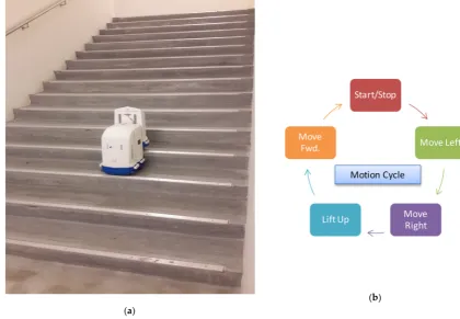
(a)
(b)
Figure 4. Experimental setup, (a) sTetro robot traversing the staircase, (b) One motion cycle of sTetro.
155
The sTetro robot is driven to traverse staircase as shown in Figure 4(a). The motion cycle for
157
covering one stair step is given in Figure 4(b). Left and right wall strings restrict the motion of the
158
robot. Two ToF sensors are installed on the left and right side of the central block and 2×ToF sensors
159
are fitted in front of the first block of sTetro. The robot is started to move on the tread of the first step
160
from right to left. After reaching extreme left of the tread, the left bumper touches the left wall string,
161
and robot starts to move towards right on the tread. When the robot reaches the rightmost side, the
162
right bumper touches the right wall string, and the robot starts to move towards left. After reaching
163
midway on the tread, it stops and lifts central and last block to climb up to the next level. The
164
counter in the software is incremented each time the robot climbs to the next step, thus counting the
165
number of steps. This motion pattern repeats on the second step and so on, as before on the first step.
166
During left/right motion, all four sensors measure the distances (d1d4) which are used to calculate
167
y-position and heading angle of the robot.
168
169
5.1. Heading Angle: Static test
170
171
In the first test, the two front sensor’s range data (d d3, 4) is used to calculate the heading angle
172
of the robot. To assess the accuracy of the proposed method, a static test is performed first. The robot
173
facing the front riser of the stair is rotated from +45° to -45° in continues rotation. Straight lines are
174
marked with the help of angle protector at designated angles: 0°, -45°, +45°. Starting from facing the
175
riser (i.e. heading angle ~0°), the robot is turned leftwards (CCW), thus increasing the distance (d3)
176
of the left sensor as compared to the distance (d4) of right sensor. The heading angle starts
177
increasing from 0° to +45°. At about +45°, the robot is held stationary for a while and then begins
178
rotation rightwards (CW). Now the distance (d4) starts decreasing, and at about zero degrees, both
179
distances (d d3, 4) are almost equal again, thereby measuring approximately 0° heading angle. After
180
this, the robot is rotated CW, and now distance d3is creasing more thand4, thereby increasing
181
heading angle to -45°. At about -45°, the robot is held stationary for a while and then leftwards
182
rotation takes place towards zero degrees, hence completing one rotation cycle. The results of this
183
static experiment are shown in Figure 5, 6. The results of heading estimation using ToF sensors are
184
compared with commercially available off-the-shelf Attitude Heading Reference System (AHRS)sensor
185
from VectorNav Inc. This sensor has an accuracy of the absolute heading angle of +2° RMS [22]. The
186
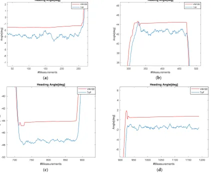
zoom-in view of the heading angle estimation at different rotation states is given in Figure 6(a-d).
Figure 5. Comparison with VN100 AHRS: From 0° to +45°, back to 0° and then to -45°.
(a) (b)
(c) (d)
Figure 6 (a-d).Zoom-in view of heading angle aproximately at 0°, +45°, -45°.
193
194
A
ngle[deg
]
Ang
le[
deg
]
Ang
le[
deg
]
Ang
le[deg
]
Ang
le[deg
The error in heading angle is calculated by comparing angle readings from reference AHRS and
195
that of the proposed method and given in Table 1 below. It is observed that the proposed method of
196
heading angle estimation is more accurate when rotation about the z-axis is minimal. At higher
197
rotation angles (~ +45°), the error in heading angle using ToF sensors is more. The reason is that at
198
oblique angles, the error in range measurements obtained from ToF sensors increases, hence
199
resulting in more error in heading calculation at large rotation angles about vertical.
200
Table 1. Accuracy of proposed scheme.
201
Rotation state VN100 [deg] ToF [deg] Error [deg]
0
0
≈ -1.80 -2.80 1.00
0 45
≈ + -44.2 -47.1 2.90
0
0
≈ 0.60 -1.40 0.80
0 45
≈ − 44.40 42.60 1.80
0
0
≈ -1.80 -2.80 1.00
202
5.2.3D Position and Orientation: Dynamic test
203
204
The 3D localization of sTetro is calculated with staircase geometry and measurements from
205
onboard distance/range sensors only. The geometry of the staircase used and some parameters of
206
ToF sensors and the sTetro robot are given in Table 2 below.
207
208
Table2. Staircase geometry and sTetro’s main parameters
209
Parameters Value(cm) Remarks
Riser height(rl) 14
Tread length(tl) 32
Reliable range (max) 120
sTetro size (l,w,h) 45×20×40
No. of steps(N) 16
Staircase size 480×205×165 (L×W×H)
210
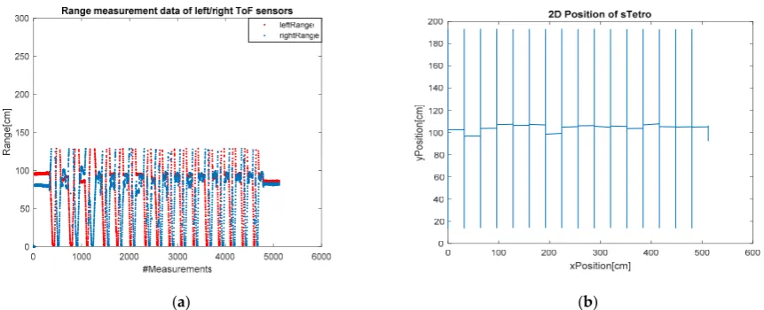
It is observed that reliable ranging from left and right ToF sensors is only about 120 cm. Above
211
this, the range data is not reliable for position calculation in this experiment, as confirmed from the
212
range measurement data in Figure 7 (a). Starting from almost middle of the first step of staircase, the
213
robot’s initial position is set as (x0 =0,y0 =Y z0, 0 =0). The robot is then moved rightwards until its
214
right bumpers touch right wall string of the staircase. The distance measurements from right side
215
ToF sensor give y-position as the robot moves rightwards, keeping x-position and z-position
remain constant( . . i e x=const.,y=const.,z z= j). After the lift-up action is complete, the robot
222
moves forward to the middle of the tread to start next traverse on the stair step. During this forward
223
motion, it’s x-position changes while y-position and z-position remain constant
224
( . . i e x x y= j, =const.,z=const.) . Note that during the left/right travel on the stair, if range
225
measurement increases the maximum limit, then y-position is calculated using the other side’s ToF
226
sensor measurement, by subtracting its range measurement from total width (W) of the staircase.
227
228
The raw range measurements of the left and right ToF sensors are given in Figure 7 (a). These
229
range measurands become unusable after about 120 cm. Measurements from both the left and right
230
range sensor are used to calculate y-position of the robot. The 2D position (x,y) of sTetro is shown in
231
Figure 7 (b). The robot travels about 480 cm in the x-axis and 180 cm in the y-axis (excluding robot
232
width from y-axis distance calculation). The 3D position plot is given in Figure 8. It is evident that all
233
axis position data is very smooth and highly accurate when compared with actual
234
geometry(dimensions) of the staircase. In z-axis, the robot covers approximately 165 cm, as shown in
235
this figure. The heading angle estimation is shown in Figure 9. It is seen that that absolute
236
orientation remains within +1° while traversing the entire staircase. The standard deviation
237
calculated of the heading error is approximately 0.9 degree. The misalignment correction was not
238
implemented in this experiment.
239
240
(a) (b)
Figure 7. (a) Raw range measurements of left and right distance sensor. (b) 2D position (x,y) of sTetro.
241
Figure 8. 3D absolute position (x,y,z) plot of sTetro on 16-step staircase.
244
245
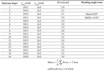
5.3. Error analysis
246
247
Error in heading angle is due to the error in range measurements of the sensor itself. It is noted
248
that range error is about +3cm which contribute to an error in heading angle about +1°. We
249
compared heading angle accuracy with off-the-shelf AHRS sensor (VN-100) from VectorNav Inc. in
250
experiments conducted in this work. The absolute heading angle estimation with the proposed
251
scheme and its error w.r.t reference AHRS sensor is given in Figure 9 below.
252
253
Figure 9. Absolute heading angle estimation of sTetro.
254
(
max min)
[ W]
Error W= − y −y +R
HereW is the width of the stair step,RWis the width of robot and
y
min,
y
max are the minimum and261
maximum range measurements of left/right ToF sensors on a particular step. On each step, the
262
difference between the maximum and minimum range measurements (by adding robot width as
263
well) gives distance covered on a tread. The error is calculated by subtracting this difference from
264
the manually measured width of the stair.
265
266
Table 3. Accuracy of proposed scheme.
267
Staircase Step#
y
max(
cm
)
y
min(
cm
)
Error cm[ ] Heading angle error1 193.1 14.0 2.9
2 193.0 14.1 3.1
3 193.2 14.3 3.1 Mean=0.99°
4 193.1 14.1 3.0 StdDev.=0.93°
5 192.9 14.2 3.3
6 193.1 14.3 3.2
7 193.0 14.3 3.3
8 193.1 13.9 2.8
9 193.1 14.2 3.1
10 193.2 14.1 3.1
11 193.3 14.3 3.0
12 193.1 14.2 3.1
13 192.9 14.0 3.1
14 193.1 14.3 3.2
15 193.2 14.3 3.1
16 193.0 14.0 3.0
1 1
3.1cm
( ) 0.13cm
N i i
i
Mean Error
N stdDev Error
=
= =
=
268
6. Conclusion
269
270
In this work, a novel and a straightforward method is presented to calculate 3D absolute
271
position and orientation using staircase geometry and minimal onboard sensors only. As the stair
272
cleaning robot is assumed to travel in a known environment, so geometry of the staircase is
273
exploited to calculate its position and orientation. The proposed method is very accurate as manual
274
measurements of stair’s riser and tread are provided to the position calculation algorithm. The only
275
uncertainty arrives in y-axis because of the range sensor’s random noise. This noise is minimized by
276
taking the moving average of the measurements of ToF sensors. The error in y-axis only arrives due
to the error in sensor measurement itself (~3 cm as per datasheet). Mean error in position in 3.1 cm
278
with a standard deviation of 0.13 cm only. The mean error in heading angle is 0.99 degree with a
279
standard deviation of 0.93 degree. Ideally, the heading angle of sTetro robot should remain within +5
280
degrees in order to keep aligned with the front step riser. The proposed method faithfully fulfills this
281
requirement. As a future work, this method may be integrated with other indoor positioning
282
systems for overall system redundancy and reliability enhancement.
283
284
Author Contributions: Muhammad Ilyas conceived the main idea presented in this article and wrote most of
285
the part of this paper.Vinu Sivanantham and Manojkumar Devarassu helped in setting up experiments and
286
provided some of the figures. Balakrishnan Ramalingam helped to conduct experiments and result analysis.
287
This worked in done under the supervision of A/Prof. Mohan Rajesh Elara.
288
289
Conflicts of Interest: The authors declare that there is no conflict of interests regarding the publication of this
290
paper.
291
Funding: This work is financially supported by the National Robotics R&D Program Office, Singapore, under
292
the Grant No. RGAST1702.
293
294
295
References
296
297
[1] M. Ilyas, K. Cho, S. H. Baeg, and S. Park, “Drift reduction in IMU-only pedestrian navigation
298
system in unstructured environment,” 2015 10th Asian Control Conf. Emerg. Control Tech. a
299
Sustain. World, ASCC 2015, 2015.
300
[2] M. B. K. W. George, “A Navigation Control System for an Autonomous Mobile Robot,” in
301
Robotics and Factories of the Future ’87, Springer, Berlin, Heidelber, 1988, pp. 678–686.
302
[3] F. A. X. Da Mota, M. X. Rocha, J. J. P. C. Rodrigues, V. H. C. De Albuquerque, and A. R. De
303
Alexandria, “Localization and navigation for autonomous mobile robots using petri nets in
304
indoor environments,” IEEE Access, vol. 6, pp. 31665–31676, 2018.
305
[4] T. S. Wolfram Burgard, Dieter Fox, Daniel Hennig, “Estimating the absolute position of a
306
mobile robot using position probability grids,” Proc. Thirteen. Natl. Conf. Artif. Intell., no.
307
March, pp. 1–15, 1996.
308
[5] P. Goel, S. I. Roumeliotis, and G. S. Sukhatme, “Robust localization using relative and
309
absolute position estimates,” Proc. 1999 IEEE/RSJ Int. Conf. Intell. Robot. Syst., vol. 2, pp.
310
1134–1140, 1999.
311
[6] E. M. Gorostiza, J. L. L. Galilea, F. J. M. Meca, D. S. Monzú, F. E. Zapata, and L. P. Puerto,
312
“Infrared sensor system for mobile-robot positioning in intelligent spaces,” Sensors, vol. 11,
313
no. 5, pp. 5416–5438, 2011.
314
[7] J. Borenstein, H. R. Everett, L. Feng, and D. Wehe, “Mobile robot positioning: Sensors and
315
techniques,” J. Robot. Syst., vol. 14, no. 4, pp. 231–249, 1997.
316
[8] M. B. Alatise and G. P. Hancke, “Pose estimation of a mobile robot based on fusion of IMU
317
data and vision data using an extended kalman filter,” Sensors (Switzerland), vol. 17, no. 10,
318
2017.
319
[9] B.-S. Cho, W. Moon, W.-J. Seo, and K.-R. Baek, “A dead reckoning localization system for
320
mobile robots using inertial sensors and wheel revolution encoding,” J. Mech. Sci. Technol.,
Robot., no. September, pp. 390–397, 2016.
328
[12] J. Biswas and M. Veloso, “WiFi localization and navigation for autonomous indoor mobile
329
robots,” in 2010 IEEE International Conference on Robotics and Automation, 2010, pp. 4379–4384.
330
[13] J. Lim, S. Lee, G. Tewolde, and J. Kwon, “Indoor localization and navigation for a mobile
331
robot equipped with rotating ultrasonic sensors using a smartphone as the robot’s brain,”
332
IEEE Int. Conf. Electro Inf. Technol., vol. 2015–June, pp. 621–625, 2015.
333
[14] D. Xu, L. Han, M. Tan, and Y. F. Li, “Ceiling-based visual positioning for an indoor mobile
334
robot with monocular vision,” IEEE Trans. Ind. Electron., vol. 56, no. 5, pp. 1617–1628, 2009.
335
[15] T. J. Lee, C. H. Kim, and D. I. D. Cho, “A Monocular Vision Sensor-Based Efficient SLAM
336
Method for Indoor Service Robots,” IEEE Trans. Ind. Electron., vol. 66, no. 1, pp. 318–328, 2019.
337
[16] S. Park and S. Hashimoto, “Autonomous navigation system for mobile robot using randomly
338
distributed passive RFID tags,” IEICE Trans. Fundam. Electron. Commun. Comput. Sci., vol.
339
E93–A, no. 4, pp. 711–719, 2010.
340
[17] C. Falsi, D. Dardari, L. Mucchi, and M. Z. Win, “Time of arrival estimation for UWB localizers
341
in realistic environments,” EURASIP J. Appl. Signal Processing, vol. 2006, pp. 1–13, 2006.
342
[18] A. Tedeschi, S. Calcaterra, and F. Benedetto, “Ultrasonic RAdar system (URAS): Arduino and
343
virtual reality for a light-free mapping of indoor environments,” IEEE Sens. J., vol. 17, no. 14,
344
pp. 4595–4604, 2017.
345
[19] M. Ilyas, S. Yuyao, R. E. Mohan, M. Devarassu, and M. Kalimuthu, “Design of sTetro : A
346
Modular , Reconfigurable , and Autonomous Staircase Cleaning Robot,” vol. 2018, 2018.
347
[20] “Tetris game,” https://en.wikipedia.org/. ((accesses on 2 Feb. 2018).
348
[21] “Vl53L0X”, https://www.pololu.com/product/2490, (accesses on 10 April. 2018).
349
[22] “VN100 MEMS IMU”, https://www.vectornav.com/products/vn-100, (accesses on 8 Oct,
350
2018).