Computational Modelling of Transonic
Circulation Control
Thesis submitted in accordance with the requirements of the University of Liverpool for the degree of Doctor in Philosophy
by
Matthew J. Forster August 2017
c
Declaration
I hereby declare that this dissertation is a record of work carried out in the School of Engineering at the University of Liverpool during the period from September 2013 to August 2017. The dissertation is original in content except where otherwise indicated.
August 2017
... (Matthew J. Forster)
Abstract
This Ph.D. thesis focusses upon computational fluid dynamics simulations of circula-tion control in transonic freestream speeds for applicacircula-tions to unmanned combat air vehicles. The work addresses Coanda shape designs and their effectiveness for transonic circulation control using supersonic jets, with comparisons against traditional control surfaces. Previous works have thus far only investigated transonic circulation control on elliptical sectioned wings with unrepresentatively thick trailing edges and improve-ments in performance made by considering elliptical Coanda devices or increasing radii of curvature. In this work, a supercritical aerofoil was first modified to accommodate a small Coanda surface with minimal effects on the base drag and a comparison made between the performance of using several Coanda designs and a hinged control surface. The use of a step was demonstrated to make a circulation control device with a simple converging nozzle as effective as ailerons and flaps up to moderate deflection angles and that the limitations are due to breakdowns in the mean flow in a similar fashion to traditional devices. In addition an optimisation study was performed using modern numerical methods on the contouring of the Coanda surface, which identified a shape that performed well for both transonic and subsonic freestream conditions. Circulation control was then applied to a three-dimensional unmanned combat air vehicle plan-form and assessed at transonic conditions for use in roll, pitch and yaw control. From the range of conditions investigated the findings suggest that, for a three-dimensional representative geometry, circulation control can match the performance of conventional controls for roll and pitch. The results also suggest that for benign transonic conditions, circulation control can also provide control similar effectiveness to split flaps for yaw control. The findings open up insights into transonic circulation control and hopefully will promote further research in both academia and industry, where a lack of CFD validation quality experimental data for a transonic test case with supersonic blowing prohibits the technology from advancing.
List of Publications
Journal Papers
Forster, M and Steijl, R, “Design Study of Coanda Devices for Transonic Circulation
Control,”The Aeronautical Journal, July 2017, DOI: 10.1017/aer.2017.65.
Conference Papers
Forster, M and Steijl, R, “Numerical Simulation of Transonic Circulation Control,”53rd
AIAA Aerospace Sciences Meeting, Kissimmee Florida, American Institute of Aeronau-tics and AstronauAeronau-tics, 5th-9th Jan 2015, DOI: 10.2514/6.2015-1709.
Forster, M, Biava, M and Steijl, R, “Optimisation of Coanda Surfaces for Transonic
Cir-culation Control,”6th European Conference for Aerospace Sciences (EUCASS), Krakow
Poland, July 2015, DOI: 10.13140/RG.2.1.3675.8242.
Forster, M, Biava, M and Steijl, R, “Multipoint Optimisation of Coanda Surfaces
for Transonic Circulation Control using the Adjoint Method,” 8th AIAA Flow
Con-trol Conference, Washington DC, American Institute of Aeronautics and Astronautics, 13th-17th June 2016, DOI: 10.2514/6.2016-3773.
Forster, M and Steijl, R, “Circulation Control for High-Speed Unmanned Combat Air
Vehicles,”2016 Applied Aerodynamics Conference, Bristol UK, Royal Aeronautical
Acknowledgements
I would like to offer my gratitude for all of the help and advice offered by my supervisor Dr. Ren´e Steijl throughout my Ph.D.. My secondary supervisor Prof. Ken Badcock has often offered a voice of reason in our progress meetings together. Dr. Massimo Biava has been invaluable not only for the development of the Adjoint solver that facilitated the optimisation work within this project. Many thanks to Prof. George Barakos for providing the facilities, software and licences to undertake this work, and also to Dr. Mark Woodgate for his support and giving me the keys when I was locked out.
My thanks also extend to Dr. George Hoholis for his prior work on CC, the geometry modifications and building of the initial grid topology for the work involved on the SACCON. The regular meetings with Prof. Clyde Warsop from BAE Systems, Dr. Bill Crowther and his Ph.D. students from Manchester University, as part of the Future Combat Air Systems Focussed Research (FFR) project, often provided a helpful source of critique which shaped the direction of my research. I am also fortunate to have been a participant in the NATO AVT-239 task group, where the wider flow control community offered insights and kindled ideas for future research.
I would like to thank the university staff who often go unthanked for their hard work. In particular Dr. Cliff Addison and Dave Love from the advanced research computing department; Maria White, Lesia Swain and Jack Carter-Hallam from the engineering school; Helen Hall and the inter-library loans department; and building managers Pamela Ambrose, Mark Jewell and Tommy Graham.
In addition, thank you to all the members of the CFD Lab and office who have made the environment an enjoyable place to work: Antonio, Becky, Cathy, Chris, Clement, Dan, Dave, Florent, Fulvio, Gaetan, George, Giampaolo, Giulia, Jade, Luke, Marina, Mark, Mike, Mike, Mikolaj, Neale, Paul, Philipp, Reik, Savio, Sebastian, Sebastiano, Shenren, Simone, Tom and Vladimir. Finally, my thanks and love to Silvia and my family for putting up with me and keeping me sane throughout this time.
This work was jointly funded by the University of Liverpool through the EPSRC Doctoral Training Partnership (grant number 1362153), and BAE Systems as part of the Ministry of Defence FFR programme. The use of the Chadwick HPC facility at the University of Liverpool and the Polaris N8 HPC is greatly appreciated.
Contents
Declaration iii
Abstract v
List of Publications vii
Acknowledgements ix Contents xiii List of Figures xx Nomenclature xxiii 1 Introduction 1 1.1 Circulation Control . . . 1 1.2 Momentum Coefficient . . . 5
1.3 Effect of Coanda Geometry on Supersonic Coanda Jet Attachment . . . 5
1.3.1 In transonic freestream . . . 6
1.3.2 Without freestream . . . 16
1.4 Sweep Effects on CC . . . 22
1.5 Numerical Studies on Circulation Control . . . 24
1.5.1 Subsonic . . . 24
1.5.2 Transonic . . . 25
1.5.3 Optimisation . . . 25
1.6 Numerical Studies on Aspects of Transonic Circulation Control . . . 27
1.6.1 Supersonic Coanda without freestream . . . 27
1.6.2 Compressible free-shear layers . . . 27
1.6.3 Shock boundary layer interactions . . . 29
1.7 NATO AVT-239: Innovative Control Effectors for Manoeuvring of Air Vehicles . . . 30
1.9 Aims and Objectives . . . 32
1.10 Thesis Outline . . . 33
2 Numerical Methods 35 2.1 Navier–Stokes Equations . . . 36
2.2 Reynolds Averaged Navier–Stokes Turbulence Modelling . . . 37
2.2.1 Wilcox k–ω model . . . 38
2.2.2 Menter k–ω SST model . . . 38
2.2.3 Explicit algebraic Reynolds stress model . . . 39
2.3 Adjoint Equations . . . 42
2.4 Nondimensionalisation . . . 43
2.5 Reservoir Boundary Condition . . . 44
2.6 Gradient Based Optimisation . . . 45
2.6.1 Optimisation routine . . . 46
2.6.2 Mesh deformation . . . 46
2.7 Meshing Approach . . . 47
3 Validation 51 3.1 NASA 6% Transonic Circulation Control . . . 51
3.1.1 Boundary and initial conditions . . . 53
3.1.2 Multiblock structured grid . . . 53
3.1.3 Results . . . 58
3.2 Gregory-Smith Experiments - Stepped Supersonic Coanda Jets in Still Air 65 3.2.1 Model and boundary conditions . . . 67
3.2.2 Results . . . 70
3.3 Summary of Results . . . 83
4 Design Study of Coanda Devices for Transonic CC 85 4.1 Transonic Flow Over a Supercritical Aerofoil with Aileron Deflection . . 85
4.2 Evaluation of Coanda Designs in Transonic Flow . . . 88
4.2.1 Grid refinement . . . 90
4.2.2 Converging nozzle with 10:1 radius to slot ratio (10:1 Convg) . . 91
4.2.3 Converging nozzle with 21:1 radius to slot ratio (21:1 Convg) . . 93
4.2.4 Converging-diverging nozzle with 21:1 radius to slot ratio (21:1 Condi7) . . . 93
4.2.5 Converging nozzle with a 20:1:1 radius to slot to step ratio (20:1:1 Step) . . . 95
4.2.6 Effect of angle of attack . . . 95
5 Optimisation 101
5.1 Parametrisation . . . 101
5.2 Baseline Circular Coanda . . . 103
5.3 Single Point Optimisation . . . 103
5.3.1 High speed case (HSOPT) . . . 103
5.3.2 Low speed case (LSOPT) . . . 106
5.4 Multi-Point Optimisation (MPOPT) . . . 106
5.5 Off-Design Behaviour . . . 108
5.6 Surface Sensitivities . . . 110
5.7 Summary of Results . . . 113
6 SACCON 115 6.1 SACCON Geometry and Grid . . . 115
6.1.1 Half span force reduction . . . 118
6.2 Grid Convergence . . . 118
6.3 SACCON Pitch-up Behaviour . . . 119
6.4 Jet Attachment . . . 120
6.4.1 Coanda without step . . . 120
6.4.2 Coanda with step . . . 120
6.5 Comparison of Stepped CC with Flaps . . . 122
6.6 CC for Roll, Pitch and Yaw Control . . . 125
6.7 Summary of Results . . . 126
7 Conclusions 131 7.1 Validation . . . 131
7.2 2D Design Study of Coanda Surfaces . . . 132
7.3 Optimisation . . . 132
7.4 SACCON . . . 133
7.5 Recommendations for Further Work . . . 133
Bibliography 135
A Table of single point optimisation parameters 145
List of Figures
1.1 Streamlines showing separation point with blowing over Coanda. . . 2
1.2 Schematic of flows at trailing edge. . . 3
1.3 Maximum lift obtained by Englar with different Coanda geometries at range of Mach numbers for Cµ≤0.08. . . 7
1.4 Englar trailing edge geometries: Jet flap, rounded ellipse and pure ellipse. 8 1.5 Lift coefficient versus momentum coefficient at a constant freestream Mach number using the 103LS Coanda. . . 13
1.6 NCCR1610-8054 CC aerofoil section. . . 14
1.7 NCCR1610-8054 trailing edge geometries, 103LS, 103XW and 103DE. . 14
1.8 Comparison of performance of three Coanda devices at M=0.6 on the NCCR1610-8054 CC model. . . 14
1.9 Effect of upper surface shock on the NCCR1610-8054 103XW CC exper-iment. . . 15
1.10 Coanda geometries used in the experiment. . . 15
1.11 Coanda flare geometry. . . 17
1.12 Schlieren of unstepped (a and b), and stepped (c) supersonic Coanda jets near detachment. . . 18
1.13 Schematic of stepped Coanda geometries. . . 18
1.14 RMS sound pressure against jet pressure ratio. . . 19
1.15 Schematic showing production of discrete tones. . . 20
1.16 Schematic of flow over sawtooth slot exit on axisymmetric Coanda. . . . 21
1.17 RMS sound pressure against jet pressure ratio with saw-tooth profile. . 21
1.18 Irrotational vortex theory for attachment of supersonic Coanda jets. . . 22
1.19 Velocity components in the streamwise direction of 45◦ swept CC model at M = 0.7,α= 0 and NPR=1.4. . . 23
1.20 Comparison of swept (solid symbols) and unswept (open) at M=0.7 swept and M=0.5 unswept forCµ= 0.03. . . 24
1.22 Compressible shear layer growth rates vs convective Mach numberMc=
(u1−u2)/(a1+a2). . . 28
2.1 Diagram of trailing edge of circulation control aerofoil. The solid lines are considered as external surfaces, dotted lines are the internal plenum surfaces and the dashed line is the reservoir boundary condition. . . 45
2.2 Flow chart of the multipoint optimisation process. . . 47
2.3 Examples of blocking strategy for CC. . . 49
3.1 Schematic of the NASA 6% elliptical circulation control aerofoil. . . 51
3.2 End plate diagram and experimental model photo in the NASA TDT wind tunnel. . . 53
3.3 View of the computational domain showing the boundary conditions used. . . 54
3.4 View of circular end plate and blocking topology in the near-field. . . . 55
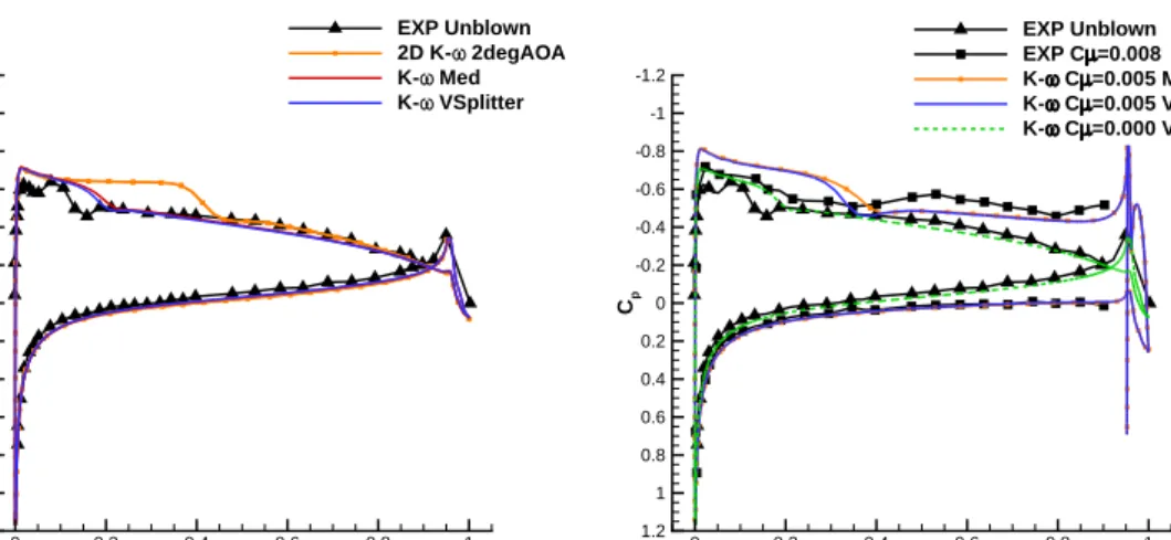
3.5 Coefficients of pressure with blowing atCµ≈0.0051 for block structured grids with approximately 7 , 14 and 28×106 cells, using the standard k−ω turbulence model. . . 56
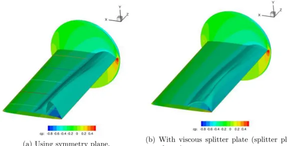
3.6 Grid including the viscous splitter plate. . . 57
3.7 Pressure coefficients comparing the impact of simplifications to the model, with freestream conditions atM = 0.8 and α= 3.0. . . 58
3.8 Isosurfaces of pressure coefficient at critical Cp∗ ≈ −0.43 for M = 0.8, without blowing. . . 59
3.9 Unblown simulated vs experimental pressure coefficients for Mach 0.3 and 0.8 using the fine grid without the splitter plate. . . 60
3.10 Comparing simulated pressure distribution at freestream conditionsM = 0.3 and α= 3 using the grid with the splitter plate. . . 61
3.11 Sectional lift and drag coefficients versusCµ forM = 0.3 . . . 61
3.12 Contours of Mach number near the Coanda surface on the midspan slice forM = 0.8 andα= 3, with the viscous splitter plate. . . 62
3.13 Coefficients of pressure with blowing on the grid with the viscous splitter wall. . . 63
3.14 Coefficients of pressure with blowing at Cµ = 0.007 between EARSM, SST andk−ω turbulence models. . . 64
3.15 Sectional loads comparing predicted and experimental data with respect to the blowing rateCµ. . . 65
3.16 Comparison of the wind (Cl,Cd in symbols) and body (CF Y,CF X in lines) axis force coefficients with respect to the blowing rate Cµ. Force coefficients were computed byCF Y =Clcos(α) +Cdsin(α) and CF X = −Clsin(α) +Cdcos(α). . . 66
3.17 Boundary conditions and model geometry. . . 67 3.18 Computational grids for stepped and unstepped supersonic Coanda
sim-ulation without a freestream. . . 68
3.19 Snapshot of surface pressures over stepped geometry at N P R−1
= 0.235
during unsteady simulation. . . 69
3.20 Example of setting plenum boundary condition. . . 70
3.21 Surface pressures for unstepped and stepped geometries at moderate (a, b) and low (c, d) nozzle pressure ratios. Low pressure ratios here correspond to the published surface pressure data for which the jet was
close to detachment. . . 71
3.22 Comparison of Mach contours for three models without step N P R−1
=
0.257. . . 72
3.23 Comparison of Mach contours with experiment from digitised interfero-gram N P R−1
≈0.3. . . 73
3.24 Nondimensional Contour plots for N P R−1
=0.248. . . 74
3.25 Mach contours near slot with step N P R−1
=0.212. . . 75
3.26 Mach, Reynolds Stress and coefficient of µt profiles without step at 5◦
forN P R−1
=0.257. . . 77
3.27 Mach, Reynolds Stress and coefficient of µt profiles without step at 20◦
forN P R−1
=0.257. . . 78
3.28 Mach, Reynolds Stress and coefficient of µt profiles without step at 25◦
forN P R−1
=0.257. . . 79
3.29 Mach, Reynolds Stress and coefficient of µt profiles without step at 35◦
forN P R−1
=0.257. . . 80
3.30 Mach, Reynolds Stress and coefficient of µt profiles without step at 60◦
forN P R−1
=0.257. . . 81
3.31 Surface pressures at successive nozzle pressure ratios until detachment.
Unstepped model h = 4.15mm, R = 30mm. Experimental detachment
occurred at N P R−1
= 0.251. . . 82
3.32 Surface pressures at successive nozzle pressure ratios until detachment.
Stepped modelh= 4mm,s= 1.5mm,R= 30mmExperimental
detach-ment occurred atN P R−1
= 0.203. . . 83
4.1 Douglas DLBA032 geometry. . . 85
4.2 Effect of grid refinement on lift and drag for simulations of the DLBA032
with (solid lines) and without (dashed) aδ = 3◦
aileron deflection. Here
M ≈0.715,Re= 5×10⁶at angles of attack ofα= 1.183◦
with deflection and α= 1.342◦
without aileron deflection. . . 86
4.3 Experimental and predicted pressure distribution for the DLBA032 with
4.4 Modified geometry with CC device. . . 88
4.5 Diagrams of trailing edge devices. . . 89
4.6 Comparing unblown CC DLBA032 with original shape without aileron
deflection. . . 90
4.7 Effect of grid refinement on the 21:1 Coanda device atN P R= 4.0. . . . 91
4.8 Predicted pressure coefficients for Douglas DLBA032 at α = 1.342◦
,
M = 0.716 and Re = 5.028 ×10⁶ for an aileron deflection and with
blowing atCµ≈0.003,Cµ≈0.004 andCµ≈0.005 for the 10:1
configu-ration. Symbols here represent the simulated pressure distribution of the deflected aileron case at the same freestream conditions and turbulence
model. . . 92
4.9 Comparing lift, drag and pitching moment coefficient characteristics with
blowing over various Coanda surfaces against aileron deflection on the
DLBA032 atM = 0.716, α= 1.342◦
and Re= 5.028×10⁶. . . . 96
4.10 Contours of Mach number for various Coanda designs using thek-ω SST
turbulence model. . . 97
4.11 Profile of Mach numbers for the SST andk-ω models at the slot exit for
the converging diverging configuration with a 21:1 radius to slot ratio at
design condition for blowing at PR7. . . 98
4.12 Mach profile normal to Coanda surface at 3.0h from the slot exit. . . 98
4.13 Effect of angle of attack onCl at M = 0.716 and Re= 5×10⁶. . . 99
4.14 Mach contours at the trailing edge of aileron deflection and CC cases at
α= 5◦
,M = 0.716 andRe= 5×10⁶. Inset shows detail of the trailing
edges, at the same scale in both images. . . 100
5.1 Parametrisation of Coanda surface by a radial distribution of Bernstein
polynomials. . . 102
5.2 Schematic of the baseline and design variable limit parameters. . . 103
5.3 Effect of grid refinement on Cl and Cd at M = 0.716, Re = 5×10⁶,
α= 1.342◦
andN P R= 4.0. . . 104
5.4 Contours of Mach number at the trailing edge of the aerofoil, a red line
indicates the contour of the initial quasi–elliptical Coanda shape. . . 105
5.5 Relative change in lift coefficient increase with respect to every HSOPT
objective function call evaluation from the initial quasi-elliptical shape.
The change is relative to the baseline circular ∆Cl baseline = 0.33. The
horizontal line indicates the maximum achieved when starting HSOPT from a circular shape. . . 105
5.6 Final Coanda geometries following several HSOPT optimisation routines
5.7 Relative change in lift coefficient increase with respect to every LSOPT objective function call evaluation from the initial quasi-elliptical shape.
The change is relative to the baseline circular ∆Cl baseline = 0.69. The
horizontal line indicates the maximum achieved when starting LSOPT from the minimum of the design space. . . 108
5.8 Multipoint optimisation history showing: ∆Cl/∆Clbaseline for M = 0.4,
N P R= 4 (a),M = 0.716, N P R= 4 (b) and M = 0.716, N P R= 6 (c) and F/Fbaseline (d) with comparisons against the results from the single
point optimisation studies. . . 109
5.9 Coanda geometry the initial quasi–ellipse and resulting low speed (LSOPT),
high speed (HSOPT) and multipoint (MPOPT) optimisation designs. . 110
5.10 Comparing the∆Clof the single point optimised design with the circular
shape at off-design conditions,α= 1.342, Re= 5×10⁶. . . 111
5.11 Mach contour lines and surface sensitivities (dCl/dXn) at conditions
M = 0.4, N P R = 4 (left), M = 0.716, N P R = 4 (middle) and
M = 0.716, N P R = 6 (right). Top row: Initial quasi–elliptical shape. Second row: Single point optimisation for the low speed design condition
M = 0.4, N P R= 4. Third row: Single point optimisation for the high
speed design condition M = 0.716, N P R = 4. Fourth row: Multipoint
optimisation. . . 112
6.1 SACCON F17 geometry and reference lengths. . . 116
6.2 Diagram of inboard Coanda (IBC) geometries. . . 116
6.3 Half span grid. Inset shows detail of the trailing edge across the wingspan.117
6.4 α vs Cm for unblown CC, simulated and experimental without flaps. . . 119
6.5 Contours of surface pressure with streamtrace ribbons coloured with
Mach contours at the trailing edge. . . 121
6.6 ∆CLand ∆CD with respect to blowing over from the circulation control
device at the inboard of the left wing (lower slot negative Cµ). . . 122
6.7 Pitch (Cm), roll (Cl) and yaw (Cn) with respect to blowing at the inboard
of the left wing (lower slot negative Cµ). . . 123
6.8 Streamtrace ribbons and surfaceCp with over lower Coanda (IBC-). . . 124
6.9 ∆CL and ∆CD achieved with blowing compared with experiment and
CFD with flaps. Both simulations and experiment were conducted with actuation on the left inboard only. Here black circles represent results from half span simulations of CC merged with unblown half span, while connected squares are with the full span grid. . . 125
6.10 Pitch (Cm), roll (Cl) and yaw (Cn) at a constant rate of blowing over a
range of angles of attack. Here black circles represent results from half span simulations of CC merged with unblown half span, while connected squares are with the full span grid. . . 126
6.11 Streamtrace ribbons and surfaceCp with over both Coanda slots (IBC±).127
6.12 Difference in Cp with unblown case for blowing over LIBC- at NPR=3,
Cµ = −2.2×10⁻⁴. The left image shows the upper surface, while the
right shows the lower. . . 128
6.13 Difference inCp with unblown case for blowing over LIBC+ at NPR=3,
Cµ= 2.2×10⁻⁴. The left image shows the upper surface, while the right
shows the lower. . . 129 6.14 Contours of surface pressure with streamtrace ribbons coloured with
Mach contours atα= 10◦
. . . 130
6.15 Tip vortex atα= 10◦
Nomenclature
α Angle of attack
δ Control surface deflection angle
A Wing surface area
c Chord length
Cd 2D Sectional drag coefficient
Cl 2D Sectional lift coefficient
Cm 2D Sectional pitching moment coefficient
CD 3D Drag coefficient
CL 3D Lift coefficient
CS 3D Side force coefficient
Cl 3D Pitch moment coefficient
Cm 3D Roll moment coefficient
Cn 3D Yaw moment coefficient
Cµ Momentum coefficient, ˙mjVj/q∞A
Cp Pressure coefficient
∆CL/Cµ Lift augmentation ratio
dCl/dXn Change in lift coefficient with respect to normal surface displacement
h Slot height
M Freestream Mach number
˙
mj Jet mass flow rate
µ Dynamic Viscosity
ν Kinematic viscosity
Ω Vorticity magnitude
P0 Plenum (total) pressure
P∞ Freestream (static) pressure
q∞ Freestream dynamic pressure
r Coanda radius
Re Reynolds number
ρ Density
s Step height
Sij i,j component of the mean strain tensor
τ Reynolds stress tensor
¯
u Time average velocity component
u′
Fluctuating velocity component
Vj Jet velocity magnitude
y+ Non-dimensional wall distance,y
r ∂u ∂y ν Abbreviations
AOA Angle of Attack
AVT Applied Vehicle Technology
CC Circulation Control
CFD Computational Fluid Dynamics
DTNSRDC David W. Taylor Naval Ship Research and Development Center
EARSM Explicit Algebraic Reynolds Stress Model
EXP Experiment
HSWT High Speed Wind Tunnel
IBC Inboard Coanda
MRP Moment Reference Point
NCCR Navy Circulation Control Rotor
NPR Nozzle Pressure Ratio, P0/P∞
RANS Reynolds Averaged Navier-Stokes
SACCON Stability and Control Configuration
SBLI Shock Boundary Layer Interaction
TDT Transonic Dynamics Tunnel
Chapter 1
Introduction
1.1
Circulation Control
In aircraft, ailerons have traditionally been used to alter the circulation around the wings to generate additional forces about the wings for flight control. Flaps employ a similar principle and are used as high lift devices for take-off and landing. An alternative method is circulation control (CC) using the Coanda effect; a jet of air is blown over a rounded trailing edge of a wing. CC using blowing offers advantages over devices such as flaps and ailerons, removing the necessity of moving parts, possibly leading to a reduction in aircraft weight [1].
Circulation is defined as the line integral of velocity about a closed loop within a
fluid, Γ =H
v.dl. The Kutta-Joukowski theorem relates circulation to lift and states
that the lifting force on a body acts normal to the freestream velocity (U∞) and is
equal to L = −ρ∞U∞Γ, where ρ∞ is freestream density. For aerofoils with a sharp
trailing edge in a potential flow, Γ is equal to the amount of circulation necessary to
fix the stagnation point at the trailing edge, often known as the Kutta Condition. The trailing edge separation is not uniquely defined for an aerofoil with a rounded trailing edge. However, in a real viscous flow the separation would be dependent on flow conditions such as Reynolds number, angle of attack, and trailing edge radius. CC utilises the Coanda effect to manipulate the separation point and alter the circulation. An illustration of the streamlines at the trailing edge of a CC aerofoil is shown in Fig. 1.1. With blowing over the upper side of the Coanda surface the stagnation point is moved further around the Coanda as would have been for the unblown case.
The Coanda effect describes the behaviour of a fluid moving tangentially to a convex (typically circular) surface. The flow attaches to the curved surface as a result of the pressure gradients within the jet flow (see Fig. 1.2a). The position of the separation
Figure 1.1: Streamlines showing separation point with blowing over Coanda [2].
and stagnation points at the trailing and leading edges of the aerofoil are altered due to blowing a jet over the Coanda surface by an increase in circulation, and therefore lift is increased.
CC requires a high speed jet of air which attaches to the Coanda surface, potentially operating at jet speeds up to 4 times the freestream speed [3–5]. As this high speed jet meets the relatively lower speed air in the freestream, the jet entrains the fluid within the freestream which is then also turned around the Coanda. The entrainment is due to the mixing within a shear layer between the jet and the freestream travelling at significantly different speeds and Mach numbers. Figures 1.2b and 1.2c show simplified schematic diagrams of the flows that occur at the slot exit and just downstream of the slot. The momentum of the jet influences the boundary layer at the trailing edge of the wing and accelerates the local freestream flow.
For aerofoils in the transonic regime, a supersonic Coanda jet is necessary to achieve a significant change in lift. In addition to shear layers there is a possibility of shock boundary-layer interactions occurring on the surface of the Coanda devices, if the jet becomes under-expanded [6]. Depending on the severity of the shock boundary layer interaction, the jet can detach completely from the Coanda surface [7]. At transonic speeds, the shock on the upper surface of the aerofoil also alters the boundary layer flow leading to the CC device at the trailing edge (Fig. 1.2b), which can affect the behaviour of the Coanda jet flow [8].
For an aircraft to successfully use a CC system it would need to be effective over a wide range of flight conditions, including different altitudes. Changes in altitude as well as engine settings will create differences in the pressure ratio the Coanda device is operating at. Therefore, it is crucial to consider the CC device for a wide range of pressure ratios, mainly a range of conditions with under-expansion and, for cases where a converging-diverging nozzle is used, also over-expansion cases.
Studies on transonic freestream CC have shown that the shape of the Coanda surface plays an important role in the effectiveness of the CC device at transonic freestream
(a) Trailing edge CC [3].
Minf Mjet
(b) Slot exit flow
Minf Mjet
(c) Shear layer downstream of slot
Figure 1.2: Schematic of flows at trailing edge.
speeds [3,4,8,9]. Parameters such as the slot height to (local) Coanda radius ratio affect the attachment of the Coanda jet, and the range of blowing rates (and nozzle pressure ratios) for which the jet remains attached to the Coanda. Experimental investigations into elliptical Coanda surfaces have concluded that more eccentric ellipses and smaller slot heights perform most favourably in transonic flows [3, 4, 9].
Alternative methods of promoting supersonic Coanda jet attachment have been studied in conditions without a freestream flow. Converging-diverging nozzles have been shown to increase the detachment pressure ratio [10, 11] by expanding the jet flow further than a converging nozzle and limiting under-expansion. Additionally, the introduction of a step between the Coanda surface and the jet exit of a converging nozzle also increased the detachment pressure ratio [12, 13].
CC using the Coanda effect for use as a means of generating an increase in lift over an aerofoil has been in consideration for at least 60 years [14]. Significant focus was invested on improving the lift of rotor blades with elliptical sections amid development of the X-Wing CC helicopter concept in the early 1980s [15]. The X-Wing concept proposed to take off vertically using the rotor blades, but for forward flight the rotor blades would be fixed and lift generated using circulation control on the rotors. More recently, with concerns over aircraft efficiency and environmental impacts, CC has been studied to improve the lifting capabilities of fixed wing aircraft while keeping within the capabilities of existing airport infrastructures [16]. On fixed wing UAVs, it has been shown in subsonic flight that CC has the potential to replace moving parts for manoeuvrability control [17]. Other active flow control systems are also being studied such as; using sweeping jets to reduce the vertical tail size of commercial aircraft [18,19], blowing over flaps for drag reduction [20], and using plasma actuators for circulation control [21].
Much of the research to date on CC using blowing has investigated flow control devices on aerofoils in the low speed subsonic flight regime. As a result, modern nu-merical studies on circulation control have heavily relied on these subsonic freestream circulation control experiments [22–25], such as those at the Georgia Tech Research Institute, which were intended specifically for CFD validation and had a trailing edge
radius of approximately 10% chord [25]. This experiment demonstrated significant wall interference and angle of attack corrections to be suitable for CFD simulations [25].
Research of CC in transonic freestreams has produced a handful of experiments and numerical studies, which mostly took place in the 1980s on aerofoil sections intended to be used for helicopter blades on the X-Wing CC concept [4, 5, 8, 26]. Such experi-ments were conducted in moderate size wind tunnels, which introduced significant wall interference effects [27]. The elliptical X-Wing type sections typically had maximum thicknesses of approximately 15% chord, which do not have the characteristics of a supercritical aerofoil, as would be used on a fixed wing aircraft. A supercritical CC aerofoil has been developed [23], however transonic experiments on this section have not yet been published.
The difference between CC at subsonic and transonic freestream speeds is high-lighted in Fig. 1.3, showing the lift obtained by Englar [4] for an elliptical CC aerofoil over a range of Mach numbers. At low speeds, the “Rounded Ellipse” CC aerofoil outperformed the purely elliptical section, however at high speeds this was not the case. Schlecht and Anders [9] found that an elliptical Coanda surface was superior to a biconvex surface for both low subsonic and transonic freestreams, since the separation point of the jet is fixed by the sharp profile of the biconvex Coanda.
Alexander et. al. [3] recognised a void in the public domain of data for transonic
circulation control aerofoils, specifically those intended for fixed wing aircraft. Experi-ments were conducted on a 6% thick elliptical aerofoil in the NASA transonic dynamics
tunnel for freestream conditions up toM = 0.84. Several elliptical Coanda shapes were
compared, and it was found that at higher freestream Mach numbers, the Coanda
shapes with larger major to minor axis ratios gave a greater ∆Cl. The findings from
this experiment will be further discussed in Section 1.3.
Numerical studies of the X-Wing era often used coupled inviscid-viscous solvers [15, 28, 29] or two dimensional Navier-Stokes solvers with algebraic turbulence models [27,30]. There remains a distinct lack of comprehensive numerical studies using modern techniques for transonic circulation control. As a result, fundamental problems such as grid requirements and turbulence modelling remain largely unanswered.
The deficiency in transonic flow control research is also highlighted by Millholen
et. al.[20] when discussing the fundamental aerodynamics subsonic/transonic-modular active control (FAST-MAC) aircraft model. It is stated that the experiments on the FAST-MAC are unique as it will evaluate flow control strategies at transonic speeds [20]. The FAST-MAC uses a blown flap configuration to enhance lift for take off and landing, and will utilise blowing at cruise for drag reduction.
1.2
Momentum Coefficient
The supply of air for the plenum for circulation control is often taken from bleed air from the jet engine of the aircraft [17]. As a result of this the efficiency of the circulation control device is critical; mass flow taken from the engine reduces the power available
for forward thrust. The jet momentum coefficient (Cµ) is often used as a measure of
blowing over a circulation control device, which is defined as
Cµ=
˙
mjVj
q∞A
(1.1)
where ˙mj is the mass flow rate through the slot exit and A is the surface area of the
aerofoil. In circulation control experiments, ˙mj is usually measured using a flow venturi
meter andVj calculated from isentropic equations using the plenum pressure.
An important and widely used metric for defining the efficiency of a CC system is
the lift augmentation ratio ∆CL/Cµ. Alexander et. al. state that CC performance
is considered as “good” for ∆CL/Cµ > 50 [3] in a transonic freestream. In their
experiments on the 6% thick elliptical wing they found a maximum augmentation ratio
of 37 for M = 0.8. In addition Abramson and Rogers [8] achieved ∆CL/Cµ = 27 at
M = 0.7 and∆CL/Cµ= 10 atM = 0.8 on their 16% thick elliptical aerofoil.
1.3
Effect of Coanda Geometry on Supersonic Coanda
Jet Attachment
For Coanda flares and some instances of flow control (such as circulation control in the transonic flight regime) the jet over the Coanda surface is typically supersonic and often under-expanded. The jet expands immediately downstream of the slot exit, followed by a series of shock waves which interact with the free shear layer between the outer flow (either quiescent, or freestream in the case of circulation control) and the jet. These waves also interact with the boundary layer on the Coanda surface, separating the boundary layer in the form of shock boundary layer interactions (SBLIs). At moderate blowing rates, the separation is limited to a recirculation bubble, however for more highly under-expanded jets, the shock waves are strong enough to completely detach (or breakaway) the jet from the Coanda surface [7].
The literature shows that the shape of the Coanda surface has an effect on the attachment of the jet. In transonic freestream flows, experimental studies have mostly investigated the change in lift due to elliptical Coanda devices. Experiments using supersonic jets without a freestream, such as for Coanda flares or for bench tests of Fluidic Thrust Vectoring the focus has been to eliminate the detachment due to
under-expansion of the jet.
1.3.1 In transonic freestream
Of the few investigations into transonic circulation control available in the literature, most were designed such that an assessment of trailing edge geometries could be inves-tigated using the same baseline wing/aerofoil model. Many of these experiments were conducted in relatively small wind tunnels, often with porous or slatted walls limiting their suitability for use as CFD validation cases. Despite this, however, lessons can be learnt from these investigations which are summarised in Table 1.1.
Englar 1970
Englar [4] was one of the first to show the difference between several Coanda geometries for transonic CC at the David W. Taylor Naval Ship Research & Development Center (DTNSRDC). The experiments conducted by Englar on an 8 inch, 15% thick elliptical
model in the 12×16 inch tunnel, considered three different trailing edges: a circular
(denoted rounded ellipse), elliptical and a jet flap up to freestream Mach numbers of
M = 0.9.
Figure 1.4 shows the geometries that were considered by Englar. The elliptical and jet flap trailing edge shapes were constructed using the original elliptical aerofoil contour, however the model was truncated by 0.3 inches (3.75% chord) to accommodate the circular Coanda geometry. The circular Coanda geometry had a 4% chord Coanda radius while the ellipse had an aspect ratio of 1.97:1 with 4% chord semi-minor and 7.88% chord semi-major axes. As shown in Fig. 1.4, the slot position for the circular and elliptical Coandas were the same. All geometries had slot heights of 0.01 inches and used a converging nozzle. This corresponds to radius to slot height ratios of 31 for the circular geometry and 120 at the slot exit of the elliptical Coanda device.
Englar found that forM >0.7,Clwhen using the elliptical Coanda was twice that
of the circular, and a maximum lift augmentation ratio of ∆Cl/Cµ= 43 was achieved
compared with ∆Cl/Cµ= 34 for the circular device. For subsonic speeds, the circular
device was more effective than the ellipse. The jet flap was least effective as a lift augmentation device, as shown in Fig. 1.3.
Figure 1.3: Maximum lift obtained by Englar with different Coanda geometries at range
Year Author Geometry Re/c (×106) δ (%c)1 Mach Trailing Edge Rc (%c)2 h (%c) 5 Rc/h TH6 1970 Englar [4] 15% Elliptical (2D) 1.5−2.5 1.94% 0.3−0.9 Circular 3.875% 0.125% 31 7.5% 1.97:1 Ellipse 15.5% 3 0.125% 120 7.5%
Jet Flap 0.125%
1982 Wilkerson & 16% Elliptical (2D) 3.0−5.9 1.64% 0.3−0.8 Logarithmic Spiral 2.2% 4 0.167% 13.2 4.5% Montana [5] (NCCR1610-8054)
1983 Abramson & 16% Elliptical (2D) 3.0−5.9 1.64% 0.3−0.8 Rounded (103XW) 4.6% 4 0.2% 23 4.5%
Rogers [8] (NCCR1610-8054) “Displaced Ellipse” 9.9% 4 0.4% 24.8 4.5%
1983 Wood & 20% Elliptical (2D) up to 3.2 1.85% 0.3−0.65 Circular ≈4% 0.167% 24 8.2% Conlon [26]
1987 Spaid & 20% Elliptical (3D) 2.3−3.2 1.85% 0.43−0.75 Circular 4% 0.2% 20 8.3% Keener [31] (45◦
sweep)
2005 Alexander 6% Elliptical (3D) 0.9−2.5 1.94% 0.3−0.84 1.78:1 Ellipse 5.2% 4 0.12-0.26% 20-42 3.5%
et. al [3] 2.38:1 Ellipse 9.1% 4 0.12-0.26% 35-71 3.5%
2.98:1 Ellipse 14.2% 4 0.12-0.26% 55-141 3.5% 2007 Schlecht & 6% Elliptical (3D) 0.9−2.5 1.94% 0.3−0.84 Elliptical (as above) 5.2-14.2% 0.12% 42-111 3.5%
Anders [9] 2.0:1 Biconvex 3.3% 0.12% 27 3.5%
2.9:1 Biconvex 4.79% 0.12% 40 3.5%
3.8:1 Biconvex 6.27% 0.12% 52 3.5%
Table 1.1: Comparing aerofoil geometries, freestream conditions and Coanda shapes for the previous experiments in transonic CC.
1
Approximate boundary layer height at trailing edge, assumingδ≈0.37Re−1/5.
2
Radius of curvature at slot. 3
For ellipses: MaxRc= 2a 2
/b, whereaandbare the semi-major and semi-minor axes, respectively. 4
As reported in paper. 5
Slot height. 6
Approximate thickness of trailing edge.
Wilkerson, Abramson 1982-83
The NCCR1610-8054 model was developed at the DTNSRDC for initial CC research on a 15% elliptical model [5] with focus on the X-Wing CC helicopter concept. This model had an applied camber of 1% and a modified leading edge which reduced the leading edge radius from the initial ellipse [8]. A detachable trailing edge was incorporated into the model which allowed for it to be used for several experimental investigations [5,8,32].
The earliest study using the NCCR1610-8054 model was performed by Wilkerson and Montana [5] where a Logarithmic Spiral shaped Coanda device was used. Here, CC experiments were conducted in the 7 by 10 foot DTNSRDC transonic wind tunnel on
the 18 inch chord model. Tests were conducted over a Mach number range of M = 0.3
to M = 0.8 and Reynolds numbers of 3.0 to 5.93×10⁶. The model spanned the width
of the wind tunnel. Pressure taps were located along the centre of the aerofoil span with additional measurements taken along the span to verify two dimensionality of the flow.
Figure 1.6 shows the NCCR1610-8054 aerofoil section, the slot was fixed to 98% chord length on the upper surface and had a slot height of 0.1667 % chord. The radius of curvature at the slot exit was 2.2% chord which increased to 4.0% chord at the intersection with the lower aerofoil surface in the shape of a logarithmic spiral (103LS). At the slot exit, the local radius to slot height ratio was 13.2 which increased to 24. Varying blowing rates and angles of attack were investigated with the aim of assessing the high lift capabilities of circulation control at low subsonic speeds while increasing performance in the transonic regime.
The effect of blowing on the lift coefficient of the NCCR1610-8054 with a logarithmic
spiral Coanda is shown in Fig. 1.5. For M = 0.3 a maximum∆Cl≈1.75 was achieved
as the jet Mach number approached Mj = 1.0, however the increase in lift plateaued
for supersonic blowing. At higher freestream Mach numbers ∆Cl decreased from this
maximum following an increase in blowing rate, sometimes considered as aCµ-stall. Cµ
-stall occurred at the jet sonic point for M < 0.6, which was attributed to the Coanda
geometry design. ForM ≥0.6Cµ-stall occurred while the jet was supercritical, however
the flow physics behind the stall was not identified in the report. It is possible that the entrainment of the freestream flow and the increased circulation caused a shock wave on the upper surface towards the leading edge. This shock may have separated the boundary layer to an extent that the Coanda jet was ineffective at increasing lift
further. Unfortunately, surface pressure results were not provided for M ≥ 0.6 with
a supersonic jet. Abramson later showed that the presence of a shock on the main aerofoil section did limit CC performance, these findings will be discussed below.
At M = 0.7, the maximum lift augmentation ratio of ∆Cl/Cµ ≈ 30 was achieved
using the logarithmic spiral Coanda device.
Rogers [8] also performed experiments on the NCCR1610-8054 aerofoil at the DTNSRDC. The logarithmic trailing edge of the 103LS was replaced with two differing geometries: The 103XW (also called 103RE) had a rounded Coanda surface and was designed such that the aerofoil could be used with the Coanda device on either the leading or trail-ing edge; The 103DE (displaced ellipse) had an elliptical shaped Coanda device with a larger radius of curvature at the slot exit which decreased towards the trailing edge. All three (103LS, 103XW, and 103DE) aerofoils had the same geometry with the exception of slot heights and Coanda shapes. Most of the results were reported for the 103XW geometry, shown in Fig. 1.7. The local radius to slot height ratios at the slot exit for the 103LS, 103XW and 103DE were 13.2, 23 and 24.8, respectively.
As with the findings of Englar, above, Abramson observed an increase in both available lift due to blowing and the range of momentum coefficients for the geometries
with higher radius to slot height ratios. For M = 0.6 and α = 0, the maximum lift
for the rounded 103XW and elliptical 103DE Coanda geometries was approximately
∆Cl = 0.2 above that of the logarithmic spiral 103LS Coanda. At this condition, Cµ
-stall occurred atCµ≈0.014 for the 103LS and 103DE, while the lift increased linearly
up toCµ= 0.02 with the 103XW Coanda geometry, as shown in Fig. 1.8.
Higher freestream Mach numbers resulted in a reduced∆Cl withCµ-stall occurring
earlier. At M = 0.7, the 103XW produced a maximum ∆Cl ≈ 0.5 at Cµ ≈ 0.017
with an angle of attack of α = 0 and a h/c = 0.002 slot height. Shock waves were
present at the leading edge at higher angles of attack, which limited the impact of the Coanda devices. As shock strength increased, the efficiency of the circulation control device reduced, this is shown in Fig. 1.9. This analysis by Abramson also explains the differences seen by Wilkerson on the 103LS Coanda geometry.
Alexander, Schlecht 2005-07
A series of experiments were performed in 2005 on a 6% thick elliptical aerofoil with a 0.75% circular camber [9] in the NASA Transonic Dynamics Tunnel over a range of
Mach numbers up toM = 0.84. The elliptical section was chosen over the NACA-64A
with the justification that the ellipse would produce more desirable pressure distribu-tions [3]. A range of different elliptical Coanda devices were used on this model. It was found that at transonic Mach numbers the Coanda surfaces with larger major to minor axes performed more favourably than smaller elliptical Coanda surfaces; a greater max-imum lift was achieved and detachment of the jet was delayed until higher momentum coefficients.
Comparisons were made between geometries of elliptical Coanda devices with
differ-ent slot heights at freestream speeds ofM = 0.3 andM = 0.8 with Reynolds numbers of
1.0−2.5×10⁶ per chord. The baseline aerofoil trailing edge was truncated at 90% chord
AtM = 0.3 and angle of attackα= 6 degrees, it was found that Coandas with the smaller major:minor axis ratio performed favourably, producing a maximum increase
in lift coefficient of approximately ∆Cl= 0.8 with blowing on the upper surface. This
resulted in a sectional lift augmentation ratio of∆Cl/Cµ= 28 with the smaller Coanda
consistently outperforming the larger trailing edge geometries over the range of Cµ
investigated.
In the transonic flow regime (M = 0.8,α = 3), it was also found that the smaller
slot height was most effective at increasing the lift. In contrast to the low subsonic flow, the larger Coanda was favoured over smaller Coanda geometries. The maximum lift produced by the larger geometry was approximately 30% more than the best case from
theM = 0.3 experiments. As with the observations made by Englar [4], the increase in
lift plateaued over a range of blowing coefficients, which then displayed behaviour of a
Cµ-stall. Cµ-stall occurred later with the larger Coandas, suggesting that the smaller
Coanda is more prone to detachment. Lift augmentation for the large Coanda with the
smallest slot height achieved a maximum value of ∆Cl/Cµ ≈ 48. This is lower than
the maximum lift augmentation of the smaller Coanda, however augmentation of the smaller Coanda rapidly decreased to 0, a result of jet detachment.
Schlecht and Anders also performed experiments on this 6% elliptical model [9] in
the TDT up to M = 0.8. Here, a similar range of elliptical trailing edge devices to the
original experiment by Alexander were used. In addition, biconvex Coanda shapes were used which allowed for investigations into using a constant radius of curvature over the Coanda surface. The biconvex shape did however come to a sharp point, forcing the flow to separate where an otherwise rounded Coanda surface jet flow may have attached longer. Several leading edge designs were also considered in this study, which looked at shortening the leading edge and the effect of increasing camber by drooping the nose.
It was also found that the larger elliptical Coandas performed better at M = 0.8, and
that the trend was similar for the biconvex Coandas that the larger radius of curvature was favourable.
The leading edge design had little effects on the lift augmentation at M = 0.8.
However it was observed that with the smaller leading edge the flow accelerated to a greater extent and so a strong shock was formed at approximately 40% chord, compared with 15% using the original shape at similar blowing rates over the same Coanda devices.
(a) M=0.3.
(b) M=0.7.
Figure 1.5: Lift coefficient versus momentum coefficient at a constant freestream Mach number using the 103LS Coanda [5].
Figure 1.6: NCCR1610-8054 CC aerofoil section [5].
Figure 1.7: NCCR1610-8054 trailing edge geometries, 103LS, 103XW and 103DE [8].
Figure 1.8: Comparison of performance of three Coanda devices at M=0.6 on the NCCR1610-8054 CC model.
Figure 1.9: Effect of upper surface shock on the NCCR1610-8054 103XW CC experi-ment [8].
1.3.2 Without freestream
Stepped Coandas
Much of the research into the supersonic Coanda effect was conducted in a quiescent farfield, focusing upon investigations involving Coanda flares. Coanda flares are de-signed to provide more efficient combustion of the unusable waste related to extraction of oil and gas. The gas to be combusted is forced at high pressures around a tulip shaped bowl which adheres to the surface due to the Coanda effect (see Fig. 1.11). It is stated that Coanda flares enhance combustion due to the levels of mixing by the turbulence of the jet - due to the higher strain rates associated with convex stream-line curvature [6, 34]. At higher pressures however, the jet separates from the Coanda surface in a process known as breakaway or detachment [11].
Experimental studies have shown that introducing a step between the jet exit and Coanda surface can promote attachment at higher pressure ratios by preventing shock induced separation [10, 11]. Carpenter and Smith [10], and Gregory-Smith and Senior [11] have studied the effect of using a step to mitigate the effects of the under-expansion. By introducing a step, the shock waves due to under-expansion interact with the shear layer formed as a result of the step. The step also aids attachment by providing a region of low pressure which turns the jet towards the surface [10].
Figure 1.12 shows Schlieren plots from experiments from a two-dimensional
experi-mental study by Gregory-Smithet. al.[11,33], where the nozzle pressure ratio (NPR) is
close to the value at which the jet detached from the surface. The unstepped geometry is shown in Fig. 1.11, while the stepped model had the same Coanda radius and slot height. Figures 1.12a and 1.12b show the flowfield before and after breakaway of the jet, where an increase in NPR from Fig. 1.12a saw the jet detach as shown in Fig. 1.12b. For the same slot height and Coanda radius, including a step increased the NPR for which the jet attached by 25% [11].
A diagram of the flow physics of stepped Coanda geometries is shown in Fig. 1.13. As the jet expands, the internal shock waves reflect from a shear layer between the jet and the base-flow region formed by the step. Without the step, these internal shock waves interact with the boundary layer and can promote detachment of the jet.
Carpenter and Smith [6,10] measured the acoustics of supersonic Coanda jets on an axisymmetric Coanda flare with and without a step. The axisymmetric model had a similar profile to the model studied by Gregory-Smith [11] which is shown in Fig. 1.11. Figure 1.14 shows the sound pressure levels for the stepped and unstepped configura-tions. For the unstepped case, the sound pressure level increases proportionally to the nozzle pressure ratio, which is consistent with theories highlighting the turbulent mix-ing noise as the principal generator of noise in the flow [6]. Some discrete tones were noted at higher pressure ratios and were attributed to the acoustics of shock-boundary
Figure 1.11: Coanda flare geometry [33].
layer interaction.
It was found that the step introduced a significant levels of broadband noise when compared with the case without a step, but there were no noticeable trends in the effect of directivity of the sound waves [10]. The sound pressure levels generally rose with increasing jet velocity. Due to discrete tones being generated as a result of the step, the approximately linear response in sound level to NPR was not observed. At certain nozzle pressure ratios, it appears that the discrete tones were excited close to their natural resonance frequency. The discrete tones can be seen in Fig. 1.14, while
the unstepped sound pressure level rises monotonically withN P Rthe stepped case has
steep changes in pressure level. It can be also noted that evidence of breakaway is seen on the unstepped model where the sound pressure drops rapidly at a pressure ratio of
N P R= 6.6.
There are instances at higher pressures for which the stepped case produced less noise than the unstepped, due to the discrete tones not being produced for certain
(a) NPR below detachment ra-tio
(b) NPR above detachment ra-tio
(c) NPR above unstepped de-tachment ratio
Figure 1.12: Schlieren of unstepped [33] (a and b), and stepped [11] (c) supersonic Coanda jets near detachment.
Figure 1.13: Schematic of stepped Coanda geometries. [10]
pressure ratios. This was confirmed by performing a FFT on the frequency spectra, which showed that some tones were not produced throughout the pressure range tested. As step height increased, it was found that the frequency of the tones decreased.
The baseline tones were attributed to periodic fluctuations in the volume of fluid in the recirculation region at the step. As the free shear layer interacts with the wall, fluid will either enter or leave the recirculation region with a frequency equal to that of the waves on the free shear layer between the base flow region and the jet. Figure 1.15 shows the mechanism that generates discrete tones as suggested by Carpenter and Smith; as the shear layer waves interact with the Coanda surface, fluid will either be admitted (a) or ejected (b) from the base flow region. At certain pressure ratios, the periodicity of the oscillations cause acoustic waves to be generated which interact with the shear layer in a self sustaining fashion [10].
Carpenter also proposed that eliminating the larger wavelike structures in the re-circulation free shear layer would reduce the acoustic impacts of using a step to delay breakaway. It was found that using a saw-toothed profile on the slot produced
stream-Figure 1.14: RMS sound pressure against jet pressure ratio - no step (black), with step (red). [10].
wise vortices which weakened the shock structure of the jet and enhanced the mixing in the free shear layer. Figure 1.16 shows a schematic of the streamwise vortices over this axisymmetric Coanda flare. No discrete tones were produced when using the saw-tooth step which demonstrated a monotonically increasing sound level with pressure (see Fig. 1.17), reminiscent of the unstepped model as seen in Fig. 1.14. Sound levels were reduced by up to 10dB compared with the unstepped model. Breakaway using a step with a saw-tooth slot profile was also delayed, however the pressure ratio required for breakaway was not observed because the test equipment had reached its maximum operating pressure.
Converging-diverging nozzles
To limit the detachment due to under-expansion of the jet, a converging-diverging nozzle can also be used to expand the flow to the ambient pressure. In experiments on supersonic Coanda jets in still air, Cornelius and Lucius [12] showed that a sim-ple converging-diverging nozzle extends the range of operating pressures at which the Coanda jet remains attached. An adjustable nozzle wall was manufactured to compare the effect of using a convergent-divergent section against an under-expanded jet on the same equipment.
With the under-expanded jet, pressure oscillations are captured on the surface of the Coanda, due to the shock cells within the jet structure. As the pressure ratio is increased, the frequency of the pressure oscillations decreases. An oblique shock is formed on the Coanda surface within approximately 2 slot heights of the jet exit. This oblique shock separates the boundary layer of the jet, and at higher pressure ratios
Figure 1.15: Schematic showing production of discrete tones [10].
(N P R≈7.6) the jet detaches from the Coanda.
When the upper wall was extended, the expansion of the supersonic jet was con-tained between the Coanda surface and the upper wall, preventing the flow from ex-panding to the Prandtl Meyer angle [12]. As with the under-expanded jet, the frequency of the pressure fluctuations decreased with an increase in plenum pressure. For wall extensions designed to match specific pressure ratios, the jet remained attached up to
N P R ≈11.5, where the maximum operating pressure of the equipment was matched. For pressures below the design condition, the jet separated from the upper surface and remained attached to the Coanda surface. At pressures above the design (design
N P R= 7.2), the jet remained attached up to the operating limit.
Bevilaqua and Lee [13] reported on a method of characteristics design approach which skews the velocity and pressure profile along the jet exit such that the pressure and velocities at the Coanda surface are lower and higher, respectively. Using the radial velocity and pressure profiles of an irrotational vortex at the slot exit, jet attachment was promoted [13]. Figure 1.18a shows the nozzle which generates the desired velocity distribution Bevilaqua proposed, which is shown exaggerated in Fig. 1.18b.
Bevilaqua used a method of characteristics approach to design the wall contours of the nozzle such that the exit Mach number profile matched the vortex associated with the slot height and radius of the equipment. An integral boundary layer method was implemented to help compensate for the viscous effects not catered for by the method of characteristics.
Three nozzles were manufactured and tested over a Coanda surface with a Coanda radius to slot height of 5.0. The first nozzle was a convergent only design, the jet from which detached at NPR=2.6, and reattached when the pressure ratio was decreased to
NPR=2.0. Before detachment, the jet sheet was deflected to approximately 120◦
. The remaining nozzles were a symmetric converging-diverging nozzle, and a “vortex nozzle”
Figure 1.16: Schematic of flow over sawtooth slot exit on axisymmetric Coanda [10].
Figure 1.17: RMS sound pressure against jet pressure ratio with saw-tooth profile. [10].
designed using the proposed inverse method of characteristics approach, both designed
for NPR=2.5. Both con-di nozzle jets deflected by 150◦
, however the symmetric nozzle jet separated at NPR=2.7, while the jet designed to have a vortex jet profile separated at NPR=3.0. Both jets observed similar hysteresis effects and reattached at NPR=2.2. Additionally, an approximate 5% increase in thrust was found when using the “vortex nozzle” compared with the symmetric and converging only nozzles in the regime for which the jet remained attached.
(a) Nozzle designed for irrotational vortex exit profile [13].
Mjet
(b) Irrotational vortex slot exit profile, Mj∝R.
Figure 1.18: Irrotational vortex theory for attachment of supersonic Coanda jets.
1.4
Sweep Effects on CC
Since the proposed X-Wing demonstrator was intended to have the rotor fixed such
that the blades are 45◦
to the freestream direction, Spaid and Keener investigated the effect on sweep on CC [31, 35]. The wind tunnel model was similar to the model that was earlier studied by Wood in 1983 [26].
This unswept model [26] was elliptical with 20% thickness and 3% camber. The Coanda was circular with a 4% radius and the slot height fixed to a radius to slot height ratio of 24. “2D” Experiments on the original 6 inch chord model were performed in
the NASA-Ames 24×24 inch transonic tunnel. With the unswept model, it was found
as the angle of attack was increased atM = 0.65, theCµ-stall occurred at higher values
of ofCµ. Atα= 0, maximum lift was achieved atCµ≈0.017, while atα=−5Cµ-stall
occurred at Cµ ≈0.013. For lower speeds, Wood found that the Cµ-stall happened at
approximately the same value of Cµ, regardless of angle of attack. This finding can
also be observed in the results of the 103LS experiments by Wilkerson [5] (Fig. 1.5), however the effects are less pronounced on the 103LS than the experiment performed by Wood.
The swept model [31, 35] was also a 20% ellipse, but without camber. It was built with a 10 inch chord length and an aspect ratio of 4. The leading and trailing edges
were circular, with a 4% radius. The model was mounted in the 6×6 foot NASA-Ames
Transonic/Supersonic Wind Tunnel with a sweep angles of 0◦
and 45◦
. The experiment
was conducted for freestream Mach numbers up toM = 0.75.
Measurements of the boundary layer and wake were made using three and five hole pitot tubes. In addition, surface pressures were also measured [35] along the span in
positions normal to, and at 45◦
to the leading edge. Figure 1.19 shows some of the measurements that were taken of the boundary layer and wake. It was found that within the wake a significant outboard flow was present for the swept cases.
compari-Figure 1.19: Velocity components in the streamwise direction of 45◦
swept CC model
at M = 0.7,α= 0 and NPR=1.4 [31].
son of the surface pressures for the swept and unswept cases was performed. The effects of sweep were taken into account using simple sweep theory such that surface pressures for the 45◦
sweep at M = 0.7 was compared with the unswept case atM = 0.5.
Fig-ure 1.20 shows the surface pressFig-ures at positions of 70% and 30% span for the swept and unswept cases at equal blowing rates. It was found that the simple sweep theory was applicable to the surface pressures at the 70% span location, Fig. 1.20a, the surface pressures for the swept and unswept cases were in good agreement. The data at the 30% span section highlighted an increase in down wash at the root of the wing since it observed an effectively negative angle of attack with respect to the unswept case. An effect of the relatively large root fairing also appeared to exaggerate a reduction in the lift towards the root that is often observed for swept wings.
Wood concluded that the conventional scaling laws applicable to swept aerofoils are also applicable to swept CC configurations. It was also concluded that two dimensional data sets appear to be an effective tool for estimating load distributions, provided the effects of down wash are known.
(a) 70% span.
(b) 30% span.
Figure 1.20: Comparison of swept (solid symbols) and unswept (open) at M=0.7 swept
and M=0.5 unswept forCµ= 0.03 [36].
1.5
Numerical Studies on Circulation Control
1.5.1 Subsonic
In 2006, Swansonet. al.[37] performed two dimensional RANS simulations of the 16%
thick, elliptical 103XW aerofoil [5], however the simulations were limited to M = 0.6
at α = 0.0. At these conditions, the flow over the aerofoil remained subcritical. It
was found that each turbulence model tested (Allmaras, Menter SST,
Spalart-Allmaras with Curvature Correction and EASM-kω) failed to predict the pressure
dis-tribution over the aerofoil surface at M = 0.6. In addition, the separation point of
the jet from the Coanda surface was poorly predicted. The SACC model gave reason-able results but only after unrealistic a-posteriori modifications to the baseline model constants [37].
Hoholis [38] validated the employed RANS numerical methods against experiments
conducted at the Georgia Tech. Research Institute at M = 0.1 [25]. Comparisons
between experimental and simulated measurements of the boundary layer and surface pressured showed favourable agreement. For this case the jet remained subsonic at
Mj ≈0.2. In addition, after comparing the numerical methods against the SACCON
at M = 0.15 with flap deflections the use of CC on performing a roll manoeuvre was
investigated. For the same conditions as the flap deflection cases (LIB/LOB=−20◦
,
RIB/ROB=+20◦
), a Coanda device spanning the wing was designed. Use of the full span CC device generated a stronger rolling moment than the flaps while blowing at
that caused a “pitch break” in the pitching moment interfered with the effectiveness of the Coanda device, and the roll control available to the CC system was diminished. It
was also shown that using two slots covering the outboard and inboard 1/3 span could
exceed the efficiency in terms ofdCl/dCµ of the full span slot by approximately 10%.
Rumsey and Nishino [39] also performed simulations of the Georgia Tech. Research Institute model. Here, a comparison between compressible RANS, and incompressible
RANS and LES. For the subsonic freestream and jet (Mj < 0.64) considered it was
found that an incompressible simulation was suitable. Models that do not account for streamline curvature were found to incorrectly predict the jet separation point, and in some cases the jet wrapped around and remained attached to the lower surface of the aerofoil. Although some models did predict the separation point around the Coanda with reasonable accuracy, it was found that RANS models over predicted the circulation compared with LES.
1.5.2 Transonic
Dvorak and Choi [15] conducted two-dimensional simulations of circulation control aerofoils for both subsonic and transonic flow regimes using the TRACON program. TRACON solved the boundary layer equations for the viscous flow in the boundary layer and then calculated the potential flow in the remainder of the computational domain. For the transonic simulations, the NCCR 1610-8054 circulation control aerofoil [5] was chosen as a validation case.
At M = 0.7 without blowing, the TRACON solution gave reasonable results,
pre-dicting the location of the shock on the suction surface with considerable accuracy.
With blowing at M = 0.6 the pressure distribution about the majority of the aerofoil
was predicted with good agreement with the experimental results, however the pressure on the Coanda surface was under predicted by TRACON. This under prediction was attributed to the solver being unable to simulate flows of under-expanded jets accu-rately. Figure 1.21 shows the effect of the blowing coefficient on lift for the numerical
simulation and the experimental results of the NCCR 1610-8054 atM = 0.6. The peak
Cl is predicted correctly at Cl = 0.4 when Cµ ≈ 0.012. Following the Cµ-stall, the
calculated lift decreased at a similar rate to the experiment with further blowing.
1.5.3 Optimisation
Previous optimisation studies of circulation control aerofoils have focussed primarily on improving the efficiency of circulation control for short take-off and landing (STOL) purposes [40]. As such the design conditions were limited to the subsonic flow regime. Many optimisation studies have investigated the effect of blowing rate, jet direction and location of a slot along an aerofoil [40–43] at low speeds. Studies investigating
Figure 1.21: Clvs. Cµpredicted by TRACON [15].
optimisation of the shape of the Coanda surface [44, 45] have been performed, however in these studies both freestream and jet speeds were also designed for sub critical conditions.
Tai et al. [45] investigated the effect of the shape of the Coanda surface at the
trailing edge of an elliptical aerofoil at a design condition of M = 0.54,α=−2.0◦
and
Cµ= 0.0071, using the TRACON coupled inviscid-viscous solver [15]. It was found that
an improvement in the lift coefficient of 27% was achieved at design conditions. The resulting design was manufactured and experiments conducted to investigate off-design behaviour of the optimised Coanda shape, which found no discernible improvement for
![Figure 1.3: Maximum lift obtained by Englar with different Coanda geometries at range of Mach numbers for C µ ≤ 0.08 [4].](https://thumb-us.123doks.com/thumbv2/123dok_us/1878076.2774165/31.892.238.728.201.947/figure-maximum-obtained-englar-different-coanda-geometries-numbers.webp)
![Figure 1.5: Lift coefficient versus momentum coefficient at a constant freestream Mach number using the 103LS Coanda [5].](https://thumb-us.123doks.com/thumbv2/123dok_us/1878076.2774165/37.892.280.679.101.1057/figure-coefficient-versus-momentum-coefficient-constant-freestream-coanda.webp)
![Figure 1.9: Effect of upper surface shock on the NCCR1610-8054 103XW CC experi- experi-ment [8].](https://thumb-us.123doks.com/thumbv2/123dok_us/1878076.2774165/39.892.268.696.184.658/figure-effect-upper-surface-shock-nccr-experi-experi.webp)

![Figure 1.16: Schematic of flow over sawtooth slot exit on axisymmetric Coanda [10].](https://thumb-us.123doks.com/thumbv2/123dok_us/1878076.2774165/45.892.234.728.105.458/figure-schematic-flow-sawtooth-slot-exit-axisymmetric-coanda.webp)

![Figure 3.2: End plate diagram and experimental model photo in the NASA TDT wind tunnel [3].](https://thumb-us.123doks.com/thumbv2/123dok_us/1878076.2774165/77.892.175.788.103.345/figure-plate-diagram-experimental-model-photo-nasa-tunnel.webp)