ISSN Online: 2153-1293 ISSN Print: 2153-1285
DOI: 10.4236/cs.2018.99013 Sep. 13, 2018 125 Circuits and Systems
Design of High-Utilization Current-Sharing
Controller for Battery-Ultracapacitor Hybrid
Energy Storage System
Lan-Rong Dung, Zhe-Yi Lin
Institute of Electrical and Computer Engineering, National Chiao-Tung University, Hsinchu, Taiwan
Abstract
In this paper, a new control strategy of battery-ultracapacitor hybrid energy storage system (HESS) is proposed for hybrid electric drive vehicles (HEVs). Compared to the stand, alone battery system may not be sufficient to satisfy peak demand periods during transients in HEVs, the ultracapacitor pack can supply or recover the peak power and it can be used in high C-rates. However, the problem of battery-ultracapacitor hybrid energy storage system (HESS) is how to interconnect the battery and ultracapacitor and how to control the power distribution. This paper reviewed some battery-ultracapacitor hybrid energy storage system topology and investigated the advantages and disad-vantages, then proposed a new control strategy. The proposed control strategy can improve the system performance and ultracapacitor utilization, while also decreasing the battery pack size to avoid the thermal runaway problems and increase the life of the battery. The experiment results showed the proposed control strategy can improve 3% - 4% ultracapacitor utilization.
Keywords
Ultracapacitor, DC/DC Converter, Energy Storage System, Battery
1. Introduction
Hybrid energy storage system (HESS) is very important of hybrid electric vehicles because environmental issue and the increasing energy cost need to be considered [1]. Then how to control the hybrid energy storage system is a very important thing. A new control strategy of battery-ultracapacitor hybrid energy storage sys-tem (HESS) is proposed for hybrid electric drive vehicles (HEVs) in this paper.
The problem of battery is that battery not be sufficient to satisfy peak de-How to cite this paper: Dung, L.-R. and
Lin, Z.-Y. (2018) Design of High-Utilization Current-Sharing Controller for Battery- Ultracapacitor Hybrid Energy Storage Sys-tem. Circuits and Systems, 9, 125-132. https://doi.org/10.4236/cs.2018.99013
Received: October 11, 2017 Accepted: September 10, 2018 Published: September 13, 2018
Copyright © 2018 by authors and Scientific Research Publishing Inc. This work is licensed under the Creative Commons Attribution International License (CC BY 4.0).
http://creativecommons.org/licenses/by/4.0/
DOI: 10.4236/cs.2018.99013 126 Circuits and Systems
mand periods during transients in HEVs, but the ultracapacitor pack can supply or recover the peak power [2] [3]. The ultracapacitor’s time-constant is smaller than battery. So combining the battery and ultracapacitor is a better solution of hybrid energy storage system. Different topologies of hybrid energy sources have been studied in the literature. In this paper, we compare bat-tery/ultra-capacitor passive topology, batbat-tery/ultra-capacitor parallel topology, and Battery/Ultra-capacitor series topology. The topology’s advantages and disadvan-tages are shown in Section 2. Figure 1 shows the battery and ultracapacitor elec-trochemistry characteristics, and the control flow chart and system design flow are shown in Section 3.
2. HESS Topology
2.1. Battery/Ultra-Capacitor Passive Topology
Battery/ultra-capacitor passive topology, as shown in Figure 2, is the simplest topology of battery-ultracapacitor hybrid energy storage system. This topology directly connects battery and ultracapacitor without any controller and power converter. In this topology, the power distribution cannot be controlled, the current sharing is based on them self electrochemistry characteristics. The ad-vantage is very easy to implement, and its disadad-vantage is that battery has the high frequency current ingredient.
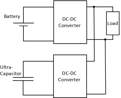
2.2. Battery/Ultra-Capacitor Parallel Topology
[image:2.595.225.521.500.702.2]The battery/ultra-capacitor parallel topology [4], as shown in Figure 3, is con-nected with two DC-DC converters in parallel. Because the DC-DC converters can control the battery current and the load voltage, the battery high frequency current problem is solved. So the topology can increase the battery cycle life and the battery bank size can decrease.
Figure 1. Electrochemistry characteristics of energy storage devices.
Batteries
103
102
101
100
10-1
10-2
107
106
105
104
103
102
101
100
Ultracapacitors
Capacitors
Specific Power (W/Kg)
Spe
ci
fic
E
ne
rg
y
(W
h/K
DOI: 10.4236/cs.2018.99013 127 Circuits and Systems
Figure 2. Battery/Ultra-capacitor passive topology.
Figure 3. Battery/Ultra-capacitor parallel topology.
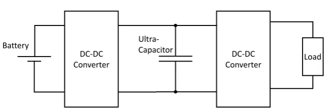
2.3. Battery/Ultra-Capacitor Series Topology
Battery/ultra-capacitor series topology [5], as shown in Figure 4, is connected with two DC-DC converters in series. The two DC-DC converters also can con-trol the battery current and the load voltage, the battery high frequency current problem is solved. Compare to the battery/ultra-capacitor parallel topology the series topology’s converter size can be smaller.
3. Proposed Control Strategy and Design
3.1. The Current Control Strategy
A new current control strategy is proposed in this paper. Because the ratio of peak power and average power in hybrid electric vehicles is 10:1 [6], battery pro-vides the average power and ultracapacitor provide the transient power. So the battery current is controlled to the load average current with a low-pass filter. In this paper, the low-pass filter is substituted by moving average. The battery cur-rent Ibat is show as (1), and the ultracapacitor current IUC is how as (2), where IL
is the load current and M is the size of moving average window.
[ ]
1 i M1[
1]
bat i L
I n I n i
M = =
=
∑
− + (1)[ ]
[ ]
[ ]
UC L bat
I n =I n I− n (2)
In HESS, the ultracapacitor’s voltage needs to be control. In this paper, use changing moving average window size between sampling point and sampling
DC-DC
Converter Load
Battery Ultra-Capacitor
DC-DC
Converter Load
Battery
Ultra-Capacitor DC-DC
[image:3.595.275.474.199.360.2]DOI: 10.4236/cs.2018.99013 128 Circuits and Systems
Figure 4. Battery/Ultra-capacitor series topology.
point to produce nonlinear dc current that can use to charge the ultracapacitor. The nonlinear dc current derivations are shown in (3) and (4).
[
1]
1{
[
2]
[
3]
[ ]
[
1]
}
bat L L L L
I n I n M I n M I n I n
M
+ = − + + − + +…+ + + (3)
[
1]
1{
[
1]
[
2]
[
1]
}
1
bat L L L
I n I n M I n M I n
M
+ + = − + + − + +…+ +
+ (4)
The Equation (3) is the battery current at (n + 1) sampling point without changing the window size, the Equation (4) is battery current which change the window size. Comparing (3) and (4), the differential current diff n+
[
+1]
is shown as (5). In this paper, use the difference current to charge the ultracapaci-tor, and control the ultracapacitor in a range.
[
1]
[
1]
[
1]
1[
1]
1
bat bat L
diff n I n I n I n M
M
+ + = + + − + ≅ ⋅ − +
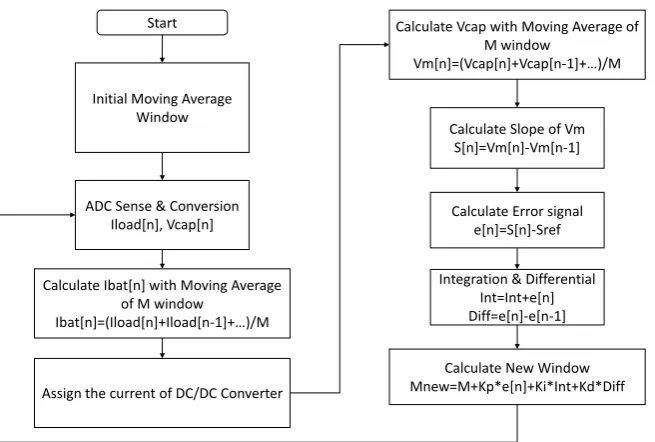
+ (5) The Hybrid Energy storage system is implement in digital circuit so the HESS control software flow chart is shown in Figure 5. For performance evaluation, the ultracapacitor utilization is defined in (6), where Prms cap, is the root mean square of power disspation in untracapacitor and Prms bat, is the root mean square of power disspation in battery.
, capacitor
, ,
rms cap
rms cap rms bat P
U
P P
=
+ (6)
3.2. Design of DC/DC Converter
A small-signal transfer function for PWM DC-DC converter is needed to under-stand the converter performance and control. Since we have to control the input current of the converter which is also equal to the inductor current, transfer function between duty cycle and inductor current needs to be determined.
The boost converter can be modeled with a circuit averaging technique [7], as shown in Figure 6. For a CCM boost converter, the currrent through the switching transistor is shown in (7), where (D + d) is the duty cycle and IL+il
is the inductor current, and the voltage of diode is shown in (8), where VO+vo
is the output voltage.
(
)(
)
S L l
i = D d I+ +i (7)
(
)(
)
D O o
v = D d V+ +v (8) DC-DC
Converter Load
Battery Ultra-Capacitor
DOI: 10.4236/cs.2018.99013 129 Circuits and Systems
[image:5.595.215.536.326.429.2]Figure 5. Flow chart of the proposed HESS current control strategy.
Figure 6. The small-signal model of CCM boost converter.
For Z1=sL r+ , Z2 =1 sC r+ c, and r r r Dr= + +s L DS+ −
(
1 D R)
F , we canderive the transfer function of the duty cycle to inductor current for CCM boost converter as (9).
( )
( )
( )
(
)
(
)
2(
)
22 1 1
O
C O O
l C O O
id
C
I s
C r I V i s r I V
G s
d s L r r D D
s s L LC + + + = = + − − + + (9)
4. Experimental Results
Figure 7 shows proposed hybrid energy storage system circuit, we verify devel-oped the system based on a DSP controller. The DSP device is Texas Instrument DSP320F2812, and we used it with its function such as 12 bit resolution ADC, high speed PWM module and high speed computation ability for type-III com-pensation. The PWM signals generated by the DSP controller are applied at a low-side driver to drive the MOSFET switching. The current sharing of battery and ultracapacitor algorithm is also build with DSP controller.
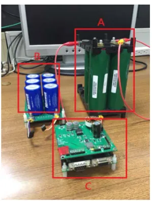
Figure 8 shows the physical setup of HESS system, where the part A is the Start
Initial Moving Average Window
ADC Sense & Conversion Iload[n], Vcap[n]
Calculate Ibat[n] with Moving Average of M window
Ibat[n]=(Iload[n]+Iload[n-1]+…)/M
Assign the current of DC/DC Converter
Calculate Vcap with Moving Average of M window
Vm[n]=(Vcap[n]+Vcap[n-1]+…)/M
Calculate Slope of Vm S[n]=Vm[n]-Vm[n-1]
Calculate Error signal e[n]=S[n]-Sref
Integration & Differential Int=Int+e[n] Diff=e[n]-e[n-1]
Calculate New Window Mnew=M+Kp*e[n]+Ki*Int+Kd*Diff + - - + Load Io dVO Dvo
Dil dIL C
-DOI: 10.4236/cs.2018.99013 130 Circuits and Systems
[image:6.595.299.449.238.436.2]Figure 7. The circuit implementation of HESS controller.
Figure 8. The experimental setup of HESS.
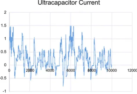
lithium battery module, the part B is the ultracapacitor module, and the part C is the control circuit module. The experimental current waveforms are shown in Figure 9 and Figure 10. Figure 9 shows the battery current and Figure 10 shows the ultracapacitor current. We can see the battery current change is flat and the proposed control strategy can improve 3% - 4% ultracapacitor utiliza-tion.
5. Conclusion
DOI: 10.4236/cs.2018.99013 131 Circuits and Systems
Figure 9. The battery current waveform of HESS.
Figure 10. The ultracapacitor current waveform of HESS.
new control strategy. The proposed control strategy can improve the system performance and ultracapacitor utilization, while also decreasing the battery pack size to avoid the thermal runaway problems and increase the life of the battery. The experiment results show the proposed control strategy can improve 14% ultracapacitor utilization.
Acknowledgements
The authors would like to thank the editor and the referee for their comments. This work was supported in part by the Ministry of Science and Technology, Taiwan, under Grant No. 106-2221-E-009-014.
References
[1] Duryea, S., Islam, S. and Lawrance, W. (2001) A Battery Management System for Stand-Alone Photovoltaic Energy Systems. IEEE Industry Applications Magazine, 7, 67-72. https://doi.org/10.1109/2943.922452
[image:7.595.254.491.277.440.2]DOI: 10.4236/cs.2018.99013 132 Circuits and Systems
977-980. https://doi.org/10.1126/science.1122152
[3] Hsieh, Y.C., Moo, C.S., Tsai, T.J. and Ng, K.S. (2011) High-Frequency Discharging Characteristics of LiFePO4 Battery. IEEE Conference on Industrial Electronics and Applications, Beijing, 21-23 June 2011, 953-957.
[4] Cao, J. and Emadi, A. (2012) A New Battery/Ultra-Capacitor Hybrid Energy Storage System for Electric, Hybrid and Plug-In Hybrid Electric Vehicles. IEEE Transac-tions on Power Electronics, 27, 122-132.
https://doi.org/10.1109/TPEL.2011.2151206
[5] Onar, O. and Khaligh, A. (2008) Dynamic Modeling and Control of a Cascaded Ac-tive Battery/Ultra-Capacitor Based Vehicular Power System. IEEE Vehicle Power and Propulsion Conference, Harbin China, 3-5 September 2008.
[6] Zhang, Y., Jiang, Z. and Yu, X. (2008) Control Strategies for Battery/Supercapacitor Hybrid Energy Storage Systems. IEEE Energy 2030 Conference, Atlanta, GA, 17-18 November 2008. https://doi.org/10.1109/ENERGY.2008.4781031