A Distributed Event System for Use in Mobile Environments
Peter Barron BAI, BA
Department of Computer Science,
Trinity College, Dublin.
A dissertation submitted to the University of Dublin,
in partial fulfilment of the requirements for the degree of
Master of Science in Computer Science
Declaration
I, the undersigned, declare that the work described in this dissertation is, except where otherwise stated, entirely my own work and has not been submitted as an exercise for a degree at this or any other university.
Signed: ___________________ Peter Barron September 1999
Permission to lend and/or copy
I, the undersigned, agree that Trinity College Library may lend and/or copy this dissertation upon request.
Abstract
Recent research into the automation of certain tasks within buildings has been shown to provide a better working environment and also has the potential to make buildings more responsive to the needs of the community at large. The name "smart building" is usually applied to such settings. Such an experimental environment is planned for the O’Reilly Institute, Trinity College Dublin. Examples of services that could be provided, include forwarding of calls and e-mail, automatic door opening for people who have been given access permission, management of heating/lighting and tailoring information delivery to the users current context/location.
It is envisioned that people within the building will carry a hand held device, which will be their point of access to the building. Using the hand held device, users would be able to access the different services around the O’Reilly building. The services that the users can access will depend on where they are located, and what rights they have to that service. Examples may include printer and terminal access rights.
Acknowledgements
Contents
1. INTRODUCTION... 1
1.1 MOTIVATION... 1
1.2 OBJECTIVES... 1
1.3 ROADMAP... 2
2. EVENT SERVICES... 3
2.1 INTRODUCTION... 3
2.2 CORBA’S EVENT SERVICE... 3
2.2.1 CORBA EVENT MODEL... 3
2.2.2 SUMMARY... 4
2.3 ECO ... 4
2.3.1 OVERVIEW OF THE ECO MODEL... 5
2.3.2 ECO API ... 5
2.3.3 SUMMARY... 6
2.4 JEDI ... 6
2.4.1 OVERVIEW OF JEDI ARCHITECTURE... 6
2.4.2 EVENT DISPATCHER... 7
2.4.3 MOBILITY... 8
2.4.4 SUMMARY... 8
2.5 SIENA... 8
2.5.1 OVERVIEW OF SIENA EVENT SERVICE... 8
2.5.2 FILTERS AND PATTERNS... 9
2.5.3 MOBILITY... 10
2.5.4 OPERATION BEHAVIOUR... 10
2.5.5 SERVER TOPOLOGIES... 10
2.5.6 SUMMARY... 11
2.6 CAMBRIDGE EVENT MODEL... 11
2.6.1 OVERVIEW OF MODEL... 12
2.6.2 FILTERS... ... 12
2.6.3 COMPOSITE EVENTS... 12
2.6.4 SUMMARY... 13
2.7 JAVABEANS... 13
2.7.1 ARCHITECTURE... 13
2.7.2 SUMMARY... 14
2.8 SUMMARY OF EVENT SERVICES... 14
3. WORKING ENVIRONMENT ... 16
3.2 SMART BUILDING... 16
3.3 MOBILE ENVIRONMENT... 16
3.4 POLICY SERVER... 16
3.4 SUMMARY... 17
4. DESIGN ... 18
4.1 INTRODUCTION... 18
4.2 EVENT SERVICE REQUIREMENTS... 18
4.3 OVERVIEW OF DESIGN... 19
4.4 DESIGN OF EVENT SERVICE... 19
4.4.1 MAIN COMPONENTS OF SERVICE... 19
4.4.2 EVENTS... 20
4.4.3 EVENT SERVICE OPERATIONS... 20
4.4.4 CONTROL EVENTS... 24
4.4.5 FILTERS... ... 25
4.4.6 MOBILITY... 25
4.4.7 EVENT NAMING SERVICE... 27
4.5 SUMMARY... 29
5. IMPLEMENATION ... 30
5.1 INTRODUCTION... 30
5.2 EVENT BUS... 31
5.3 SINK... 34
5.4 SOURCE... 35
5.5 FILTERS... ... 36
5.6 EVENTS... 36
5.7 EVENT NAMING SERVICE... 37
5.8 SUMMARY... 38
6. EXPERIMENTS AND EVALUATION... 39
6.1 INTRODUCTION... 39
6.2 EFFECTIVENESS OF FILTERS... 39
6.2.1 ACTIVE BADGE SYSTEM... 39
6.2.2 EXPERIMENT SET-UP... 39
6.2.3 RESULTS... 41
6.3 PERFORMANCE... 42
6.3.1 SUBSCRIBING... 42
6.3.2 UNSUBSCRIBING... 42
6.3.3 ADVERTISING... 43
6.3.4 UNADVERTISING... 43
6.4 EVALUATION OF EVENT SERVICE... 44
7. CONCLUSION ... 45
7.1 DISSERTATION REVIEW... 45
7.2 ACHIEVEMENTS... 45
7.3 FUTURE DEVELOPMENTS... 46
7.4 CONCLUDING REMARKS... 46
BIBLIOGRAPHY ... 47
APPENDIX A – EVENT SERVICE IDL FILE ... 49
APPENDIX B – EXAMPLE CLASSES FOR A TYPE EVENT ... 51
B.1 PETEREVENTSINKLISTENER... 51
B.2 PETEREVENTSINK... 51
B.3 PETEREVENTSOURCE... 52
List of Figures
FIGURE 1 EVENT CHANNEL... 4
FIGURE 2 A LOGICAL VIEW OF JEDI ARCHITECTURE... 6
FIGURE 3 STRUCTURE OF DISTRIBUTED EVENT DISPATCHER (DS). ... 7
FIGURE 4 HIGH LEVEL VIEW OF THE SIENA ARCHITECTURE... 9
FIGURE 5 EXAMPLE OF AN EVENT FILTER... 9
FIGURE 6 EXAMPLE OF A PATTERN OF EVENTS... 10
FIGURE 7 SIENA SERVER TOPOLOGIES. ... 11
FIGURE 8 OVERVIEW OF JAVABEANS EVENT MODEL... 13
FIGURE 9 MAIN COMPONENTS... 20
FIGURE 10 ADVERTISING AN EVENT... 21
FIGURE 11CLIENT SUBSCRIBING TO AN EVENT... 22
FIGURE 12 NOTIFICATION OF AN EVENT TO INTEREST PARTIES... 23
FIGURE 13 UNSUBSCRIBING FROM AN EVENT... 24
FIGURE 14 MOBILITY OF SINKS... 26
FIGURE 15 MOBILITY OF SOURCES... 27
FIGURE 16 EVENT NAMING SERVICE STRUCTURE... 28
FIGURE 17 BASIC COMPONENTS AND INTERACTIONS BETWEEN COMPONENTS... 30
FIGURE 18 EVENT DATA STRUCTURE... 32
FIGURE 19 OVERVIEW OF SINK WITHIN THE USER DOMAIN... 34
FIGURE 20 OVERVIEW OF ACTIVE BADGE SIMULATION... 40
FIGURE 21 SUBSCRIBING RESULTS... 42
FIGURE 22 UNSUSCRIBING RESULTS... 43
List of Tables
TABLE 1 RESULTS FROM GOD EXPERIMENT... 41
TABLE 2 RESULTS FROM BIG BROTHER EXPERIMENT... 41
TABLE 3 RESULT FROM THE CCTV EXPERIMENT... 41
TABLE 4 SUBSCRIBING RESULTS... 42
TABLE 5 UNSUBSCRIBING RESULTS... 43
TABLE 6 ADVERTISING AN EVENT RESULTS... 43
TABLE 7 UNADVERTISING AN EVENT RESULTS... 43
1. INTRODUCTION
1.1 Motivation
Increasing interest has been shown in the automation of certain tasks within a building, whether it is in the home or at the office. The potential to make the building more responsive to the wants and needs of the community make it an attractive and potentially useful concept. The name “smart building” or “intelligent building” is usually applied to such settings. The Intelligent Interfaces and Building (IIB) group plans such an experimental environment for the O’Reilly Institute in Trinity College Dublin. The services that an intelligent building could provide are endless, some examples could include phone messages and email being forwarded to your current location, the automatic opening of doors for people with the appropriate access permission and the setting of heating and lighting to users requirements. The list of services that could be provided by an intelligent building is unbounded, all that is needed is an imaginative mind.
People within the building will carry small hand held devices that will act as their point of access to the smart building. Such a device could be Personal Digital Assistant (PDA), which are readily available in the market place. It envisioned that people using the hand held devices would be able to access the different services around the smart building. Although this depends on the location of the person within the smart building and what permission they have to use a service. Such services can include access to certain printers and terminals.
Much work has already been developed for the infrastructure of a smart building. A Policy Service [Kunetz1999] has been developed to control the rights or permissions of users to access the different services within a smart building. A framework [GD1999] has been built to allow sensors or motors that are located on a LonWorks network access from an Ethernet network. Also, described in [WND1999] is the architecture for the mobility of objects within a mobile environment.
The purpose of this dissertation is to provide an infrastructure that will allow the different components within a smart building communicate with each other. To this aim a distributed event service will be used. The goal of this dissertation is to design and implement this distributed event service, to ensure that it will be able to cope within a smart building environment and capable of controlling the flow of events from producer to consumers.
1.2 Objectives
The overall objective of this work is to develop a distributed event service that will be able to cope with the environment outlined in the previous section and detailed in Chapter 3. This is broken down into four main sections.
• Ensure that event service that is developed within this dissertation can be integrated into the software model of the smart building and in particular support the use of the Policy Server within the service.
• Develop an event service that uses typed events and has the ability to ensure that event storming 1 does not occur.
• The last objective is to show that additional features such as filters help in the scalability of the event service.
1.3 Roadmap
Chapter 2 reviews the current event services that have developed with the research and commercial sectors. It pays particular attention to the event services that have influenced the design and implementation of the event service developed within this dissertation.
Chapter 3 explores the environment in which the event service is required to operate in.
Chapter 4 presents the design for a distributed event service that may be used within the environment introduced in Chapter 3.
The implementation of the proposed architecture is discussed in Chapter 5. Its evaluation is considered in Chapter 6.
Finally, Chapter 7 summarises the achievements of this work and possibilities for future research.
1 Event Storming is the uncontrolled notification of events to clients, who may or may not wish to receive the notification of
2. EVENT SERVICES
2.1 Introduction
In recent years event and notification services have come to the forefront as a means of increasing the potential of some user applications. These services come in many different shapes and sizes, from Graphical User Interfaces to bigger more distributed services such as the one employed by Corba’s [CORs1998] event service. This is an area of research which is ever expanding and which is now covering a cross section of computer industry. This chapter reviews the different approaches that have been used to develop these event and notification services. Two of these services have come from the commercial sector and remainder has been gathered from the research domain.
2.2 CORBA’s Event Service
The Common Object Request Broker Architecture (CORBA) event service is part of an additional group of services that have been defined by the Object Management Group (OMG) under the [CORs1998] specification. This service adds an extra dimension to the CORBA standard by adding another means for CORBA objects to communicate with each other. Instead of the normal direct invocation methods from object to object, the CORBA Event Service defines two roles for the objects: the supplier role 2 and the consumer role 3. This allows the decoupling of communication between the objects. The following sections will define the architecture for this service.
2.2.1 CORBA Event Model
Under the specification for the Event Service [CORs1998] there are two different ways of initiating event communication between suppliers and consumers. The first approach requires the supplier of the events to start the transfer of the event data to the consumers. This is known as the push model. The other method allows the consumers to request the event data from the suppliers and is known as the
pull model. In the pull model the consumer has the choice of either using a blocking or non-blocking
method for obtaining the event data. If the blocking method is used the consumer’s execution thread will be blocked until an event has been received. Alternatively, the consumer can poll the channel for events.
For the consumer to receive event data it first has to set up the connection with the supplier. The simplest method is for the consumer to swap object references with the supplier. However, to make the connection more anonymous an event channel can be used. The event channel is a CORBA service that allows multiple suppliers and consumer to communicate asynchronously with each other. The channel is a standard CORBA object and the communication is accomplished by using the normal CORBA request.
2 The supplier is responsible for the production of event data.
For suppliers and consumers to attach to the event channel a two step registration process has to be completed. The supplier or consumer must obtain a proxy from the administrator interfaces, ConsumerAdmin and SupplierAdmin, which are located on either side of the event channel. On receiving a proxy the consumer or supplier can then connect to the channel through the proxy (see fig1).
Figure 1 Event Channel
The reason for this two step approach is to allow support for composing event channels by an external agent. Such an agent could obtain the proxy supplier from one event and the proxy consumer from another and by passing the reference to the other as part of their connect operation it is possible to compose the two channels.
Communication of events can either be generic or typed. In the generic case, all the event data is passed as a single parameter through the event channel. While in the typed case, a mutually agreed interface has to be defined in the OMG IDL. Once agreed upon, the typed interfaces of the proxy and
admin objects can be defined. The typed version of the pull consumer and push supplier proxy will
only allow event requests of that particular type to be passed through to the consumer. This therefore acts as an event filter based on type.
2.2.2 Summary
The CORBA Event Service standard has defined a very generic event service that could be used in almost any type of application. There are however some drawbacks to the current specification. The major one is the limitations of filtering in the specification. Although at this point a RFP has been issued and a number of submissions 4 have been submitted to OMG.
2.3 ECO
The event model described in [SCT1995] was developed at the computer department at Trinity College Dublin. This event model was initially developed to address the distributed virtual reality that might be associated with next generation video games. The environment it was expected to work in, was one where a single source may disseminate information to a number of destinations. The model was also expected to support real-time applications as well as more large-scale applications with thousands of objects.
4 [TIHP1998] and [BDEF+1998]
Event Channel
ConsumerAdmin SupplierAdmin
Consumers
Supplier Proxy Supplier Proxy
Consumer Proxy Consumer Proxy
2.3.1 Overview of the ECO model
The abbreviation ECO stands for the three main central concepts of this model: Events, Constraints and Objects. Within the ECO environment everything is described as an object. Each object is an instance of a class, which has instance variables and a number of methods that act on these variables. These objects communicate by announcing events and by processing these events. An ECO object is able to announce or receive any number of different events. The event is the means by which the ECO objects can communicate. In [SCT1995] the event is defined as a typed event.
Constraints are a mechanism by which the ECO model can control the propagation of events. It accomplishes this by specifying a condition that must be fulfilled before the event can be passed on. Within this model there are three different types of constraints Notify, Pre and Post.
Notify Constraints
The notify constraint is an option provided by the destination object to help in control the propagation of events. When an ECO object subscribes to an event it can specify the conditions (constraints) to be fulfilled before the event is forwarded to the subscribing object. The only data that the conditions may use are those that are contained in the parameters of the event.
Pre and Post Constrains
The Pre and Post constraints are attached to the method/event bindings of the ECO object. These constraints are executed locally as they require access to object instance variables. They are used to implement synchronisation within the objects, as well as controlling the concurrency level and timing control.
2.3.2 ECO
API
The API for the ECO is based on three operations that allow the ECO objects to receive and send events. The subscribe operation is used by the ECO object to show its interest in a particular event. It is of the form,
Subscribe MethodName(EventName,NotifyName,PreName,PostName);
The MethodName is local to the object that invokes the subscription and the EventName is the name of the event that the object wishes to subscribe to. The last three parameters are constraints, which are an optional extra. For the ECO object to subscribe to the event, it first must be declare in its inevent list. For an ECO object to raise an event it uses the announce operation to notify the ECO objects that are interested in the event. It is of the form,
Announce EventName(parameters);
The EventName must be located in the outevent list for the ECO object to raise the event. The operation is asynchronous, so it is not necessary for the ECO object to wait for the event to be sent.
The unsubscribe operation is used by the ECO objects to unregister there interest in a particular event. It is of the form,
As in the subscribe operation the MethodName is the local object which invokes the unsubscribe operation. The EventName is the event that the ECO object wishes to unregister from.
2.3.3 Summary
In summary the ECO model is based around it’s three main concepts of events, constraints and objects. The events are the glue between the objects and provide a means for communication, while the constraints ensure that the propagated events only get to the ECO objects that wish to receive then. In many ways notification constraint acts as an event filter for the model. As far as it is known this model has been implemented three times 5 with varying degrees of completion.
2.4 JEDI
The JEDI (Java Event-based Distributed Infrastructure) is an event-based, object-orientated infrastructure that been developed by CEFRIEL – Politecnico di Milano in Italy. The JEDI architecture has been used in implementing a network-wide Process Support System called OPSS 6. The JEDI model is described in [CNF1998a] and [CNF1998b].
2.4.1 Overview of JEDI Architecture
[image:15.595.95.487.506.688.2]The JEDI infrastructure is based on active objects (AO) and event dispatchers (ED), which in conjunction provide the framework for the production and delivery of events (see fig2). Within this model AO’s are defined as autonomous entities that perform application-specific tasks. Each AO communicates with other AO’s by producing and consuming events. The delivery of events is the responsibly of the event dispatcher, which only delivers to AO’s that have shown an interest in the event. AO’s declare interest in an event by the event subscription operation and can also stop-accepting events by calling the event unsubscribe operation. The JEDI architecture ensures the notification of events is accomplished in an asynchronous way.
Figure 2 A logical view of JEDI architecture.
5 The VOID Shell [Tea1995], DECO [ODC+1196] and [MH1998]
6 ORCHESTRA Process Support System, which is describe in [CNF1998a] and [CNF1998b].
= Event
Event Dispatcher
AO AO
The JEDI architecture defines an event as a set of ordered strings. The first being the name of the event and remaining strings as the parameters of the event. An example of a JEDI event might be open(foo.c,
read), where open is the name of the event while foo.c and read are the parameters of the event. An AO
subscribing to an event has the choice of specifying a particular event, or it can specify an event pattern. The event pattern allows the AO to subscribe to events that match that particular pattern defined in the subscription operation.
2.4.2 Event
Dispatcher
The central concept of the JEDI model is the Event Dispatcher. It is responsible for the delivery of events in the right order and to support the mobility of AOs through the system. In [CNF1998b] the Event Dispatcher is described logically as being a centralised component, since the dispatcher must have global knowledge of the generation of events and the AO’s that have subscribed to events. However, the realisation of the drawbacks of a centralised component has prompted [CNF1998a] and [CNF1998b] to provide a second implementation for their model i.e. a distributed version.
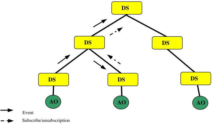
[image:16.595.90.465.391.602.2]The distributed version of the Event Dispatcher creates a set of Dispatcher Servers (DS) which are interconnected in a tree like structure. Each DS is located on a different node and is connected to one parent DS, unless it is the root, and to zero or more descendants. The AO’s are connected to the structure via the DS’s (see fig3).
Figure 3 Structure of distributed event dispatcher (DS).
The Dispatcher Server employs a hierarchical strategy for the distribution of events, subscribing and unsubscription messages. In this strategy, all subscription request are propagated upwards in the tree. Each DS that receives a subscribe or unsubscription request, accepts it and makes an entry for the AO. On an AO producing an event it is passed to the local DS where it is forwarded up the tree. On receipt of an event the DS checks it descendants and passes the event onto any descendant that has requested the event. It then forwards the event to its parent DS. This strategy ensures that events and subscriptions get to all the relevant nodes.
DS
DS DS
DS DS
DS
Event
Subscribe/unsubscription
AO
2.4.3 Mobility
Under the JEDI architecture mobility of active objects are supported through the use of reactive
objects. A reactive object defines an abstract method called processMessage that has to be specified by
the programmer and is automatically invoked each time the reactive object receives an event. This object can autonomously decide to move to a different host. On doing so, it invokes the move method and causes the following series of events to occur:
• The reactive object disconnects from the ED and the thread of execution controlling the reactive object is stopped.
• The reactive object is serialised using the Java facilities.
• The reactive object is them moved to it new destination, where it reconnects to the ED. • The ED on request from the reactive object stores the events until the object has moved
location successfully when it then forwards the stored events to the reactive object.
2.4.4 Summary
The JEDI model provides a very useful infrastructure for the distribution of events and the mobility of objects through a network. However this model does not supply any methods for the filtering of events. Also the defining of events as a set of strings limits the parameters that can be defined for an event. It might be more appropriate if the events where defined as Java objects instead of strings. While the approach of a hierarchical topology has been proven to be quite a successful method for many distributed applications, in the case of the distributed version of the JEDI model it could prove to be its weak spot. Due the fact that all messages are being forwarded to the root of the DS tree, which might cause the overloading of the higher-level servers.
2.5 Siena
Siena (Scalable Internet Event Notification Architectures) is a wide-area event notification service that has been developed as a PhD thesis [Car1998] in Politecnico Milano. This thesis is an extensive study into the support of event-based application on wide-area networks, in the process it describes in detail the event service Siena.
2.5.1 Overview of Siena Event Service
Within the Siena infrastructure there are two types of parties/objects defined: object of interest and
interested party. Objects of interest are producers of events that can specify events they intend to
Figure 4 High level view of the Siena architecture.
The Siena event service specifies five different operations that it exports from the event service. The first three: publish, subscribe and unsubscribe are quite common to most event services. The last two: advertise and unadvertise are quite new in the event or notification service scene. The advertise operation is invoked by an object of interest to indicate that it intends to produce events of a certain type. Unadvertise operation has the opposite effect to the advertise operation, it indicates to the event service that the object of interest no longer wishes to produce such an event. The advertise operation is used to introduce more information into the event service so that it can help route subscriptions and notifications more efficiently.
To identify the different parties/objects within the infrastructure, Siena uses a generic URI naming scheme. This shows the location of the object and what protocol is needed for the event service to communicate with that object. Any notification of this event is done through the naming scheme.
2.5.2 Filters and Patterns
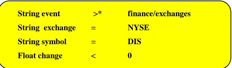
Siena describes an event as a set of attributes, each of which is uniquely identified by its name. The attributes of an event can only be defined as char, integer, boolean, float, string, byte-array, and date. This is quite a limited set of types compared to other event services. The Event filters in this service are made from a set of attribute filters. Each attribute filter specifies a name, a type, a boolean binary operator and the value for the attribute. In the example show in figure 5, the filter will only select the set of events that come from NYSE exchange and where the change is negative.
Figure 5 Example of an Event Filter
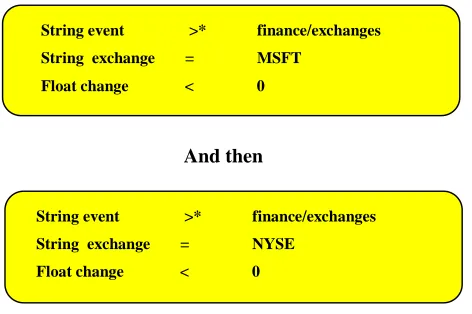
The Siena infrastructure extends the idea of event filters by using combinators 7 to create patterns.
While event filters will select one class of events at a time, a pattern can select several events that together match an algebraic combination of filters. An example of a pattern can be seen in figure 6.
7 Combinators are algebraic expressions that combine event filters together to create patterns.
Event Service
Object of interest Interest party
Advertise
Publish
Subscribe
Notify
String event >* finance/exchanges String exchange = NYSE
[image:18.595.192.420.575.642.2]Figure 6 Example of a pattern of events
2.5.3 Mobility
While Siena does not support code mobility directly, it does define two ways in which mobility might be possible with the Siena framework. The first approach, which the Siena architecture calls
transparent, uses network-level mechanisms to manage the mobility of objects through the system. The
second approach relies on adding an extended layer between the event service and the mobile object to manage the movement of objects. The Siena infrastructure calls this approach external.
2.5.4 Operation Behaviour
In [Car1998] two different behaviours for the event have been described: subscription-based and
advertisement-based. The reasons for [Car1998] defining the two implementations is to find the most
appropriate solution for a flexible, more scalable event service.
In the subscription-based event service only subscriptions determine the semantics of the service. Advertisements can be used to optimise the routing of subscriptions, but are not necessary. The event service will guarantee delivery of events only if the interested party has subscribed to that event. This implies that, unless an event has been notified before the interested party has subscribed, it does not receive the event notification.
While in the advertise-based event service both subscription and advertisement are used. The semantics of this service will only guarantee the delivery of event notifications if objects of interest have advertised an event and that interested parties have subscribed to the event after the event has been advertised. This implies that, if an object of interest receives a subscription before it advertises the event, it can not guarantee the notification of an event.
2.5.5 Server
Topologies
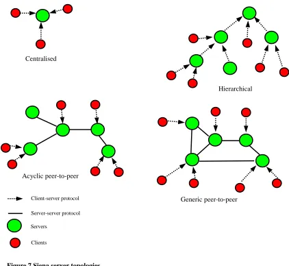
[Car1998] defines four different server topologies: centralised, hierarchical, acyclic peer-to-peer and
generic peer-to-peer (see figure 7). The Siena event service was implemented using each of topologies
and was tested for the flexibility and scalability of the service. [Car1998] found that the distributed topologies outperformed the centralised approach, when the number of objects of interest and
String event >* finance/exchanges String exchange = MSFT
Float change < 0
String event >* finance/exchanges String exchange = NYSE
Float change < 0
interested parties increased. Of the distributed topologies the acyclic peer-to-peer did a better job in distributing the load over all the event servers.
Figure 7 Siena server topologies.
2.5.6 Summary
[Car1998] has provided extensive research into providing a scalable wide-area event notification service. It has studied in detail the best approaches for distributing Event Servers and has found that the acyclic topology provides the best results. The Siena event service also aids clients to control the receiving of event notifications by the use of filters and patterns. There are some disadvantages to the Siena event service, the main one being that there are a limited number of parameter types that it allows the event notification to pass. The Siena infrastructure does not directly support the mobility of objects.
2.6 Cambridge Event Model
The Cambridge Event Model was developed in the computer laboratory of the University of Cambridge and is described in [BBHM1995]. This model, as in other event services discussed above, relies on clients subscribing to the events. What makes this service different is the ability of the infrastructure to compress the events by using a composite event server.
Centralised
Hierarchical
Generic peer-to-peer Acyclic peer-to-peer
Client-server protocol Server-server protocol Servers
2.6.1 Overview of Model
Through the extension of Interface Definition Language (IDL) the Cambridge event model has been able to create a strongly typed event service. This enables servers to be more specific in the parameters it wishes to declare in an event. It also allows clients to see the server’s specification of the event and enables the client to be selective in the events it wishes to receive notification of. An example from [BBHM1995] shows an IDL declaration of a seen event object.
Badge : INTERFACE =
Seen: EVENTCLASS [badge : BadgeId; sensor: SensorId]; END.
The above event declaration is part of the Active Badge System that was developed by the University of Cambridge. The system monitors the location of badge wears throughout the complex. A Seen event is raised by the Badge System every time a badge wearer passes by a badge sensor.
The communication between servers and clients is based on three generic operations: registration,
signalling and notification. For client to register an interest in the event it is required to invoke the
registration operation and supply an event template. The event template is used pass the parameters that specify the events of interest. The signal operation enables the services to detect occurrences as event instances. Notifications of events are instigated by the notification operation and as with other event services the clients will receive notification of events if they have registered an interest.
2.6.2 Filters
Filters in the Cambridge model are specified at the time the client registers an interest in an event. At this stage the client defines a filter expression which indicates to the event service what events it wants notification on. The filter is defined through event template, where specific values are given to the parameters. These values must match the event before notification of a client can proceed. Wild cards are also used to indicate that any value is acceptable for this parameter. [BBHM1995] uses the Seen event to supply an example of a filter expression.
Seen (13,R)
The above example will only allow the client to be notified when any badge sensor in the complex has seen badge 13. This particular filter would allow the Active Badge System to track a badge through the building. In the following example the client will be notified of every badge that has been seen at sensor 23. In the Active Badge System this could be useful in tracking badges that have entered a particular zone.
Seen (P, 23)
2.6.3 Composite Events
or more particular events on there own but are when they occur in a certain way, to receive a single event. The infrastructure for composition of the events is based on the finite machine, which has been enhanced to allow multiple tokens to be active within the machine at any one time.
2.6.4 Summary
The Cambridge Model in many respects is similar to event services described above, except for the additional feature for the composition of events. This is a powerful tool in controlling the flow of events to clients. The Cambridge Event model has been used to implement a number of event services such as the Active Badge System discussed above and in [BBHM1995].
2.7 JavaBeans
JavaBeans [Sun1997] is a component architecture developed by Sun. It is part of suits of packages that have been developed for use in programming in Java. As part of JavaBeans architecture there is a specification for an event model. This model was designed for more centralised systems, thought it is possible to extend service into a more distributed service.
2.7.1 Architecture
The JavaBeans infrastructure defines two roles for the participants in the model, consumers of events whom are know as listeners and suppliers of events that are called sources. Their roles are defined in two java interfaces included in Sun’s Java Development Kit.
java.util.EventObject java.util.EventListener
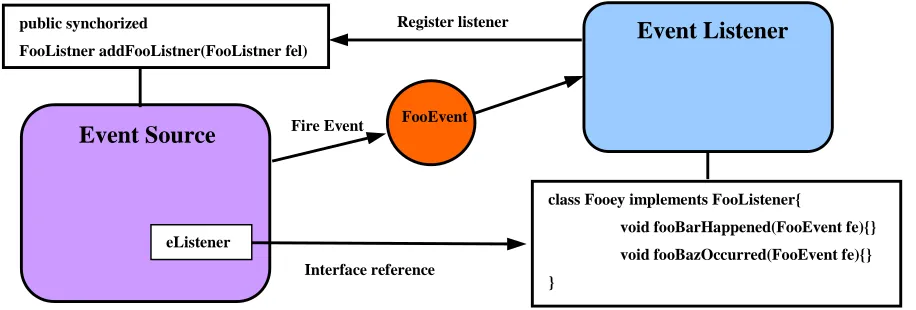
[image:22.595.89.547.525.680.2]Listener objects that wish to receive notification of events most first implement the event listener interface. They then have to identify themselves to the source by invoking the add<ListenerType> method on the event object. Once the listener has registered, the source is able to notify the listener of new events by invoking the associated method on the listener object (see figure 8).
Figure 8 Overview of JavaBeans Event Model
The delivery of the events to the listener object is synchronous, which implies that some performance penalties are associated with this implementation.
public synchorized
FooListner addFooListner(FooListner fel)
class Fooey implements FooListener{
void fooBarHappened(FooEvent fe){} void fooBazOccurred(FooEvent fe){} }
eListener
Event Source
Event Listener
FooEvent Fire Event
Interface reference
The JavaBeans event model has defined an event adaptor class. This class is an intermediary between the source and the listener objects and acts to decouple the two parties. The purpose of this class is to allow additional behaviour to be added to the JavaBeans Event Model. Examples of the uses of such adapters includes filters, buffering of events, demultiplexing multiple event sources onto a single event listener or acting as a generic-wiring manager.
2.7.2 Summary
The inability for the JavaBeans Event model to support asynchronous delivery of events or a direct implementation for the distribution of events outside a single process lead to the conclusion that this service was principally designed as a centralised event service. Also the inability of the service to support event filtering directly helps form the opinion that this event model only supplies the bare minimum for an event service to work. However it might be possible to extend the functionally of this service through the use of the event adapter class.
2.8 Summary of Event Services
In this chapter we have reviewed several event services and have covered some of the main fundamentals that are in use in event services at present. There are other event services such as COBEA [MB1998], Jini’s distributed event service [Sun1999a] or Java Spaces [Sun1999b] that have not been covered in this chapter but do offer other methods in developing event services. In the event services that are discussed in this chapter there are many different approaches: to notification of events, how events are defined and how events are subscribed to.
The definition of events fall into two main categories, those of which have typed parameters and those event services that prefer having a more generic parameter. In a general a typed event service is preferred for ease of programming and correctness. Of the event services reviewed at in this chapter the Cambridge Event Model [BBHM1995] and Seine [Car1998] uses typed events while JEDI [CNF1998b] uses a more generic event in the use of strings to define events.
In most of event services the client is required to show an interested in an event(s). For the event services discussed in this chapter, such as Seine [Car1998] or ECO [SCT1995], they use a subscribe operation. The operation indicates what events they wish to receive and other such information as filters. However in the CORBA Event Service instead of subscribing to an event(s) the client attaches itself to a channel on which events are broadcast.
In the search to try and reduce the number of notifications to clients and hence help increase the scalability, event services have developed filters. These filters allow clients to specify in more detail the events that they wish to be notified about and therefore reduce the number of notifications that the event service needs to make to clients. ECO [SCT1995], Siene [Car1998] and the Cambridge Event Model [BBHM1995] all have developed filters in various degrees of efficiently. Siene has also extended the filters to form patterns, these patterns are a combination of filters combined together. To increase the scalability, both Siene and JEDI have developed methods for routing messages through their servers. JEDI has structured its servers in a hierarchical topology. Siene has tested a number of server topologies and routing of messages. It has found that Acyclic peer-to-peer server structure gives the best load balance through the servers.
In distributed systems the mobility of objects through a system has become more desirable. It therefore makes sense that event services are able to support mobility and ensure that when objects move location that no events are lost and events are forwarded to the new location. The JEDI architecture is the only event service discussed in this chapter that supports mobility directly.
3. WORKING ENVIRONMENT
3.1 Introduction
Recent research into the automation of certain tasks within a typical building has shown to provide a better working environment. The name “smart building” is usually associated to such a setting. The Intelligent interfaces and Buildings group from Trinity College Dublin has been developing such a building. It is envisioned that the event service developed by this project will provided the glue to being the different parts of this smart building together. The rest of this chapter will develop in more depth the type of environment and other services the event service is expected to interact with.
3.2 Smart Building
It is envisioned that people within the smart building will carry a hand held device, which will act as their point of access to the building. Using the hand held device users would be able to gain access to different services around such a building. Permission to use the services depends on the location of the user and what rights the user has to the service. The Policy Server handles these user rights and will be dealt with later in this chapter. Such services could include: the automatic opening of doors to authorised users, setting your office environment such as lights and air conditioning, receiving mail and printing of documents on the nearest available printers. The event service, discussed later in Chapter 4, will be used as the means of communication between the users of the building and services that it provides.
At present the Intelligent Interfaces and Buildings group from Trinity College Dublin has developed a framework for which devices such as controllers to open door or sensors to detect users, connect into the smart building. The infrastructure uses a LonWorks network to connect the devices together and has developed a protocol bridge that connects the LonWorks network to an Ethernet network. The above infrastructure is discussed in [GD1999].
3.3 Mobile Environment
It is envisioned that the environment the event service is expected to work in will have a high instance of mobility within the system from mobile devices such as Personal Digital Assistant (PDA). The smart building project has adopted the architecture described in [WND1999]. It is therefor necessary to ensure the design of the event service be able to cope with mobility.
3.4 Policy Server
The Event Service will be an integral part in providing the communication between the users and services within the building. It necessary that the event service can gains access to the information that the Policy Server holds. This ensures that the event service dose not give access to a service that the users do not have permission for.
3.4 Summary
4. DESIGN
4.1 Introduction
It is the aim of this chapter to present a design for a distributed event service that will complement the inherent mobility of objects through a smart building and also to engage the support of the Policy Server to control access of users to the services within the building. All of which have been set out in Chapter 3. Although the event service is designed with the environment discussed above in mind, the sections below will attempt to implement a design that can be used it other situations other than a smart building environment. In Chapter 2 several event services were reviewed in detail. It is hoped that some of the features that were discussed, such as filters may integrate into the design of this event service
4.2 Event Service Requirements
As this event service will be part of the environment discussed in Chapter 3 it will be necessary that the event service described later in this chapter be able to cope with any situation that may occur within that environment. To be more specific the event service will need to be able to cope with the following:
• Mobility of objects from one location to another.
• Integrating the use of Policy Server into the event service to control access to the different services located in the smart building.
The event service is also required to support the use of filters, which will generally reduce the number of events and help with the scalability of the service. It will also help control the user access to the different service by blocking any communication with the user and as such is an important part to implementing the polices held by the Policy Server. Other requirements for the event service are as follows:
• A strongly typed Event Service that will allow a large range of parameters types to be passed through the event service.
• The event service is also required to ensure the event notifications are delivered at least once to each object that has subscribed to the event.
• The ability of the event service to scale at a reasonable rate. One of the problems, which the event service will have to overcome, is event storming8.
• Also the event service needs to delivery the events in the order that they occurred at the node which the event originated from.
• Asynchronous communication of events.
8 Event Storming is the uncontrolled notification of events to clients, who may or may not wish to receive the notification of
4.3 Overview of Design
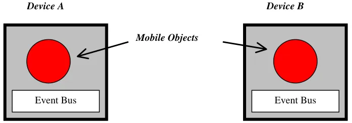
Before entering into the details of the design, it will be helpful to clarify some of the terms that will used to explain the design. A device is considered to be any object that is able to execute pieces of code and has access to the network, whether it is connected to a wireless network or a more conventional LAN. Such a device could be a PC, laptop or even PalmPilot. Mobile objects are equivalent to the Active Objects (AO) in the JEDI [CNF1998a] [CNF1998b] event model. These are defined as autonomous computational units performing application-specific tasks. Sources are objects that produce events while sinks are objects within the event service that consume events produced by sources.
The event service that will be developed later is modelled on an advertised subscription based event service. It is somewhat similar to a mode Siene [Car1998] uses in its event service. As discussed in Chapter 2, there are two basic models for the delivery of events by event services to clients. The first model requires the producer of events to distribute events to interested parties. This is known as the push model. The second model requires interested parties to poll the producer of events and is known as the pull model. For the design of this event service a push model will be used to notify interested parties. To enable controlled notification of events, filters will be used to narrow the scope of the notifications to interest parties. The decision whether to send the event is obtained by the filter executing some code on the parameters of the event, the username of the client and the type of device the client is using. Due to the environment that the event service will be operating in, it will be necessary that the event service will be able to cope with the mobility of source and sinks through the system. The approach taken is quite similar to that of JEDI [CNF1998a] [CNF1998b].
4.4 Design of Event Service
4.4.1 Main Components of Service
The main components of this architecture are the devices and mobile objects that occupy it. These devices support mobility of mobile objects from one device to another. The architecture for the mobility of these objects is covered under [WND1999]. These devices will need to support mobile objects in the producing and the consuming of the events. The event bus will support this. The event
bus is not unlike the Event Dispatcher described in the JEDI [CNF1998a] [CNF1998b] event model.
However, in this model an event bus will be located on each device. Its role is to support mobile objects in the location of events, subscription to events, notification of events and the delivery of the events. Also, its role will be to support mobile objects in moving location and insuring that the mobile objects still receive the notifications of the events that they have subscribed to.
location for a particular event. To support this the event naming service would need to keep multiple entries for each event and on request to supply the whereabouts of all the source of that event.
[image:29.595.111.460.207.329.2]The purpose of the Policy service is to hold the rights and the wishes for each mobile object within the smart building environment. The event service uses this service to create filters for the notification of events to the mobile objects. The design of the Policy service is covered under [Kunetz1999]. The Web Server is used as a storage place or library for the event buses to find class definitions of specific filters.
Figure 9 Main Components
4.4.2 Events
As part of the requirements set out in section 4.2 events are required to have a typed interface. To this aim, any object may be a parameter of an event and can be passed through the event service once it can be serialized and saved using the standard Java facilities. Care must be taken as to the size of the objects being passed as parameters as this can effect the performance of the service.
In order for interested parties to find and show interest in the different events that occur within the system, a naming system must be adopted whereby the events can be uniquely identified throughout the system. For this a domain name type-naming scheme will be used for the naming of the events. An example of unique name for an event is as follows:
ie.tcd.cs.ActiveBadge
The above example will give enough information for the event bus to located the Event Naming Server and query it for the location of the sources of the event and therefor show its interest in the event.
4.4.3 Event Service Operations
The operation of the event service is managed by five separate operations, excluding those for mobility. In the following section these operations will be explained in more detail.
Event Bus
Device A
Event Bus
Device B
Event Naming Service
Policy Service
Mobile ObjectsAdvertisement of Events
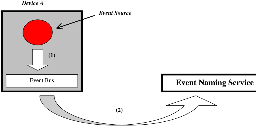
[image:30.595.96.533.155.375.2]In Siena [Car1998] sources of events have first of all to advertise their intention to publish events to the event service. The same approach will be used in this event service to indicate the readiness of the event source to produce events and also to show the location of the source.
Figure 10 advertising an event
The first step in the advertising an event is for the event source to use the Advertise(name) operation to indicate to the event bus its readiness to produce events. Advertise operation passes to the event bus the name of the event. The next step is for the local event bus to forward this information, along with location of the event source, onto the Event Naming Service specified in the name of the event. After the Naming Service receives this information for the new event, it inserts the information into its database or adds the event source to the list of other sources that are creating that particular event. Once this is completed the event source is considered to have advertised its event and the event bus is ready to receive notifications of events.
Subscribing to Event
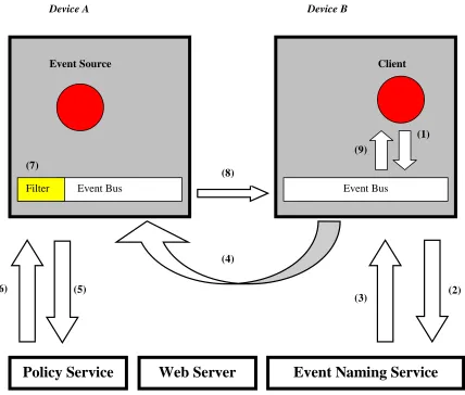
As with most event services, they require the clients in some way to subscribe to events that they are interested in. This narrows the scope of the events on the overall system. It also prevents event storming by only sending the notification of the event to the parties that have shown an interest in that event. Clients in this event service are required to subscribe to an event using the full name of the event, as described in section 4.4.2. It is also possible for the client to attach a filter when subscribing to an event, but this is not necessary on all occasions as the event bus in conjunction with the policy server can obtain one.
There are four distinct stages to subscribing; the client making the request, finding the location of the event bus(es) that are supporting the event source, subscribing to the event bus(es) and the installation of the filter. All of which can be seen in Figure 11. In the first stage (figure 11 step 1) the sink requests its local event bus to subscribe the sink to a certain event by calling subscribe(name, sink location,
filter) operation. The sink passes the name of the event, the filter if there is one and also the location of
Event Naming Service
Event Bus
Device A
Event Source
(1)
the sink to the event bus. Once the sink’s event bus has received the request information, it must then locate where the sources of the event are. This is accomplished with the help of the Event Naming Service (figure 11 steps 2,3). On receiving the locations of the sources, the event bus subscribes to each one, passing on information about the sink making the request, the name of the event and the user defined filter if specified (figure 11 step 4).
Figure 11Client subscribing to an event
When the event bus supporting the event source receives a subscribe request, it must first install the filter associated with the sink and add it to list of parties that are interested in that particular event. There are two ways in which a filter can be obtained. Either by using the filter that was defined by the sink or by requesting information from the policy server (figure 11 steps 5,6) to enable the construction of the filter. If there are two filter definitions, one from Policy Server and the other from sink, the Policy Server filter will be chosen. As will be explained later in this chapter the filter is a serialized object. If for some reason the class definition for the filter is not available on the event bus’s local host it is possible that it can obtain it from the Web Server. On completion the sink is notified of the success or failure of the operation (figure 11 step 8,9).
(5)
Device A Device B
Event Naming Service
Policy Service
Event Bus Event Bus
Event Source Client
(1)
(3) (2)
(4)
(6)
(8) (7)
Filter
(9)
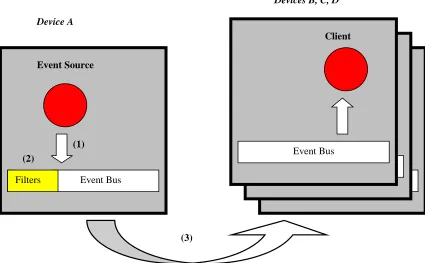
Notification of Events
[image:32.595.94.519.235.498.2]Once an event has been triggered asynchronously by a source it is necessary that the interested parties be notified of the event. It is the aim of this architecture that the interested parties receive this notification at lease once and receive the events in the order that they occurred at the source. To overcome these problems each event will be numbered in the order that they have occured at the source. When the client’s event bus receives notification of the event, it places them in the right order as they occurred. The above will only guarantee that the events from a particular source are in the right order. If there were multiple locations of the event them this architecture could not guarantee the order in which they would arrived in.
Figure 12 Notification of an event to interest parties
In normal scheme of things a typical notification might possibly look like that shown in figure 12. The event source notifies it local event bus of a new event and passes the parameters associated with this instance of the event. The job of the event bus is to then to notify the interested parties of the event. It however only notifies the mobile objects that have subscribed to the event and have passed the filter supplied by the sink or created from the policy server. The client’s event bus at appropriate time, delivery’s the event to the sink.
UnSubscribing from Events
Unsubscribing operation is the opposite of subscribing, which was defined above It is executed when sinks no longer wish to receive notification of an event. To ensure that the event bus has the right location of the event sources when unsubscribing from an event, it obtains the location of the event source from the Event Naming Service (figure 13 steps 2,3). This may not be necessary in most cases as the event sources would not have changed since subscribing to the event, but to support the mobility
Event Bus Client
Devices B, C, D
(3)
Device A
Event Bus Event Source
(1) (2)
Filters
Event Bus Client
of the event source and also the creation of new source a lookup is necessary to ensure the right location is obtained.
Figure 13 Unsubscribing from an event
Unadvertising of Events
Unadvertising operation is the opposite from a source advertising an event. This operation is called by the source to indicate to the event service that the source not longer wishes to produce events of that type. When the event bus receives the Unadvertise operation it informs the Event Naming Service that the source is no longer producing events. At this stage the source is unadvertised.
4.4.4 Control Events
Control events are events used by the event service to manage the service. In general these events are only listen to by the event buses. In the present architecture the event service defines one control event. It is produced by the Event Naming Service to indicate that there is new source of an event. Event buses are sinks to this event and they use the information provided in the event to subscribe to the new source. This occurs if they have an active sink looking for that particular event. As with other events filters can be assigned when subscribing to the event
Device A Device B
Event Naming Service
Event Bus Event Bus
Event Source Client
(1)
(3) (2)
(4) (5)
Filter
4.4.5 Filters
Filters are a concept used by many event services to control the flow of events to consumers. From Chapter 2, both Siena [Car1998] and Cambridge Event Model [BBHM1995] use filters to control flow of events. Within this architecture filters will control the flow of events to sinks, they will also be used as a means to implement the policies held by the Policy Server.
A filter is a computational piece of code that uses the parameters of the event, along with owners sink’s username and the type of device that the sink is running on to decided whether notification of the event should take place. The piece of code is predefined by the programmer and is initialised by the sink or the Policy Server. The filter can therefore transfer state to the source’s event bus, depending on how the filter is programmed to work. From the sections above it can be seen the client has the ability to specify the filter, but the event bus will use the filter from the Policy Server in preference. This is to ensure the security of the services that the client wishes to use. The filter is installed on the event bus that the source is located on. While this may well be an overhead when subscribing to an event, it means less event notifications and hence less networks traffic.
4.4.6 Mobility
As the event service is going to be located within a mobile environment it is necessary that the service is able to support mobile objects in their movement through the environment. This requires that when a sink wishes to move devices, the events that the sink has subscribed to be changed, so that the notification of events are received at the new location. If however the mobile object is a source of events, all the information associated with mobile object must be passed onto the new location of the source. The only event service from Chapter 2 that comes close to supporting mobile objects is JEDI [CNF1998a] [CNF1998b]. It defines a particular type active object that is called a reactive object. This object has the ability to support mobility. When this object decides to migrate to another device, the following occurs:
• The state of the reactive object is serialised and saved using standard Java facilities. • The reactive object moves to the new location and informs the Event Dispatcher that it is
ready to receive events.
• The Event Dispatcher keeps the events that should be received by the migration reactive object until it is ready to receive them.
It is proposed to do something similar in supporting mobility of objects within this event service. This service most able to support mobile objects that produce events and those that consume events. Therefore two separate approaches have to be taken in dealing with each case.
Mobility of Sinks
received the sink is free to move location (figure 14 steps 3-4). On arriving at its new location the sink signals to the local event bus that it is a mobile object wishing to redirect event notification to this location. The local event bus queries the Event Naming Service for the location of the sources for that event. It then requests each of the event buses supporting a source to update their records for the location of sink and forward any events that may have been buffered (figure 14 steps 5-8).
Figure 14 Mobility of Sinks
Device A Device B
Event Bus Event Bus
Event Source Sink A
(1)
(3) Filters
Event Bus Sink A
(5)
Device C
(2) (8)
Event Naming Service
(7) (6)
Mobility of Sources
[image:36.595.121.512.314.649.2]In situation where a source is moving location, it again has to call the move operation. When the event bus receives the request from the source it notifies the Event Naming Service of the intending move (figure 15 steps 1-2). The local event bus will not accept any more events from the source and is only responsible of the notification of the events that the event bus has receive prior to the move operation. The source can then move location to a new device, it does not have to wait for the event bus to send the backlog of events (figure 15 step 3). When the source has relocated to the new device it reattaches itself to the local event bus. The event bus requests from the source’s previous event bus a list of subscribing sinks and their associated filters and installs the sink information onto the local event bus (figure 15 steps 4-6). This step may not need to be initiated if there is an active source already producing the same event. The event bus then notifies the Event Naming Service of the new location of the source (figure 15 steps 7). Once the above steps has been completed the source can start generating new events.
Figure 15 Mobility of Sources
4.4.7 Event Naming Service
The Event Naming Service is an integral part of the event service. It provides the service with a means of tracking sources through the system. The tracking is achieve through event buses notifying the Event Naming Service of all sources that have advertised an event, moved location or have unadvertised an
(5) (3)
Device A Device B
Event Bus Event Source
(6) (1)
Filters
Event Naming Service
(2)
Event Source
Event Bus Filters
(4)
event. Sinks, via the event bus, are then able to query the Event Naming Service to obtain the locations of the sources when subscribing to an event. The Event Naming Service is also responsible for the production of a control event that notifies event buses of the location of new sources.
[image:37.595.77.494.259.725.2]The Event Naming Service is structured in a hierarchical topology based on the name of the event. This is to ensure that there is no one point of failure and also to help increase the scalability of the Event Naming Service. The event names are resolved using the same approach as the Domain Name Service (DNS). Static links are used by the Event Naming Service to increase performance of the service. This enables the server to bypass the normal lookup procedure and take a short cut in resolving the event name. Event buses can attach to any severs to obtain the locations of sources for an event or to update information on sources. (See figure16)
Figure 16 Event Naming Service Structure
Event Bus Device
Oxford
newmail
uk
root
newsource
ie
Cambridge
Activebadge dooropen
tcd
newmail
cs
Peterevnet dooropen
Static link
Event Bus Device
4.5 Summary
5. IMPLEMENATION
5.1 Introduction
A prototype of the event service architecture, introduced in Chapter 4, was implemented in the Java programming language and uses OrbixWeb as the basis for communication between nodes. Due to time constrains the mobility part of this service was not completed. The implementation takes full advantage the facilities that the Java programming language provides, such as exception handling, the ability of Java to serialize objects, and the strong type checking. In the implementations of the Policy Server and of other services within the smart building CORBA is used as a basis for communication. To keep the uniformity between other modules of the smart building project CORBA will also be used, which in this case is Iona’s implementation OrbixWeb.
[image:39.595.142.452.366.570.2]The event service is broken down into seven components and can be grouped into three layers (See figure 17). Two of the components, Policy Server and Class Repository, are not implemented within this project. The Class Repository will use a Web Server to dispatch class definitions. The Policy Server has already been developed under [Kunetz1999].
Figure 17 Basic components and interactions between components
The prototype of the event service is broken down into five packages. The package EventService.Bus holds the class definitions for the event bus, which includes a class, called EventBus that is used to launch the event bus. Package EventService.EventNamingService defines the classes for the Event Naming Service while the EventService.Source, EventService.Sink and EventService.Filter holds the class definitions of the super classes for the sink, source and filter. The following sections of this chapter will cover in more detail the implementation of the different components of the event service and the interaction between them.
Application
Source
Application
Sink
Event Bus
Policy Server Event Naming Service
5.2 Event Bus
The event bus is the most complex of all the components within the event service. It manages all the interactions between the sources, sinks and other components within the event service (see figure 17). It is responsible for the safe delivery of events to any sink that has subscribed to an event and is therefor an integral part of the event service. The implementation of the event bus has been taken in three sections: firstly the interaction with the sink, secondly the interactions with the source and lastly interaction with other event buses. This can easily be seen in the IDL definition for the event bus.
IDL Interface
The IDL definition for the event bus has defined three interfaces for communications with sources, sinks and other event buses. The interface defined below is used to allow sinks to subscribe and unsubscribe from events; they are equivalent operations defined in Chapter4. The autoCleanUpReg and autoCleanUpUnReg methods enable the event bus to catch sinks that crash. This will be discussed in a later section.
interface EventBusSink{
long subscribe(in string event_name,
in Sink::EventSinkCB CallBackSink, in filter_obj filter)
raises(SubscriptionException);
void unsubscribe(in string event_name, in long eventsinkid)
raises(UnsubscribeException);
boolean autoCleanUpReg(); boolean autoCleanUpUnReg();
};
The EventBusSource interface defines the advertise, unadvertise and notify operations that where introduce in Chapter 4. This interface is used by sources to show their intention to produce events and to notify sinks of new events.
interface EventBusSource{
long advertise(in string event_name)
raises(AdvertiseException);
void unadvertise(in string event_name, in long eventsourceid)
raises(UnAdvertiseException);
void notify(in string eventname,in event_obj event)
raises(NotiftyException);
boolean autoCleanUpReg(); boolean autoCleanUpUnReg();
};
interface EventsRemote{
void EBSubscribe(in string event_name,
in EventsRemote remoteeventbus, in long eventsinkid,
in filter_obj filter, in string username, in string Device)
raises(EventUnknowException);
void EBUnsubscribe(in string event_name,
in EventsRemote remoteeventbus, in long eventsinkid)
raises(EventUnknowException);
void EBNotify(in string event_name, in DestSinksIDs forwho, in event_obj event)
raises(SinkUnknowException,EBNotifyException);
};
Data Structure
A central part to the event bus is the storing and the retrieving of information about sinks and sources in an efficient manner. The information for each event is broken down into number of constituents. Each event has the EventService.Bus.eventdata class associated with the event. The class holds information about the sources and sinks ID’s and also the sequence number for the generation of events. Data on each source is kept within an EventService.Bus.sourcedata class. Sinks are broken down into two distinct groups, sinks that are local to the event bus and sinks that are remote to the event bus i.e. sinks that have subscribed to events. The information for local sinks is stored in EventService.Bus.localsinkdata class. It holds information about the callback object, username and filter that the sink is using. The EventService.Bus.remotesinkdata class holds the data relating to the remote sink such as filters, events sent to sink and the event bus supporting the sink.
[image:41.595.79.501.519.743.2]All the information associated with an event is stored in a hierarchical structure to allow easy access and maintenance by other parts of the event bus (see figure 18). The EventService.tree.Tree class is used to present the event information in a hierarchical structure.
Figure 18 Event Data Structure
ie.cs.tcd.peter another.event another.event
root localsinks remotesinks eventdata Sources ID ID ID ID ID ID ID ID = EventService.Bus.localsinkdata = EventService.Bus.remotesinkdata ID eventdata = EventService.Bus.sourcedata = EventService.Bus.eventdata
Notifications of Events
When a source produces a new event it uses the notify method on the EventBusSource interface, which is defined in the EventService.Bus.EventBusSourceImpl class, to notify the event bus of the new event. The method places the event into a buffer9 where it can be distributed at a later time. This allows the source to produce events asynchronously as per the requirements set out in Chapter 4.
EventService.Bus.EventSenderThread class dispatches the events from the buffer to the appropriate event buses. It obtains the location for each of the sinks through the data structure discussed in the previous section. This class also runs the filter associated with each of the sinks and decides whether the sink receives the event. If for some reason the event cannot be sent to a particular sink it is placed back onto the buffer for the EventService.Bus.EventSenderThread object to try at another time. The EventService.Bus.EventSenderThread object is also responsible for updating the information on the sinks, such as the events that have been sent or purging any sinks that no long