Generalized Multicarrier DS-CDMA Using Various Chip Waveforms
Lie-Liang Yang and Lajos Hanzo
Dept. of ECS, University of Southampton, SO17 1BJ, UK. Tel: +44-23-8059 3125, Fax: +44-23-8059 4508 Email: lly,[email protected]; http://www-mobile.ecs.soton.ac.uk
Abstract— In this contribution the family of generalized multicarrier DS-CDMA (MC DS-CDMA) schemes [1] is investigated, when consider-ing time-domain half-sine and raised-cosine chip waveforms, in addition to the rectangular chip waveform. Our results show that for a given sub-carrier spacing the particular choice of the chip waveform has a substan-tial influence on the system’s performance. However, in the context of MC DS-CDMA using the optimum subcarrier spacing, all chip waveforms may provide a similar bit error rate (BER) performance.
I. INTRODUCTION
In reference [1], [2] a generalized MC DS-CDMA scheme using rectangular chip waveforms has been investigated, when communicat-ing over frequency-selective Nakagami-mfading channels [3]. As ar-gued in [1], [2], in generalized MC DS-CDMA the spacing between two adjacent subcarriers is a variable, allowing us to gain insight into the effects of the subcarrier spacing on the BER performance. This generalized MC DS-CDMA scheme includes the subclasses of mul-titone DS-CDMA [4] and orthogonal MC DS-CDMA [5] as special cases.
In this contribution we extend our investigations presented in [1] by considering two additional chip waveforms, namely the time-domain half-sine as well as the raised-cosine chip waveforms, in addition to the rectangular chip waveform. We derive the second-order statis-tics for the multipath interference (MPI) or multiuser interference (MUI), when the subcarrier signals are partially overlapped. A range of closed-form equations are obtained in the context of various chip waveforms. These closed-form equations allow us to evaluate the BER performance of CDMA systems using overlapping subbands [1],[4]-[7] with the aid of the standard Gaussian approximation.
II. RECEIVEDSIGNALS ANDDECISIONVARIABLES In [1] we considered an asynchronous generalized MC DS-CDMA scheme, which supportsKusers transmitting over dispersive frequency-selective Nakagami-mfading channels. The received signal is expressed as [1]
r(t) = K
k=1 U
u=1 Lp−1
lp=0
√
2P α(ulk)pbku(t−τklp)ck(t−τklp)
×cos2πfut+θ(ulk)p
+n(t), (1)
where the following notations are used:
• K: the number of users
• U: the number of subcarriers • fu: theuth subcarrier frequency
• Ts: symbol duration of the MC DS-CDMA signal
This work has been funded in the framework of the IST project IST-2001-34091 SCOUT, which is partly funded by the European Union. The authors would like to acknowledge the contributions of their colleagues.
• Tc: chip duration of the DS spreading sequences associated with each subcarrier
• Ne=Ts/Tc: spreading gain of each subcarrier signal
• n(t): Additive White Gaussian Noise (AWGN) having
double-sided power spectral density ofN0/2
• P: average received power of each subcarrier signal
• Lp: the number of resolvable paths of each subcarrier conveying a DS-CDMA signal
• α(ulk)p: Nakagami-mdistributed channel fading amplitude [[1], (9)]
• τklp: multipath signal delay associated with asynchronous
trans-mission and propagation, which is an independently and identi-cally distributed (i.i.d) uniform variable in[0, Ts]
• θul(kp): phase angle introduced in the carrier modulation and prop-agation processes, which is an i.i.d uniform variable in[0,2π] • bku(t): binary data stream’s waveform
• ck(t) = ∞j=−∞ckjψ(t−jTc): binary spreading sequence’s waveform, whereψ(t)is the chip waveform.
Let the first user associated withk = 1be the user-of-interest and consider the correlator-based RAKE receiver in conjunction with maximum ratio combining (MRC) [1]. We assume that the firstL, 1≤L≤Lpnumber of resolvable paths are combined by the receiver. Consequently, as shown in [1], the decision variableZvof the0th data bit corresponding to thevth subcarrier of the reference user can be expressed as
Zv =
L−1
l=0
Zvl, v= 1,2, . . . , U, (2)
Zvl =
Ts+τl
τl
r(t)·αvlc(t−τl) cos (2πfvt+θvl)dt,
l= 0,1, . . . , L−1, (3)
whereZvlis the correlator’s output corresponding to thelth resolvable path of thevth subcarrier. Upon substituting (1) into (3), it can be shown thatZvlcan be written as
Zvl=
P
2Ts
Dvl+Nvl+ Lp−1
lp=0
lp=l
I1(s)+ U
u=1 u=v
Lp−1
lp=0
lp=l
I2(s)
+ K
k=2 Lp−1
lp=0 I1(k)+
K
k=2 U
u=1 u=v
Lp−1
lp=0 I2(k)
, (4)
• I1(s)is the MPI contributed by the pathlp, lp= 0,1, . . . , Lp−1 andlp=lof the reference user associated withk= 1, and with the same subcarrier of indexu=vas the reference user.
• I2(s)is the MPI contributed by the pathlp, lp = 0, . . . , Lp− 1, lp = l, associated with the subcarriers u, u = 1,2, . . . , U, u=vof the reference user.
• I1(k)is the MUI due to the pathlp, lp= 0,1, . . . , Lp−1 asso-ciated with the subcarrieru= v engendered by the interfering users,k= 2,3, . . . , K.
• I2(k)is the MUI due to the pathlp, lp= 0, . . . , Lp−1induced by the subcarrieru, u= 1, . . . , U andu=vof the interfering userk, k= 2,3, . . . , K.
Since random spreading sequences and encountering an arbitrary spacing of∆ =λ/Tsbetween two adjacent subcarriers were assumed, it can be demonstrated thatI1(s),I2(s)andI1(k)constitute special cases ofI2(k), whereI2(k)can be expressed as [1]
I2(k)= α(ulk)pαvl
Ts
bku[−1]Rk(τklp, ϕ
(k) ulp, u, v)
+bku[0] ˆRk(τklp, ϕ
(k) ulp, u, v)
, (5)
whereϕ(ulk)p =θul(k)p−θvlis a random variable uniformly distributed in[0,2π]. The associated partial cross-correlation functions in (5) are
defined as [1]
Rk(τklp, θ
(k)
ulp, u, v) = τklp
0 ck(t−τklp)c(t)
×cos
2
πλ(u−v)t Ts
+ϕ(ulk)p
dt,(6)
ˆ
Rk(τklp, θ
(k)
ulp, u, v) = Ts
τklp
ck(t−τklp)c(t)
×cos
2
πλ(u−v)t Ts
+ϕ(ulk)p
dt.(7)
III. INTERFERENCEANALYSIS
In this section we investigate the statistical properties ofI2(k)using the Gaussian approximation [8]. Where possible without any danger of ambiguity, we ignore the superscript and subscript associated with the delayτklpand the phase angleϕ
(k)
klp for the sake of simplicity. Based
on the standard Gaussian approximation [8], [7], it was shown that for a givenαvlvalue, the MUI termI2(k)of (5) can be approximated as a Gaussian random variable having zero mean and a variance given by
VarI2(k)
= Ω(k) ulpα
2 vlI
(k)
2 , (8)
whereΩ(ulk)p=Eα(ulkp)2
, and
I2(k)= 1 Ts2
Eτ,ϕ
R2k(τ, ϕ, u, v)
+Eτ,ϕ
ˆ
R2k(τ, ϕ, u, v)
, (9)
where Eτ,ϕ
R2k(τ, ϕ, u, v)
and Eτ,ϕ
ˆ
R2k(τ, ϕ, u, v)
constitute the second central-moments ofRk(τ, ϕ, u, v)andRˆk(τ, ϕ, u, v)with respect toτ andϕ. Furthermore, it can be readily demonstrated that we haveEτ,ϕR2k(τ, ϕ, u, v)
= Eτ,ϕ
ˆ
R2k(τ, ϕ, u, v)
, when
random spreading sequences are considered. It can be shown that
Eτ,ϕR2k(τ, ϕ, u, v)
can be expressed as
Eτ,ϕ
R2k(τ, ϕ, u, v)
=(Ne+ 1) 2 Eτc,ϕ
R2ψ(τc, ϕ, u, v)
+(Ne−1) 2 Eτc,ϕ
ˆ
R2ψ(τc, ϕ, u, v)
, (10)
whereEτc,ϕ
R2ψ(τc, ϕ, u, v)andEτc,ϕ
ˆ
R2ψ(τc, ϕ, u, v)
represent the second central moments of theextended partial autocorrelation functionsRψ(τc, ϕ, u, v)andRˆψ(τc, ϕ, u, v)of the spreading codes, with respect toτcandϕ, respectively. The extended partial autocorre-lation functions are defined as
Rψ(τc, ϕ, u, v) = τc
0 ψ(t)ψ(t+Tc−τc)
×cos
2
πλ(u−v)t Ts
+ϕ
, (11)
ˆ
Rψ(τc, ϕ, u, v) = Tc
τc
ψ(t)ψ(t−τc)
×cos
2πλ(u−v)t
Ts +ϕ
. (12)
Below the expectation values of Eτc,ϕ
Rψ2(τc, ϕ, u, v)
and
Eτc,ϕ
ˆ
R2ψ(τc, ϕ, u, v)
corresponding to three different classes of chip waveforms, namely rectangular, half-sine and raised-cosine chip waveforms are derived.
Since bothτc andϕare uniform random variables distributed in the range of[0, Tc]and[0,2π], respectively, the expectation value of
Eτc,ϕ
R2ψ(τc, ϕ, u, v)can be expressed as
Eτc,ϕ
R2ψ(τc, ϕ, u, v)
= 1 2πTc
Tc
0 2π
0 R
2
ψ(τc, ϕ, u, v)dϕdτc, (13)
Eτc,ϕ
ˆ
R2ψ(τc, ϕ, u, v)
= 1 2πTc
Tc
0 2π
0 ˆ
R2ψ(τc, ϕ, u, v)dϕdτc. (14)
Upon substituting Equations (11) and (12) defined in the context of the rectangular, half-sine and raised-cosine chip waveforms into equations (13) as well as (14) and following a number of labori-ous but straightforward manipulations, we obtain the following results.
(I).Rectangular Chip Waveform Ifλ(u−v)= 0, then we have
Eτc,ϕR2ψ(τc, ϕ, u, v)=Eτc,ϕ
ˆ
R2ψ(τc, ϕ, u, v)
= Ts2 4π2λ2(u−v)2
1−sinc
2πλ(u−v)
Ne
. (15)
By contrast, if we haveλ(u−v) = 0, then we arrive at
Eτc,ϕ
R2ψ(τc, ϕ)=Eτc,ϕ
ˆ
R2ψ(τc, ϕ)
= Tc2
6 . (16)
If|λ(u−v)| = 0, Ne, then we get
Eτc,ϕ
R2ψ(τc, ϕ, u, v)=Eτc,ϕ
ˆ
R2ψ(τc, ϕ, u, v)
= Ts2 8π2
×
1
λ2(u−v)2+
1
2[Ne+λ(u−v)]2+
1 2[Ne−λ(u−v)]2
−λ(u 1
−v)[Ne+λ(u−v)]+
1
λ(u−v)[Ne−λ(u−v)]
−
1
λ2(u−v)2 −
1
λ(u−v) [Ne+λ(u−v)]
+ 1
λ(u−v) [Ne−λ(u−v)]
−N2 1 e−λ2(u−v)2
sinc
2
πλ(u−v) Ne
−
1 2λ2(u−v)2 +
1 2[Ne+λ(u−v)]2
−λ(u 1
−v)[Ne+λ(u−v)]
sinc
2
π[Ne+λ(u−v)]
Ne
−
1
2λ2(u−v)2+
1 2[Ne−λ(u−v)]2
+ 1
λ(u−v)[Ne−λ(u−v)]
sinc
2π[Ne−λ(u−v)]
Ne
. (17)
If howeverλ(u−v) = 0, then we have
Eτc,ϕ
R2ψ(τc, ϕ)=Eτc,ϕ
ˆ
R2ψ(τc, ϕ)
=Tc2
1
12+ 5 8π2
. (18)
Finally, if|λ(u−v)|=Ne, then we arrive at
Eτc,ϕ
R2ψ(τc, ϕ) = Eτc,ϕ
ˆ
R2ψ(τc, ϕ)
= Tc2
1
24+ 5 64π2
. (19)
(III).Raised-cosine Chip Waveform If|λ(u−v)| = 0, Ne,2Ne, then we have
Eτc,ϕ
R2ψ(τc, ϕ, u, v)=Eτc,ϕ
ˆ
R2ψ(τc, ϕ, u, v)
= Ts2 72π2
×
9
λ2(u−v)2 +
4
[Ne+λ(u−v)]2+
4 [Ne−λ(u−v)]2
+ 1
2[2Ne+λ(u−v)]2 +
1 2[2Ne−λ(u−v)]2
−λ(u 10
−v)[Ne+λ(u−v)]
+ 10
λ(u−v)[Ne−λ(u−v)]+
1
λ(u−v)[2Ne+λ(u−v)]
−λ(u 1
−v)[2Ne−λ(u−v)]−
4
N2
e −λ2(u−v)2
−[ 2
Ne+λ(u−v)][2Ne+λ(u−v)]
−[N 2
e−λ(u−v)][2Ne−λ(u−v)]
−
9
λ2(u−v)2 +
2 [Ne+λ(u−v)]2
+ 2
[Ne−λ(u−v)]2
−λ(u−v)[N10
e+λ(u−v)]+
10
λ(u−v)[Ne−λ(u−v)]
+ 1
λ(u−v)[2Ne+λ(u−v)]−
1
λ(u−v)[2Ne−λ(u−v)]
−N2 8 e−λ2(u−v)2
+ 2
[Ne+λ(u−v)][2Ne−λ(u−v)]
+ 2
[Ne−λ(u−v)][2Ne+λ(u−v)]
−[4N2 1
e −λ2(u−v)2]
sinc
2
πλ(u−v) Ne
−
4
λ2(u−v)2 +
4
[Ne+λ(u−v)]2 −
10
λ(u−v)[Ne+λ(u−v)]
+ 2
λ(u−v)[Ne−λ(u−v)]+
4
λ(u−v)[2Ne+λ(u−v)]
−[N2 4
e−λ2(u−v)2]−
2
[Ne+λ(u−v)][2Ne+λ(u−v)]
+ 2
[Ne−λ(u−v)][2Ne+λ(u−v)]
sinc
2π[Ne+λ(u−v)]
Ne
−
4
λ2(u−v)2+
4
[Ne−λ(u−v)]2 +
10
λ(u−v)[Ne−λ(u−v)]
−λ(u 2
−v)[Ne+λ(u−v)]−
4
λ(u−v)[2Ne−λ(u−v)]
−[N2 4 e −λ2(u−v)2]
+ 2
[Ne+λ(u−v)][2Ne−λ(u−v)]
−[N 2
e−λ(u−v)][2Ne−λ(u−v)]
sinc
2
π[Ne−λ(u−v)]
Ne
−
1 2λ2(u−v)2 +
2
[Ne+λ(u−v)]2 +
1 2[2Ne+λ(u−v)]2
−λ(u 2
−v)[Ne+λ(u−v)]+
1
λ(u−v)[2Ne+λ(u−v)]
−[N 2
e+λ(u−v)][2Ne+λ(u−v)]
sinc
2
π[2Ne+λ(u−v)]
Ne
−
1 2λ2(u−v)2 +
2
[Ne−λ(u−v)]2 +
1 2[2Ne−λ(u−v)]2
+ 2
λ(u−v)[Ne−λ(u−v)]−
1
λ(u−v)[2Ne−λ(u−v)]
−[N 2
e−λ(u−v)][2Ne−λ(u−v)]
×sinc
2π[2Ne−λ(u−v)]
Ne
.
(20) By contrast, ifλ(u−v) = 0, then we have
Eτc,ϕ
R2ψ(τc, ϕ) = Eτc,ϕ
ˆ
R2ψ(τc, ϕ)
= Tc2
1 12+
315 864π2
. (21)
Furthermore, if|λ(u−v)|=Ne, then we get
Eτc,ϕ
R2ψ(τc, ϕ)
= Eτc,ϕ
ˆ
= Tc2
1 27+
35 162π2
. (22)
Finally, if|λ(u−v)|= 2Ne, then we arrive at
Eτc,ϕ
R2ψ(τc, ϕ) = Eτc,ϕ
ˆ
R2ψ(τc, ϕ)
= Tc2
1
216+ 245 20736π2
. (23)
Finally, based on the above second central-moment values of the partial autocorrelation functions with respect to the rectangu-lar, half-sine and raised-cosine chip waveforms, the correspond-ing expectation values in Eτ,ϕ
R2k(τ, ϕ, u, v)
of (10) as well as
Eτ,ϕ
ˆ
R2k(τ, ϕ, u, v)
= Eτ,ϕR2k(τ, ϕ, u, v)
can be obtained. Upon substituting these expectation values into (8) and (9), the vari-ance ofI2(k)andI2(k) corresponding to the rectangular, half-sine or raised-cosine chip waveforms can be evaluated. Specifically, for the case ofλ(u−v) = 0, we have
I2(k)=I1(k)=I1(s)
=I0=
1
3Ne, Rectangular
1 6Ne+
5
4Neπ2, Half-sine 1
6Ne+
315
432Neπ2, Raised-cosine (24)
which are some of the typical MUI variance values valid in the context of single-carrier DS-CDMA schemes.
IV. BITERRORRATE
Having obtained the statistics of both the MPI as well as the MAI, and furthermore, following the approach of [1], the average BER of the generalized MC DS-CDMA system communicating over multipath Nakagami-mfading channels can be expressed as
Pb= 1
π π/2
0 L−1
l=0
msin2θ γl+msin2θ
m
dθ, (25)
wheremrepresents the fading parameter [3],γl = γce−ηlforl = 0,1, . . . , L−1,ηis the Multipath Intensity Profile’s (MIP) negative exponential decay factor andγcis expressed as
γc=
Ω0Eb
N0 −1
+2(KLp−1)q(Lp, η)
Lp
I0+ (U−1)IM −1
, (26)
whereI0 is given by (24), whileIM represent the average ofI2(k) with respect tovandu, which can be expressed as
IM= 1
U(U−1) U
v=1 U
u=1 u=v
I2(k). (27)
V. NUMERICALRESULTS
In this section we characterize the effects of the spacing between two subcarriers on the interference power and evaluate the perfor-mance of generalized MC DS-CDMA by highlighting the effect of the normalized subcarrier spacing,λ, on the system’s performance.
Ne=64, =1
Rectangular
Half-sine
Raised-cosine
-120 -100 -80 -60 -40 -20 0 20 40 60 80 100 120 Normalized spacing between subcarriers u and v [ (u-v)] 0.0
0.001 0.002 0.003 0.004 0.005 0.006
Interference
V
[image:4.612.332.515.112.262.2]ariance
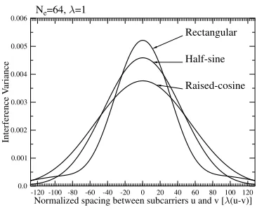
Fig. 1. Interference powerI2(k)of (9) versus the normalized spacing,λ(u−v)
between two subcarrier frequenciesfuandfvwith respect to the rectangular,
half-sine as well as raised-cosine chip waveforms.
U=8,N1=128,L1=32,K=10, =0.2,Eb/N0=15dB,L=Lp
m=1
m=3
0 30 60 90 120 150 180 210 240 Normalized spacing ( )
10-6 2 5
10-5 2 5
10-4
2 5
10-3
BER
[image:4.612.334.514.338.483.2]Raised-cosine Half-sine Rectangular
Fig. 2. BER versus the normalized subcarrier spacing,λfor the generalized MC DS-CDMA system communicating over the multipath Nakagami-mfading channel using the fading parameters ofm= 1andm= 3. The results were computed from (25) by assuming thatL=Lp, i.e. that the receiver was
capa-ble of combining all the resolvacapa-ble paths, regardless of the associated receiver complexity.
U=8,N1=128,L1=32,K=10, =0.2,Eb/N0=15dB,L=8
m=1
m=3
0 30 60 90 120 150 180 210 240 Normalized spacing ( )
10-6 2 5
10-5 2 5
10-4
2 5
10-3
BER
[image:5.612.340.517.113.258.2]Raised-cosine Half-sine Rectangular
Fig. 3. BER versus the normalized subcarrier spacing,λfor the generalized MC DS-CDMA system communicating over the multipath Nakagami-m fad-ing channel usfad-ing the fadfad-ing parameters ofm= 1andm= 3. The results were computed from (25) by assuming that the maximum multipath combining capability wasL= 8, i.e. that the receiver was capable of combining at most eight resolvable paths due to implementation complexity limitations.
the interference power at the point ofλ(u−v) = 0is more than twenty times higher, than that at the point ofλ(u−v) = 2Ne= 128. Therefore, we can infer that in a MC DS-CDMA system, the MPI and the MUI are mainly contributed by the specific subcarrier signals hav-ing overlapphav-ing main lobes.
The influence of the normalized subcarrier spacing,λ, on the aver-age BER of the generalized MC DS-CDMA system is shown in Fig.2 and Fig.3, where we assumed Nakagami fading parameters ofm= 1 and 3. In the context of Fig.2 we assumed that the receiver was capable of combining all the resolvable paths, i.e. we hadL=Lp, regardless of the implementing complexity. By contrast, we assumed that the re-ceiver was capable of combining at mostL= 8resolvable paths in Fig.3, owing to implementing receiver complexity limit. At the top of Figs.2 and 3N1andL1represent the spreading gain and the number of resolvable paths of a corresponding conventional single-carrier DS-CDMA scheme using the same total bandwidth, as the proposed MC DS-CDMA arrangement.
From the results of Fig.2 we infer that the multicarrier system us-ing both the half-sine and the raised-cosine chip waveforms achieved their lowest BER at low normalized subcarrier spacing values ofλ, while single-carrier DS-CDMA associated withλ= 0achieved the best BER performance. However, the multicarrier system using the rectangular chip waveform might not achieve its lowest BER, when the normalized spacing value is low, especially for channels having relatively high Nakagami fading parameters, since the associated BER curve has its minimum value in the range ofλ ≈ 180−210. Ac-cording to the results of Fig.3, we observe that for each of the chip waveforms considered, there exists an optimum value ofλ, which will result in the minimum average BER. The optimum value ofλwas sim-ilar for all three types of chip waveforms, which was aroundλ= 215.
Furthermore, from the results of both Figs.2 and 3 we observe that when the normalized spacing ofλassumes a sufficiently high value, the MC DS-CDMA systems using any of the three chip waveforms studied achieved a similar BER performance.
In Fig.4 the BER performance versus the fading parameter, m
recorded for the MC DS-CDMA system having the optimum
sub-U=32,N1=128,L1=32,K=10, =0.2,Eb/N0=12dB
L=5
L=10
L=Lp
0 1 2 3 4 5 6 7 8 9 10 11 12 Fading parameter, (m)
10-6
2 5
10-5 2 5
10-4 2 5
10-3 2 5
10-2
BER
[image:5.612.88.264.113.255.2]Raised-cosine Half-sine Rectangular
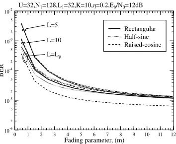
Fig. 4. BER versus the fading parameter,m, for MC DS-CDMA having the optimum normalized subcarrier spacing and using rectangular, half-sine as well as raised-cosine chip waveforms, when communicating over multipath Nakagami-mfading channels. The results were computed from (25) by as-suming that the maximum multipath combining capability wasL= 5,10or
L=Lp.
carrier spacing was evaluated, when employing rectangular, half-sine and raised-cosine chip waveforms, respectively. From the results of Fig.4 we observe that for the diversity combining capability ofL= 5
and 10, the MC DS-CDMA systems using the rectangular, half-sine or raised-cosine chip waveform achieved a similar BER performance, when communicating over channels having arbitrary Nakagami fad-ing parameters. However, if the receiver was capable of combinfad-ing an arbitrary number of resolvable paths, i.e. when we hadL=Lp, we observe that the system using the raised-cosine chip waveform outper-forms both that using the rectangular and the half-sine chip waveoutper-forms. We can also see in Fig.4 that the scheme employing the half-sine chip waveform outperforms that using the rectangular chip waveform, when the Nakagami fading factor is in the range ofm≤7. By contrast, both of them achieve a similar BER performance, when we havem >7.
REFERENCES
[1] L.-L. Yang and L. Hanzo, “Performance of generalized multicarrier DS-CDMA over Nakagami-mfading channels,”IEEE Trans. on Commun., vol. 50, pp. 956 – 966, June 2002.
[2] L.-L. Yang and L. Hanzo, “A unified approach to the analysis of multi-carrier DS-CDMA over Nakagami-mfading channels,” inProc. of IEEE GLOBECOM, (San Antonio, Texas, USA), Nov. 25-29, 2001.
[3] M.-S. A. Marvin K. Simon,Digital Communication over Fading Channels: A Unified Approach to Performance Analysis. New York: John Wiley & Sons, 2000.
[4] L. Vandendorpe, “Multitone spread spectrum multiple access communica-tions system in a multipath Rician fading channel,”IEEE Trans. on Veh. Tech., vol. 44, no. 2, pp. 327–337, 1995.
[5] E. A. Sourour and M. Nakagawa, “Performance of orthogonal multicarrier CDMA in a multipath fading channel,”IEEE Trans. on Commun., vol. 44, pp. 356–367, March 1996.
[6] M. A. Laxpati and J. W. Gluck, “Optimization of hybrid SFH/DS MFSK link in the presence of worst case multitone jamming,”IEEE Trans. on Commun., vol. 43, pp. 2118–2156, June 1995.
[7] L.-L. Yang and L. Hanzo, “OverlappingM-ary frequency shift keying SSMA systems using random signature sequences,”IEEE Trans. on Veh. Tech., vol. 48, pp. 1984–1995, November 1999.