459
©IJRASET: All Rights are Reserved
Different Effect of Sliding Mode Controller on DC-DC Boost
Converter with Output Voltage Variation Analysis
Karuna Kumari1, Dolly Murodia2
1, 2
Electrical Department, Rajasthan Institute Of Engineering And Technology
Abstract: In current days, solar, wind and PV are Maximam used for increases power as per essential and generation. The power which is received from source of energy required to be converted using AC to DC or DC to DC converters. The Boost converter is used for step up this voltage. These kind of sources are capable of being adjusted by nature, thus the problem arises to maintain constant imposible to avoid output in all conditions.The Boost converter converts the low value of input voltage into higher value of output voltage when recive the input. By using sliding mode control of the converter this problem of gaining constant output under variable conditions can be solved. To implement this technology there are many schemes with converter but the problem arises when the parameter changes capacitance and inductance as load varies. In Similar work is to resolve this kind of problem with the help of competitive analysis of Slide Mode controlled compared in terms of transient characteristics load and other parameters variations with PID controller, these controllers are evaluated and modeled by MATLAB simulations. The voltage of input source is taken as DC source at variable conditions. This modeling is done in MATLAB/Simulink software. Keywords - DC to DC boost converter, Slide Mode controller(SMC), Proportional- Integral- Derivative(PID) controller.
I. INTRODUCTION
DC-DC switch mode converters electronics circuit which is used to convert a voltage from higher to lower level. They much more used in some electronic device like DC drive system, Smart grids, and distributed power supply system. In current days, DC-DC power converters are used in generation of energy with help of solar and wind system. The power which is composed from these sources is converted with help of AC-DC and DC-DC converters but the which is gained form these are flexible in nature. So, for continues production and get complete output voltage many controlled converts are used. DC-DC switching type converters are commonly used and one of the best power electronics circuits which convert unregulated electrical voltage from one level to regulated desired another level electrical voltage by switching technique and eliminated unfiltered output issue can be solved through SMC. There are many option to contrivance this with converted, but the difficult arise when in the form of capacitance installation and the load varies. The converts benefits in electricity system is regulate the parameters giving difference in maintenance & load the essential creation voltage to control the output voltage of converter we can use to control semi control device at duty cycle. The idea of work by controlling method to control the duty cycle according to changes the several parameters of structure by using SMC.A different method has been ready to control the duty cycle on converter and to increase system effectiveness for all parameter. In this paper, It’s shows performance of slide mode controller DC-DC buck convertor compared with PID controller in basis of load and different parameter variation. These kind of controller are evaluate by MATLAB simulation and modeled also.
A. Boost Converter
A Boost converter is like a power converter which can convert small value of input voltage to higher of output voltage. It’s like switching mode power supply containing minimum of 2 semiconductor switch(Diode, Transistor ) and minimum one energy part.
Fig.1. Schematic diagram of boost converter
A configuration of boost converter has controller power transistor a inductor (L), Switch (S), Diode (D) Capacitor (C) and a Load (R). Assume that the converter is operating in continuous condition mode Fig.2. when switch is on input voltage (Vi) across inductor (L),
460
©IJRASET: All Rights are Reserved
= … (1)
LOAD L + + -+ + VC C M1 G Vi - - -IL ID IC Vo D
Fig.2 Circuit diagram of Boost Convert
When the one state end the increases current during time is
…. (2)
So, Diode D is duty cycle, It’s shows how much of the duration of which the switch is turned on. So D range from 0 to 1. And when switch is off the load has inductor current across it shown in fig 2. Considering Zero voltage drop D maintains capacitor great for it’s voltage to remain constant.
.... (3)
So, In switch off period the inductor current varied,
…. (4)
The inductor current should be same from starting and ending of commutation cycle. So, when change the current is zero:
…. (5)
Substituting and from (2) and (4) in (5). This can be written as:
… (6)
It shows the relation between output voltage and duty cycle. So, it’s clear shows that for control the output voltage through duty cycle , where D is changed from 0 to 1.
II. CONTROLLERDESIGNMETHODOLOGY
The main aim of control in DC-DC boost control the output (V0) t of DC voltage at given reference value (Vref). Main concept in
this process is to control he accepted out in the existence of the input voltage derivations and load disturbance. The conventional
controller sliding mode control is proposed to regulate the output voltage V0 of the converter.
A. Proportional-Integral-Derivative Controller
1) In industry area’s for controlling he system commonly used PID controller. It is feedback control loop mechanism. PID
controller is a perfect error among a measured and wanted variable set point as shown in fig 3. PID controller control 3 different parameters Integral, Proportional and derived values is control the response the error of current the integral bound response created on the sum of latest error and control the response to the derived rate which the error is varying.
Proportional
Pout=kp*e(t)
Derivative
D out=K d*de/dt
Integeral
Iout=ki*∫e(t)dt
∑ Process
∑ Error Val ue
+
+ + +
-Con trol Sign al
Feedback Val ue
461
©IJRASET: All Rights are Reserved
B. Sliding Mode Controller (SMC)
The sliding mode voltage controller is helpful because of it’s high performance in easy implementation. The concept of sliding mode controller includes designing a slide surface within the state space and a control low. Which should direct the system trajectory into slide surface. A pre define surface is sliding surface in the state space region.
To design a slide mode controller (SMC) converter assume that output voltage is a control variable and a state variable of full order slide mode controller which controlled can be expressed by variables X.
…. (7)
Where X1, X2, X3 are voltage error, rate of change of voltage error, and the integral of voltage error. is voltage reference
is sensed output voltage, is gain/proportion of sensed output voltage and MOSFET M1 is control switch. In this system, a normal sliding mode control rule that use the control or switching function can be written as,
… (8)
Where,
S is the instantaneous state variable trajectory. It can be represent as,
…. (9)
The a1, a2,a3 are control parameter known as sliding coefficients. For the SMVC boost converter , The deviations are as illustrated.
Equating gives the equivalent control function.
…. (10)
is continuous are 0 < . Since , this also implies.
Equivalent control function is mapped into the duty radio control:
Where, , given the relationships for ramp and the control signal .
Where, is
…. (11)
Calculation of control signal (11) can be done using modest summing gain and utilities. The parameters of circuit can be
normally calculated by known values , are poper selections of a1, a2, a3.
III.SIMULATIONANDRESULTANALYSIS
This is explain design and modeling of DC/DC boost converter with controller. The model is based on mathematical calculation and modifications and design is represent MATLAB/Simulink . This kind of work shows control and working of DC/DC boost
converter with PID controller and sliding mode controller (SMC). The factors fixed on different condition, the proposed system is given the output of all the different condition.
462
[image:4.612.117.543.82.259.2]©IJRASET: All Rights are Reserved
Fig. 5 Simulink Diagram for Boost Converter with SM controller at 200V to 400 V
IV.DESIREDOUTPUTVOLTAGEVARIATIONANALYSIS
[image:4.612.79.535.298.456.2]Fig.6 Input Voltage from Boost converter
[image:4.612.85.527.504.682.2]This diagram represent the input waveform in Boost Converter for voltage with help of PID and SMC. So, when the operation mode for 200V to 350V and 400V conversions. It can be observed from waveform when input voltage in 200V.
Fig.7 Input Current from Boost converter using PID controller.
463
©IJRASET: All Rights are Reserved
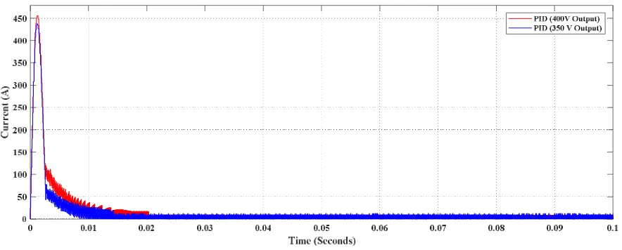
Fig.9 Output Current from Boost converter Using PID controller.
Fig.9 Represent the output waveform in boost converter for current using PID controller when the mode of operating is 200V to 350V and 400V conversions. It can be observed from waveform when output current is 1.464A for 350V and 1.67A for 400V.
Fig.10 Output Voltage from Boost converter Using PID controller.
Fig.10 Represent the output waveform in Boost Converter for voltage using PID controller. When the mode of operating is 200V to 350V and 400V Conversion. It can be observed from waveform that the desired output can be obtained easily by varying in reference voltage of PID controller.
464
[image:6.612.81.530.85.257.2]©IJRASET: All Rights are Reserved
[image:6.612.87.531.316.476.2]Fig.11 Output Current from Boost converter Using SM controller.
Fig .11 Represent the output waveform in Boost Converter for current using SMC controller. When the mode of operating is 200V to 350V and 400V conversion. It can be observed from waveform when ouput current is 1.458A for 350V and 1.666A for 400V.
Fig.12 Output Voltage from Boost converter Using SM controller.
Fig.12 Represent the output waveform in Boost Converter for voltage using SMC when the mode of operating is 200V to 350V and 400V.
Compare between output responses of SM Controller PID controller by varying reference voltages.
Table I
Controller Desired
Output Voltage
Output Voltage Output Current Settling
Time
Slide Mode Controller 350 350 V 1.456 A 2.018 milliseconds
400 399.9 V 1.666 A 3.460 milliseconds
PID Controller 350 351.3 V 1.464 A 9.224 milliseconds
400 400.9 V 1.670 A 12.508 milliseconds
465
©IJRASET: All Rights are Reserved
V. SUMMARY
In this topic of the represents the simulation analysis using data analysis and output waveform of model using boost converter implementing slide mode controller and PID controller. So, the conclusion of this chapter concise that SM controller is best suitable to obtain the different values the PID controller and also it’s possible to obtain a desired output by changing control parameter further, the transient setting time around 3.5 ms , and it is also independent of magnitude and direction of step load change and the operating input voltage. It shows the strength of SMC in terms of robustness in dynamic behaviour at different operating condition.
VI.CONCLUSION
This research shows that the analysis between two controller one is PID (Proportional Integral Derivative) and other one is SMC (Sliding Mode Controller). The designed controller are feeding resistive load analysis the result is different condition at integrated converter and controllers attained zero steady state error. The work is carried out by two different condition, first is when the operating mode is for 200V to 400V and the second one is operating at 350V to 400V. A system is designed in MATLAB and calculate the increase time, setting time, overshoot from the graphical response of voltage. Which is achieved from MATLAB. The maximum comparative simulation output waveform between two controller. Which shows that the system works more effective at higher voltage rating and decrease the output current. As compare to the result of PID and sliding mode controller (SMC) in the case of stability slide mode controller in the case of stability slide mode controller is more perfect and time is less then PID. The data analysis shows in table all specific results with sliding mode controller compare to PID controller.
REFERENCES
[1] Asma, Z. Abdelaziz and Z. Nadia, "Dual loop control of DC-DC boost converter based cascade sliding mode control," 2017 International Conference on Green Energy Conversion Systems (GECS), Hammamet, 2017, pp. 1-6.
[2] S. Ahmadzadeh, G. Arab Markadeh and F. Blaabjerg, "Voltage regulation of the Y-source boost DC–DC converter considering effects of leakage inductances based on cascaded sliding-mode control," in IET Power Electronics, vol. 10, no. 11, pp. 1333-1343, 9 9 2017.
[3] İ. Yazici and E. K. Yaylaci, "Fast and robust voltage control of DC–DC boost converter by using fast terminal sliding mode controller," in IET Power Electronics, vol. 9, no. 1, pp. 120-125, 1 20 2016.
[4] S. Barhoumi, A. Sahbani and K. Ben Saad, "Sliding Mode Control for a Boost converter with Constant Power Load," 2016 4th International Conference on Control Engineering & Information Technology (CEIT), Hammamet, 2016, pp. 1-5.
[5] Xuemei Zheng, He Li, Rui Song and Y. Feng, "Full-order terminal sliding mode control for boost converter," 2016 IEEE 8th International Power Electronics and Motion Control Conference (IPEMC-ECCE Asia), Hefei, 2016, pp. 2172-2176.
[6] Yanmin Wang, Yuqing Cao, Tienan Liu, Hongwei Xia and Bao Ding, "Terminal sliding mode control of boost converter using an energy storage function model," IECON 2016 - 42nd Annual Conference of the IEEE Industrial Electronics Society, Florence, 2016, pp. 354-358.
[7] Souvik Dasa,Mohd Salim Qureshib, Pankaj Swarnkarc, “Design of integral sliding mode control for DC-DC converters,” in 7th International Conference of Materials Processing and Characterization 5 (2018) 4290–4298.
[8] Humam Al-Baidhani and Marian K. Kazimierczuk, “PWM-Based Proportional-Integral Sliding-Mode Current Control of DC-DC Boost Converter,” IEEE Trans. Power Electron.2018.