Research Paper
Nu mer ica l St udi es of Pie zoe lect ric Co mpo sit es Usi ng N URB S f or
Geometry and Field Functions
A V SINGH*and V RAJ
Mechanical and Materials Engineering, Western University, London,Ontario, Canada, N6A 5B9
(Received on 20 May 2016; Accepted on 28 May 2016)
This paper deals with the response studies of piezoelectric sandwich composites by the energy method. The equation of motion is deduced from the principles of minimum potential energy. To do this displacement and electrical fields are required as a priori. Hence, the above said field functions are described by Non-Uniform Rational B-Splines (NURBS) in two and three dimensional domains and applied against static and free vibration analyses of thin and very thick sandwich plates and piezoelectric prismatic bar. Nonlinear variation of the electric potential is considered through the thickness and modelled by a discrete layer-wise linear scheme. The present formulation is successfully validated against a finite element code.
Keywords: Energy Method; Piezoelectric Composites; Sandwich Plates and Beams; Electro-Elastic Composites; NURBS
*Author for Correspondence: E-mail: [email protected]
Proc Indian Natn Sci Acad 82 No. 2 June Spl Issue 2016 pp. 361-367
Printed in India. DOI: 10.16943/ptinsa/2016/48427
Introduction
Piezoelectric materials receives attention due to their potential use as sensors and actuators in vibration control systems. Constitutive equations for piezoelectric devices have been developed and reviewed in the literature by many (EerNisse, 1967; Bleustein and Tiersten, 1968; Tiersten, 1969). The coupled electro mechanical equations are understandably too complex to obtain closed form solution in most cases. Nevertheless researchers have been able to model this effect by analytical techniques for certain boundary and loading conditions. Various theories based on beam, plate, shell and solid models were developed by some researchers (Crawly and de Luis, 1987; Im and Atluri, 1989; Jiang et al., 1991; Wiciak, 2012). Such analytic models were used for piezoelectric actuators and sensors. On the other hand, many resorted to the finite element method as a viable modelling technique. Allik and Hughes (1970) implemented a finite element formulation for electro-elasticity and developed tetrahedral element for the vibration analysis. Hwang and Park (1993) analyzed vibration control of laminated plates with integrated
piezoelectric sensors using a quadrilateral plate element with 12 degrees of freedom. Tzou and Garde (1989) analyzed electro-elastic Kirchhoff-Love plates. Their results were acceptable for thin sandwich plates, but diverged for moderately thick ones. Two-dimensional theories for plates and shells involving layer-wise approximation of the electric potential through the thickness produced a viable modelling technique for moderately thick piezoelectric laminates. Saravanos (1997) developed the mechanics of mixed laminate theory for composite shell structures, in which a layer-wise distribution of electric potential was considered. He reported numerical results for cylindrical laminated piezoelectric panels. Heyliger et
al. (1996) used finite element method to develop a
Accordingly, researchers used a two-dimensional plate or shell model with layer-wise mechanics and higher order polynomial approximation for electric potential in the thickness direction (Detwiler et al., 1995; Heylinger et al., 1996; Fernandes and Pouget, 2001). These models are quite adequate and served the purpose they were for. When the plate gets thicker, the two dimensional models are not quite as efficient. Also in all of the above models the electric potential variation is subjected to some degree of approximation. Such severe limitations in two dimensional modelling warranted development of three dimensional modelling techniques. Ghandi and Hagood, (1996) developed an eight node element, each having three mechanical and one electrical degree of freedom, to model phase transition of electro-mechanical materials. Koko et al. (1997) used a 20 node thermo-piezoelectric element for modelling smart composite structures. They reported a comprehensive analysis on controlling the vibrations of a composite piezoelectric structures. Lim et al. (1997) performed transient response analysis on MEMS scale piezoelectric sensors. For it, they used a combination of 20 node solid element, 13 node transition element and 9 node shell element to model a cantilever plate with embedded piezoelectric sensor. Although, three dimensional modelling of piezoelectric materials proves to be an efficient method, it also has some limitations. The associated difficulties include locking effects and increase in degrees of freedom. The shear locking effect is encountered while modelling relatively thin plates with solid elements. To alleviate the locking problem, selective integration technique in the thickness direction was used by Braess and Kaltenbacher (2008) while using a three dimensional solid element. It is evident from the above brief literature survey that a much needed attention has to be paid towards modelling piezoelectric crystals and thick laminated plates and shells.
The present study aims to propose an efficient and reliable numerical technique that makes use of the Non-Uniform Rational B-splines (NURBS) to represent geometry and displacement fields (Piegl and Tiller, 1997). These splines are quite capable of modelling complex geometrical shapes using only a few control points and have higher order continuity compared to the traditional finite elements. A quadrilateral domain with curved edges is considered for the first order shear deformable plate problems.
Similarly, a hexahedral solid, enclosed by six curved surfaces, is taken as the basic three dimensional geometry. Also, the splines with different degrees and numbers of control points can be used to define the mechanical and electrical field-functions pertaining to displacement and electric charge. This translates into fewer number of degrees of freedom while pursuing formulation of a full three dimensional solid patch. Another advantage of using a three dimensional model is its inherent ability to incorporate the electromechanical coupling effectively. This flexibility in curve generation is exploited further to define the geometry as well as displacement fields in the variational method for three dimensional electro-elastic problems. The present method is successfully tested against well-established finite element code ANSYS. Static and free vibration analyses performed on cantilever sandwich piezoelectric plates reveal discrepancies in the values of deflection and natural frequencies, if first order shear deformable and three dimensional theories are used for considerably thick plates. Difference in the value of natural frequencies also increases with mode number. Results on the vibration of a prismatic bar are also computed and compared favorably with those from ANSYS.
NURBS Curves
A NURBS curve C() can be described in the parametric space– 1<< + 1 as follows.
( ) k i( ) i
C R p (1)
where kRi( ) = kNi( ) wi/ k ( )
j j
N w and the
summation is performed over i = 0 to n. Also,kNi( ) = theB-spline basis functions of degree k (or order
k+1), pi = control point vector and wi = weight vector. Knot vector i is a set of non-decreasing parametric coordinates and constructed for an open curve through the following equation.
0 0 1
1 1 1
2 1 1
i
i k
i k k i n
n k n i n k
(2)
1
0...0, ,...., 1...1
i k n
(3)
Such parametric curve can be continuously differentiated k – 1 times provided that the knot vector
is without multiplicity. Once the unidirectional curves are defined separately in x, y, z directions, a NURBS solid can be created by the tensor product of the three parametric curves.
, , , ,
( , , ) q r ( , , ) q r
C R p (4)
The triple summations are performed on the number of control points in each direction. The order and number of control points can be the same in all directions or different for each direction. Additionally, knot insertion and removal techniques can be used to change the number of the control points.
Formulation
A general description of the formulation for a sandwich structure with piezoelectric face sheets and elastic core ispresented in this section. There are two models that are considered in this study. In the extremely simplified model one, the sandwich structure is assumed as a singlefirst order shear deformable plate. Accordingly, the in-plane displacement varies linearly over the entire thickness of the composite plate, while the transverse displacement remains the same for all layers. Displacement at an arbitrary point in the plate under this assumption can be described by the displacement and rotation components at the middle plane of the plate, which is also known as the reference plane. It is considered to have four curved boundaries. NURBS curves are used to define the four curved boundaries taking benefits from the natural coordinates
–1< (,) < 1. Three translational components and two rotational components of thenormal to the plate at the reference plane are denoted by u1, u2, u3, 1 and 2 respectively. The electrical charge that develops in the piezoelectric layer during bending, is known to vary nonlinearly in the thickness direction. In order to incorporate this nonlinear distribution of along the thickness, a layer is divided into a number of sublayers and linear distribution is taken in each sublayer. Both, the displacement and rotational components are expressed by NURBS surfaces and their control points are the degrees of freedom.
For the second model, each layer is taken as a
hexahedron formed by six curved NURBS surfaces
defined innatural coordinate system –1 <,,< 1. Displacement and potential are expressed in a similar manner as the triple summation in Eq. (4). Controls points for the four (three displacements u1, u2, u3 and one potentialfields constitute the degrees of freedom at a point in the continuum.
The material equations relating stress {}, electric flux density {D}, mechanical strainan {} delectric field {E} are:
{} = [C]{} – [e]T{E} (5)
{D} = [e]{} + []{E} (6)
Where [C] = elastic stiffness matrix, [e] = piezoelectric coupling matrix, and [] = dielectric matrix (Allik and Huges, 1970). Mechanical strains can be expressed in terms of u1, u2, u3, etc. In addition,
Maxwell’s equation [E] = –{} is used to express the electric field {E} in terms of the electric potential
. These are then substituted in the energy functional = T –U –W, in which U = the strain energy, T =
the kinetic energy and W = the work done by externally applied electrical and/or mechanical loads. After applying the stationary condition on the energy functional, two coupled equations can be obtained. By eliminating the electric potential, the two are merged into one equation of motion for the forced vibration analysis of a piezoelectric structure.
[M]{ } [ ]{ }C [ ]{ }K { ( )}F t (7)
Here, vector of control points associated with mechanical displacement = {}. Others are:over-dot = time derivative, [M] = mass matrix, and [C] = damping matrix. Also, the stiffness matrix and the force vector are
1
[ ]K [Km] [ Kme] [Ke] [ Kem]
and 1
{ ( )}F t {F tm( )} [ Kme][Ke] { Q ( )}t (8)
Numerical Examples
In this section, results are presented and discussed first for the static bending and free vibration of cantilevered sandwich plates of thickness h. Fig. 1 shows geometry of the reference plane of the plate considered for the static bending. The plate tapers in width from b = 100 to c = 50 over a length of a = 150, all in millimeters. The stacking layout is ZnO+/Si/
ZnO–. The three layers are of equal thicknessesand
a uniformly distributed load of one kPa is applied on the top surface. Displacement and rotation are set to zero at the left vertical edge for the plate, i.e., u = v =
w =1= 2 = 0 for the first order plate problem. Only the conditions: u = v = w = 0 at the fixed edge are applied in the case of the three dimensional model. The top and bottom interfaces of piezoelectric layers are grounded by making = 0.
Numerical simulations are performed using both two and three dimensional NURBS models. Patches and blocks for various aspect ratios and mesh configurations are considered keeping order of the NURBS functions at four. Control knots on the boundaries are generated according to the shape of the plate. The inside control points are linearly interpolated. A basic plate patch has control points for the middle plane, whereas a mesh of 5 x 5 x 5 control points per module is considered in hexahedral continua. Anine patch 3 x 3 plate model with six piezoelectric sub layers has 1280 mechanical and 1792 electrical degrees of freedom. The same in one solid module, for example, amounts to 375 corresponding to (u1, u2, u3) and 125 to. Hence, ina 3×3×3 solid model there are 125 control points/module, 6591
mechanical and 2197 electrical to a total of 8788 degrees of freedom.
Values of the maximum free edgetransverse displacements are presented in Table 1 for six a/h ratios covering thin to very thick plates. Displacements found from the solid formulation are higher than those from the plate theory for the thick plates. Both plate and full three dimensional modelsyieldclose results with a difference of 0.21 percent for large a/h = 100. However, the difference 4.41 percent in the case with
a/h = 10 grows to 8.08 percent with a/h = 5.
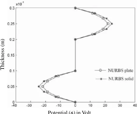
Distributions of the electric potential calculated along the thickness from 2 and 3 dimensional cases are plotted in Fig. 2 for the case with a/h = 5. It is inferred that the solid model estimates higher electric potential across the thickness up to a maximum of 10.3 percent. There is no approximation involved in electrical potential variation along the thickness in the solid model. The electromechanical coupling is seen to be effectively sustained.
[image:4.612.73.295.83.234.2]Fig. 1: Reference plane for the plate
Table 1: Displacement in (m)
a/h Plate model Solid model Difference (%)
100 1135.0 1132.6 0.21
75 472.5 475.3 0.60
50 144.3 146.0 1.19
25 17.8 18.4 2.81
10 1.16 1.21 4.41
5 0.15 0.16 8.08
Fig. 2: Distribution of the electric potential across the th i c kne ss
Potential ( ) in Volt
T
h
ic
k
n
es
s
(m
[image:4.612.318.546.100.211.2] [image:4.612.318.543.525.713.2]Free vibration analysis is performed on a rectangular sandwich plate with a = 150, b = c = 100 in millimetres and the stacking layout of ZnO+/Si/
ZnO–. Direct iteration method is used in the
homogeneous equation of motion to obtain the first five natural frequencies in radian per second for a/h = 100, 50 and 5 as shown in Table 2. Columns three and four contain results from the plate and solid NURBS models respectively. Fundamental frequencies for the three a/h ratios for these cases are found in extremely good agreement. It is not so for higher modes of vibration. Difference in the fundamental frequencies seems to be increasing with the thickness. This can be due to over simplified assumption made in the plate model. Still results from the plate theory is significant in the sense that the participation rate of the fundamental mode in transient response conditions is generally very high. The present study shows that the simple first order shear deformable plate model can yield reasonably reliable results in transient response analyses. Finite element analysis in ANSYS is also performed and the results are presented in the fifth column in Table 2. The model is created with solid 226 coupled field elements for the piezoelectric layer and solid 185 for theSi core. The assembled model has 129546 degrees of freedom, which is approximately fifteen times the NURBS based solid model. This clearly demonstrates a huge advantage of the present method over the conventional finite element method. Results from NURBS and ANSYS models show resounding agreement. The
mode shapes, which are not included in this paper because of the space limitation, are also seen to match mode-by-mode.
A cantilevered homogeneous prismatic PZT4 piezoelectric bar is studied next as a benchmark problem. The material properties for PZT4 are also presented in the appendix. The bar is 15 cm long and 5 x 5 cm2 in cross section. The clamped end conditions, u = v = w = 0, are enforced and the top and bottom
surfaces are grounded by making electrical potential
= 0. The bar modelis created with a grid of 5 x 5 x 5 solid modules, each having 125 control points. The model consists of 6591 mechanical degrees of freedom pertaining to (u, v, w) and 2197 electrical degrees of freedom to a sum of 8788. The same bar is modelled in ANSYS environment using solid 226 coupled field elements with a total of 65066 degrees of freedom. Values of the first eight natural frequencies in Hz, calculated by the present solid model and the ANSYS, are presented in Table 3. The results show extremely close agreement. The mode shapes, though not included in this paper, were also examined and found consistent in both analyses.
Closing Remarks
[image:5.612.317.546.101.253.2]Efficient computational methods in two and three dimensions are developed for piezoelectric laminates with full electro-mechanical coupling. NURBS are used in representing the geometric coordinates, mechanical displacement components and electric charge field. Static analysis is performed ona cantilevered trapezoidal piezoelectric sandwich plate using both: two dimensional first order shear deformable plate andthree dimensional continuum Table 2: Natural frequencies of rectangular sandwich
platein (rad/sec)
a/h Mode number Plate model Solid model ANSYS
100 1 389 385 385
2 1432 1222 1221
3 2371 2445 2443
4 4746 4214 4215
5 5999 5979 5977
50 1 803 798 799
2 2846 2433 2431
3 4730 4874 4874
4 8419 8377 8375
5 11935 11905 11913
5 1 7651 7558 7559
2 19921 19520 95321
3 23101 19905 19925
4 39533 40083 40104
[image:5.612.64.294.543.739.2]5 59513 57559 57570
Table 3: Natural frequencies for PZT4 bar in (rad/sec)
Mode 3D solid 3D ANSYS Difference
number (%)
1 1125.6 1121.8 0.34
2 1141.5 1151.4 0.87
3 2980.1 2981.7 0.06
4 4947.5 4939.7 0.16
5 5124.1 5134.9 0.21
6 5684.2 5554.9 2.33
7 8936.1 8910.2 0.29
theories. Studiesreveal discrepancies in results, when the plate theory is used for considerably thick sandwich composites. Free vibration analysis is performed on a rectangular sandwich plate to validate the efficiency of the present NURBS based methods. The fundamental frequencies of the piezoelectric sandwich platesfrom the plate and solid models are close. Hence, the use of the present platemodel should be adequate in sensing, actuating and power harvesting applications. In such cases, generally the fundamental mode of vibration is triggered to a significant extent. The present three dimensional NURBS based and finite element methods yield very close results as well. However, there is a huge difference in the numbers of the degrees of freedom in the two models. This can be quite significant particularly in transient response analyses.
Appendix: Material Properties
C1! Si ZnO PZT4 Unit
C12 166.0 209.700 139.00
C33 63.9 121.100 77.80 (Gpa)
C13 166.0 210.900 115.00
C44 63.9 105.100 74.30
e31 79.6 42.500 25.60
e33 0.0 –0.610 –5.20 (C/m2)
e15 0.0 1.140 15.10
C12 0.0 –0.590 12.70
11 0.1045 0.074 13.06 (nF/m)
33 0.1045 0.074 11.51
2329.0 5606.000 7500.00 (kg/m3)
References
Allik H and Hughes T J R (1970) Finite element method for piezoelectric vibration International Journal for Numerical
Methods in Engineering 2 151-157
Bleustein J L and Tiersten H F (1968) Forced Thickness-Shear Vibrations of Discontinuously Plated Piezoelectric Plates
Journal of the Acoustical Society of America 43 1311-1318
Braess D and Kaltenbacher M (2008) Efficient 3D – finite element formulation for thin mechanical and piezoelectric structures
International Journal for Numerical Methods in Engineering 73 147-161
Crawley E F and de Luis J (1987) Use of piezoelectric actuators as elements of intelligent structures AIAA journal 25 1373-1385
Detwiler D Shen M-H and Venkayya V (1995) Finite element analysis of laminated composite structures containing distributed piezoelectric actuators and sensors Finite
Elements in Analysis and Design 20 87-100
EerNisse E P (1967) Resonances of One-Dimensional Composite Piezoelectric and Elastic Structures Sonics and Ultrasonics,
IEEE Transactions on 14 59-66 H
Fernandes A and Pouget J (2001) Two-dimensional modelling of laminated piezoelectric composites: analysis and numerical results Thin-Walled Structures 39 3-22
Ghandi K and Hagood N W (1996) Nonlinear finite element
modeling of phase transitions in electromechanically coupled material, Symposium on Smart Structures and
Materials, International Society for Optics and Photonics,
121-140
Heyliger P Pei KC and Saravanos D (1996) Layerwise mechanics and finite element model for laminated piezoelectric shells
AIAA Journal 34 2353-2360
Hwang W S and Park H C (1993) Finite element modeling of piezoelectric sensors and actuators AIAA Journal 31 930-937
Im S and Atluri S N (1989) Effects of a piezo-actuator on a finitely deformed beam subjected to general loading AIAA
Journal 27 1801-1807
Jiang C S Abe Z W and Tani H (1991) Position control of a flexible arm using piezoelectric bimorph cells Journal of
Dynamic Systems, Measurement, and Control 113
327-329
Koko T S Orisamolu I R Smith M J and Akpan U O (1997) Finite-element-based design tool for smart composite structures Smart Structures and Materials’ 97,
International Society for Optics and Photonics 125-134
Lim Y-H, Varadan V V and Varadan V K (1997) Finite-element modeling of the transient response of MEMS sensors Smart
materials and structures 6 53
Piegl L A and Tiller W (1997) The NURBS book Springer, Berlin
Rogers D F (2001) An introduction to NURBS with historical perspective Morgan Kaufmann Publishers
Saravanos D A (1997) Mixed laminate theory and finite element for smart piezoelectric composite shell structures AIAA
Journal 35 1327-1333
Press, New York
Tzou H S and Gadre M (1989) Theoretical analysis of a multi-layered thin shell coupled with piezoelectric shell actuators for distributed vibration controls Journal of Sound and
Vibration 132 433-450