4086
©IJRASET: All Rights are Reserved
Design and Implementation of PCB Prototyping
using CNC Machine
Pratik Raut
1, Himanshu Nanotkar
3, Pooja Bante
4, Priya Bareha
5, Rahul Nikhare
6, Prof. Sangeeta Palekar
71, 2, 3, 4, 5, 6Student, 7Professor, Dept. Of E.T.C Engineering, JDCOEM, Kalmeshwar/Nagpur, Maharashtra, India
Abstract: The research is focusing on design and implementation of PCB using CNC machine. Sometimes, designing a PCB, we required path image which is to be designed using some software on PC and drilling process which is a part of time delay. Therefore, to reduce the human effort and reduce the time we are changing the process of PCB designing by means of simply using CNC machine. Due to the rapid growth in the technologies and usage, the utility of CNC machine has been increased in Industries. Using CNC machine technology, one can avoid most of the procedures related to previously known technology and can also better the product quality. This paper basically focuses on the designing and implementation of automatic PCB designing using CNC machine. For programming and for 2-axis movement of CNC machine, we are using the ARDUINO board.
Keywords : CNC machine, PCB, Arduino board, Stepper Motor with Gear System, Servo Motor, L293d Motor Driver IC.
I. INTRODUCTION
There are several ways by which we can make PCB designing at high precision level with negligible errors. The idea of designing low cost PCB which involves CNC mechanism, is to full fill the low time consumption with optimized low cost. CNC mechanism allows us to avoid all the procedures, related to previously followed technologies such as, for example, the photo-chemical processes, drawing paths of PCB on computer, etc. Therefore working with automatic mechanical equipment demands precision, accuracy, speed.
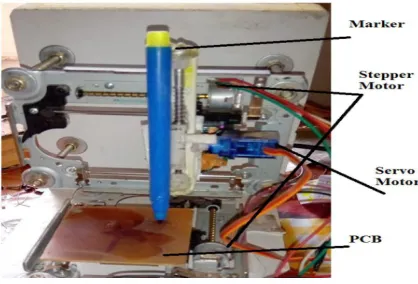
The idea behind this project is to make a small CNC machine which can draw images or pictures on surface of PCB. It uses two Stepper motors and a Servo motor as linear actuators on axis X, Y & Z respectively. At the time of printing/drawing, the proper synchronous between all three motors is really tough task. The motors are attached with the machine through proper gear assembly which provide the CNC machine 3-axis motion. We are using a marker to mark the paths on PCB. The motors are controlled with the help of Arduino UNO (atmega328) and L293d motor driver IC. In fig below a), the X,Y and Z shows the movement in that specified direction.
Fig. a) Structural representation
A. Design Idea
[image:1.595.208.417.491.633.2]4087
©IJRASET: All Rights are Reserved
machine is _x_ mm having a frame size of _x_ mm. Bipolar step working is done by stepper motor between 3-6V DC and up to 500mA. Here, 2 stepper motors are connected for controlling X and Z directions and for controlling Y direction, Servo motor of 4.8
6.5 V and 100mA which can lift up to 2.5kg/cm. Also the 555 IC (Timer IC) is used to give PWM (Pulse Width Modulation) on Orange wire of Servo motor. The PWM signal controls this motor.
II. LITERATURE REVIEW
Prabhanjay Gadhe, Vikas Jangir , Mayur Yede & Wasim-Ul-Haq used CNC machine with Arduino UNO for drilling, designing paths on PCB, drawing or designing images on paper or anything. They used G-code for programming Atmega328. Even, they used three stepper motor and a linear actuator on each axis X,Y and Z with path planning mechanism. But controlling 3 stepper motors and one AC motor to control drill, the system become more complicated and unstable.
M.R. NOWAK, A.J. ANTONCZAK, P.E. KOZEOŁ and K.M. ABRAMASKI worked on LASER prototyping of PCB.
Using LASER method for PCB designing, one can able to create double sided printing of PCB. Even, the path designing on PCB become faster. But using LASER, they made their circuit ( structure ) complex and cost inefficient.
ASHWINI GAVADE and SAYALI BIDAWAYI worked on Interfacing Stepper Motor with Arduino. Using stepper motor and servo motor, they controlled motion and drill at exact coordinates on PCB. They made their structure bulky as they used drilling machine. From all this analysis, we implement this project which can be used at small industries, school/colleges, etc because of it’s low cost and easy operated system. It gives more accuracy and increases productivity. Also it reduces manual errors by increasing comparability.
III.PROPOSED WORK
In this paper, ARDUINO UNO board uses ATMEGA 328Pmicro-controller. It can be easily interfaced with PC and also it can be easily interfaced with stepper motors and servo motor using L293d motor driving IC. The basic block diagram is as shown in Fig.1 below which consist of several different blocks. The explanation of all parameters are given below:
4088
©IJRASET: All Rights are Reserved
[image:3.595.217.383.136.246.2]A. Arduino
Fig. Arduino Board Kit.
There are many types of Arduino board like UNO, MEGA, NANO, etc. For this project, the Arduino Uno is used to control the stepper motor and servo motor. Arduino Uno is a micro-controller board based on Atmega328P. The Arduino Uno was chooses rather than other Arduino such as Arduino Lilypador Leonard because it use Atmega328 which is suitable to control stepper motor and servo motor. It has 6 analog inputs and 14 digital input/output pins (of which 6 can be used as PWM outputs), a 16 MHz crystal oscillator, a USB type-B connection, a power jack, an ICSP (In-Circuit Serial Program ) header, and a reset button. It contains everything needed to support the micro-controller simply connect it to a computer with a USB type-A to type-B cable or power it with a AC-to-DC adapter or battery ( between 7-12 volt) to get started.
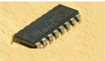
[image:3.595.215.386.409.508.2]B. Motor Driver
Fig: Schematic structure of L293d IC
[image:3.595.98.459.583.746.2]Motor Driver IC L293d is used to drive stepper motor and servo motor. Motor Driver IC is used to prevent the excess current and it meets the following specifications:-Low cost, Small size&Bipolar,4 lead wire,1.8 deg/stepTorque-2.8kg.cm,Size-33mm , Applied Voltage - 6v to 12v. Motor: There are two types of motor used: 1) Stepper Motor & 2) Servo Motor
4089
©IJRASET: All Rights are Reserved .
Fig. 1 above shows the schematic structure of TowerPro SG90 Servo Motor. The Servo Motor SG90 is used as it is small in size, having good torque of 1.8kgf.cm, having less weight of 9 gm and operating voltage of 4.8V. It’s operating speed is of 0.1 sec/ 60°. Even the operating temperature is moderate as compare to other motors of same size I.e 0° - 55°.
The above Fig. 2 shows the Stepper Motor. The Stepper Motor used in CD ROM is used here as it provide gear system for motion for printing on PCB. It having the motor body size of 15x12 mm with screw length of 58 mm. It consist of screw rod which acts as
gear which having of diameter 3 mm. The drive voltage is of 3 - 6V and it provide the coil resistance of 10Ω.
IV. WORKING
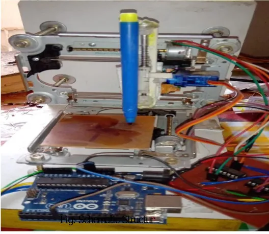
[image:4.595.191.455.314.543.2]CNC Machines which is used to draw anything or design any mechanical part according to the designed program fed into their controller unit. Controller unit can be either computer or micro-controller (depending upon the application). CNC machines have stepper and servo motors to move in the X,Y & Z coordination to draw the design as per the fed program. For a CNC plotting machine to operate, 3 axes are required I.e x-axis, y-axis and z-axis. The x-axis and y-axis work in unison (simultaneous) to create a 2D image on a plain paper. These x and y axis are placed 90 degrees to each other such that any point on the plain surface is being defined by a given value of x and y axis. The z-axis is used to lift up and down the pen onto the plain paper.
Fig: Schematic Structur
Depending on the image to bedrawn, the computer will generate the appropriate coordinates and send them to the atmega328 (which is used as a micro-controller) through the USB port. The atmega328 interprets these coordinates and then controls the positions of the motors to create the image.
We have used Arduino UNOand motor driver IC’s to build this CNC Machine. To make x and y axis, two DVD mechanism (used to move Lens in DVD player) are used. Each of these parts contains a stepper motor and a belt drive mechanism
usually used to move the cartridge to and fro. For the z-axis, a mini servo motor (SG90) is attached on the y-axis using
adhesive. This servo motor is used to move the marker up and down.The Stepper Motors used are bipolar. The wiring of these stepper motors are connected to the output pins of L293d motor driver IC which is of 16 pin. The input pins of the motor driver IC are connected to the pins of Arduino board.
For the efficient operation of this machine, the following software’s are used Arduino IDE Arduino IDE Software
4090
©IJRASET: All Rights are Reserved
InkScape software generate G code of any image. G - CODE is the language in which we tell computerized machines (CNC) to do something. It is basically a file that contains X, Y coordinates. Then that file is then converted into X, Y coordinate using COMotics software.
IV. CONCLUSION
This system with a combination of hardware and G-code gives better accuracy and reduces the work load. G code make easy to find the information of coordinates of all stepper motor movement, as the status of our moving motor are directly seen on computer or naked eyes, hence we can start or stop the machine whenever we need. Making a small machine brings an flexibility to do work.
REFERENCES
[1] Prabhanjay Gadhe1, Vikas Jangir 2, Mayur Yede 3, Wasim-Ul-Haq4. Design and Implementation of PCB Using CNC- IRJET.e-ISSN: 2395 -0056 p-ISSN: 2395-0072.Volume: 04 Issue: 02 | Feb -2017.
[2] Ashwini S.Gavade1, Sayali S. Bidawayi2. Design and Implementation Interfacing Stepper Motor with Arduino - IRJET. e-ISSN: 0056 p-ISSN: 2395-0072. Volume: 05 Issue: 04 | Apr-2018.
[3] M.R. NOWAK*, A.J. ANTOŃCZAK, P.E. KOZIOŁ, and K.M. ABRAMSKI. Laser prototyping of printed circuit boards - VERSITA. DOI: 10.2478/s11772−013−0096−4.
[4] Motaz Daadoo, Yousef-Awwad Daraghmi. Design and Implementation of Low Cost Computer Numerical Control-Printed Circuit Boards Drilling Machine - IJEIT. ISSN: 2277-3754 ISO 9001:2008 Certified.Volume 5, Issue 10, April 2016.