Model Predictive Contour Control for
Electromagnetic Induced Haptic
Feedback
Thomas Langerak
M.Sc. Thesis
August 2018
Faculty of Electrical Engineering,
Mathematics & Computer Science
Supervisors:
First: Dr. M. Poel Second: Dr. G. Englebienne External: Prof. Otmar Hilliges (ETH Zurich)
This template was provided by John Papandriopoulos.
Abstract
T
HE loss of fine-grain motor tasks, such as handwritnig, after a stroke is one of the most impactful injuries for both patient and relatives. For that reason we introduce MagnetPen, a system that, we argue, increases the learning rate in tasks such as handwriting by giving haptic guidance control feedback to the learner. The core of the system is an electromagnet on a 2D axis system, which is capable of, both, attracting and repelling a pen. In this thesis we present a process control strategy, Model Predictive Contour Control, that is responsible for the positioning and strength of the electromagnet with respect to the current pen position as well as the desired path. This control strategy was evaluated with a simulated user in a variety of scenarios. We find that the MPCC works in a large variety of cases. However, has problems with a noisy user and acute corners. Next to this we present a closed-loop analytic model for calculating the strength of an electromagnet given a distance and a pulse-width modulation input. We compared the results of this model with a Finite Element Method analysis. We find that, despite not being as accurate, the present model approximates the strength of the electromagnet to a suitable precision.Preface
This thesis was conducted for the double-degree master in Human-Computer Interaction and Design at Aalto University and University of Twente. This thesis was done at the Advanced Interactive Technology group at ETH Zurich.
Many people helped to bring this thesis to a succesful end. Where some helped me overcome obstacles, others had, seemlingy infinite, patience while explaining me control theory. However, there are some people without whom this project would have definitely ended differently. First of all, I would like to thank Christoph Gebhard, Tobi Naegeli and Stefan Stevsic for their help in explaining, formalizing and implementing the Model Predictive Contour Control algorithm. Secondly, I would like to thank Juan Zarate for his tremendous help in defining a theoretical framework for the electromagnet. Next to this, I would like to thank my supervisors at ETH Zurich (Prof. Dr. Omtar Hilliges and Velko Vechev), Aalto University (Prof. Dr. Antti Oulasvirta) and the University of Twente (Dr. Mannes Poel and Dr. Ing. Gwenn Englebienne) for their valu-able feedback. Finally, my sincere thanks to everybody at the Advanced Interactive Technologies group for making my stay a pleasant experience.
Contents
1 Introduction 1
I
Preceding Research
5
2 Related Literature 7
2.1 Motor Control, Muscle Memory & Learning . . . 7
2.2 Haptics - Perception & Technology . . . 11
2.3 Learning Motor Tasks Through Haptic Feedback . . . 12
3 Prior Work 15 3.1 Haptic Interfaces for Stylus-type Interaction . . . 15
3.2 Interactive Writing, Sketching and Design Interfaces . . . 17
3.3 Interfaces using Magnetic Forces . . . 19
3.4 Conclusion . . . 21
II
Overview
23
4 Research Aims 25 4.1 Research Goals . . . 265 Outline 27 6 Methodology 29 6.1 Project Briefing . . . 29
6.2 Related Literature . . . 29
6.3 Prior Work . . . 30
6.4 Research Goals . . . 30
6.5 Electromagnetic Model . . . 30
6.6 Control Strategies . . . 31
6.7 Hardware . . . 31
6.8 Proposed Method . . . 32
6.9 Final system . . . 32
6.10 Evaluation of Method . . . 32
6.11 User Test . . . 32
III
Background
35
7 Electromagnetism Framework 37
7.1 Formalization . . . 38
7.2 Evaluation . . . 43
7.3 Conclusion . . . 48
8 Control Strategies 49 8.1 Proportional-Integral-Derivative Controller . . . 49
8.2 Model Predictive Control . . . 52
8.3 Model Predictive Contour Control . . . 54
8.4 Conclusion . . . 59
IV
System Design
61
9 Hardware 63 9.1 Physical Aspect . . . 639.2 Electronics . . . 65
10 Method 69 10.1 MPCC . . . 69
10.2 User Model . . . 74
10.3 Implementation Details . . . 75
V
Evaluation
77
11 Evaluation Procedure 79 11.1 Simulation . . . 7911.2 Proposed User Study . . . 80
12 Results & Discussion 83 12.1 Quantitative . . . 83
12.2 Visual Inspection . . . 87
13 Conclusion 99 13.1 Research Goals . . . 99
13.2 Outlook . . . 100
13.3 Final Remarks . . . 101
VI
Appendix
103
A Evaluation 105 A.1 Parameters . . . 105Chapter 1
Introduction
Figure 1.1: Sysem proposed in this thesis.
S
TROKES are a world-wide healthcare problem. In high-income countries strokes are among the most common causes for death. Most people, however, survive the initial injury. The biggest influence on them, and their relatives, is through long-term impairment. The most com-mon type of this impairment is loss of motor control and affects about 80% of all stroke patients. Most affected patients report the loss of handwriting among the biggest disabilities [62]. A review on rehabilitation techniques and their effectiveness by Langhorne et al. [30] find that biofeedback, repetitive task training and robotic aids significantly improve the results in hand-related tasks. Especially when focusing on task-specific treatment. Also in arm-related tasks an improvement has been found, however to a smaller extent. The empirical evidence is based on standardize tests, such as the Fugyl-Meyer scale [11], however, this does not evaluate handwriting or draw-ing specifically.Some attention has been paid on robotic aids for relearning writing after a stroke. Most notable are [65] and [40], both will be discussed in more detail in chapter 3.2. More emphasis has been placed on course motor tasks and are, generally, in the early stages of the rehabilitation process.
2 Introduction
[image:10.595.177.390.196.485.2]Examples of this are the works by Masiero et al. [35], Kahn et al. [23] and Lum et al. [33]. They, usually, involve human-sized exoskeletons that help with the arms motions; as depicted in Figure 1.2. What the latter works have in common is that they focus on tactile (or multi-modal) feedback rather than doing the movements for the user.
Figure 1.2: Example of an exoskeleton for rehabilitation [15].
This project, illustrated if Figure 1.1, in a broad sense, will be about building a system that will help with the (re-)learning of simple motor tasks. We will approach this problem from a very general perspective and not specifically targeting a specific user group. Instead, we will use a more technology-orientated approach by investigating the use of electromagnetism in guidance haptic feedback on a modified pen. This is reflected in the project, and my thesis, by putting emphasis on the feasibility from a technological perspective. This is one of the reasons why there has not been done a test with real users.
In this thesis, which is part of the broader project, we will explore the control theory aspect of such as system. The intelligent control of haptic feedback has received limited attention, yet is vital for the success of haptic devices. We will gain inspiration specifically from the control of CNC machines. Although the focus of this thesis is on the control theory, the work is part of a larger project including the construction of the final hardware device. Since the theory has eventually to be implemented in the hardware one cannot consider the control theory isolated from the hardware. Therefore some reference to the hardware is made in this thesis.
3
by the ForcesPro1 software has been made available as open-source on GitHub: github.com/
tlangerak/master-thesis
In this part we will discuss prior research. This includes background literature regarding motor skills and learning as well as theory on haptic perception. We will find that the theory supports our con-cept of electromagnetic induced haptic feedback for learning draw-ing tasks. As well as a lack of systems designed for this.
Part I
Preceding Research
Chapter 2
Related Literature
I
N order to have a clear understanding of the problem at hand, as well as to gain the necessary knowledge we will expend on a variety of related literature. Because of the diverse nature of this project, this chapter will also discuss a variety of topics. At first sight they might seem unrelated, however, the common ground they share is that they all provide the required knowl-edge to bring this project to a successful end. We will start with discussing human motor control, muscle memory and the learning of motor tasks. Secondly, we will discuss haptics, both from a perception as well as technology point of view. This chapter will be finalized with an analysis on how haptics can be used for improved motor control and learning.2.1
Motor Control, Muscle Memory & Learning
2.1.1
Motor Control
Movements are made in a response to stimuli. Either an external signal (e.g. the change of colour of a traffic light) or an internal signal (e.g. remembering something). Some movements are auto-matic and happen before the signal can be subconsciously processed by the brain (usually in case of pain) whereas other movements are deliberate and precise. In short, there are many different movements that involve different stimuli and information processing. The research domain on motor control can be roughly divided into two subsets. First of all, the physiological area and secondly, the psychological area. The former one is interested in the functional relations among physical elements. Where as in the latter processes and structures are discussed without necessary reference to their physical realization.
When taking a look at the physiological aspect of motor control we see that there are many levels to be taken into regard. From muscles, to synapses, to the motor cortex. Rosenbaum [51] provides a good starting point in his book Human Motor Control to gain a understanding of the physiological aspects involved, even though most of it is beyond the scope of this thesis. On a very general level, in the case of an external stimuli with a deliberate action, a signal gets sent from the receptor to the motor cortex in the brain. This receptor could be for instance nerves sensitive to touch or the rods and cones in one’s eye. The brain processes these stimuli and formulates an appropriate sequence of responses. The responses are sent by the nervous system towards the appropriate muscles which move according the stimuli. This movement is controlled with a feedback loop, including sensors that measure muscle contraction.
One of the most well-researched topics from the psychological perspective is the serial-order problem. This problem is regarding how movements are sequenced. How does one go from input towards output. One of the most accepted theories is the hierarchy theory [51]. This theory states
8 Related Literature
that this process is hierarchical in nature, in which feedback is given to different ’levels’ in the hierarchy. For example drawing, which, in its most basic division, can be divided into planning and execution; both influencing each other. However, both could be more easily further hierar-chically defined. In our work will mainly focus in improving the latter by, once a plan is made, that is improving the execution of the plan on a muscle control level. When formulating this goal more from a physiological perspective; actuating the right muscle based on certain stimuli.
2.1.2
Muscle Memory
”Muscle memory is a term commonly used in everyday discourse for the sort of em-bodied implicit memory that unconsciously helps us to perform various motor tasks we have somehow learned through habituation, either through explicit, intentional training or simply as the result of informal, unintentional, or even unconscious learn-ing from repeated prior experience. In scientific terminology, such memory is often designated as procedural memory or motor memory because it enables us to perform various motor procedures or skills in an automatic or spontaneous fashion, without conscious deliberation of how the procedure should be followed and without any ex-plicit calculation of how one identifies and achieves the various steps involved in the procedure and how one proceeds from step to step.”
The definition above by Shusterman [56], though not concise, is an interesting one as it elabo-rates on certain key factors that should be discussed while discussing muscle memory (or motor memory). The first aspect isunconsciously; indicating without explicit attention to the motion or action. This is for instance useful while writing, one could focus on formulating sentences rather than how to write a certain letter. When framing this in the hierarchy theory outlined above, it means that the lower levels are executed without direct attention. leaving more room for higher level hierarchies. Secondly, Shusterman elaborates onlearning; a motor memory has to be learned (either intentionally or unintentionally). In which he emphasises that it is learned throughrepeated experiences. This raises the question; how does a person learn a motor task?
2.1.3
Motor Learning
2.1 Motor Control, Muscle Memory & Learning 9
changes in behavior that can be observed. (4) Learning is assumed to produce relatively perma-nent changes in the capability for skilled behavior.”
Within learning there are two types of feedback to the user involved. First of all, inherent feedback, feedback that is intrinsic to the task and secondly, augmented feedback; supplementary to the task. According to Schmidt et al. much research suggests that augmented feedback is the single most important variable for learning. Augmented feedback can take many forms; it can be a trainer giving auditory offline feedback (after the task is complete), a technical interface giving tactile online feedback (during the task) and everything in-between. Furthermore, augmented feedback has three main roles in the learning process. First of all it acts as information, secondly it acts to form associations between movement parameters and resulting action, finally, it acts in a motivational role.
There are numerous theories that try to explain motor learning. However, none of them is capable of explaining all the evidence and observations in motor learning. The two major theories are theclosed-loop theory[1] andschema theory[54]. The former holds that the learner acquires a reference of correctness through practice. The increase in performance is the increased capability of the learner to use this reference on a closed-loop control. The reference of correctness is stored in memory. The inherent feedback that is produced when making a movement leave a trace that is compared to the internal reference of correctness. The user acts on the difference between the trace and the internal reference to reduce the error between them.
Schema theory separates the movement and evaluation intorecall memoryandrecognition mem-oryrespectively. The speed of the movement determines the involvement of both. Where in a fast, explosive movement the focus is on the recall memory and evaluation only happens after the movement; in a slow movement the movement is evaluated during the movement. At the heart of this theory is the idea that a generalized motor program is chosen for a movement to which parameters are added (such as relative timing) in order to specify the particular motion. After a movement four source of information are available: (1) initial state of the body, (2) the parameters added to the program, (3) augmented feedback and (4) sensory/inherent feedback. These are used for learning in the two memories.
However, both theories make evident that augmented feedback could be beneficial. Whereas the schema theory mentions it explicit as a source of feedback, the closed-loop theory requires further analyses. However, it could be argued that augmented feedback will enlarge the overall feedback, creating a stronger reference of correctness and thereby increasing the learning speed. Secondly, when the haptic feedback increases the accuracy of the motor movement the reference of correctness is more correct. This could also increase the overall learning speed.
2.1.4
Measuring Learning
10 Related Literature
extent on this a bit since it will increase the overall understanding of what learning actually is in this context.
[image:18.595.71.494.242.482.2]The most common way to illustrate the learning is by aperformance curve. In which an error measure priorly defined is plotted on the vertical axes, the horizontal axes is the number of the trail. This shows chronological progress over time. An arbitrary example is shown in Figure 2.1.
Figure 2.1: Example of different stages in learning in an experimental setting [2].
However, Schmidt et al. also elaborates on some problems involving this methodology. First of all he argues that a performance curve should not be confused with a learning curve. Since performance curves also incorporate momentary changes; the early definition is solely about per-manent changes. Secondly, this type of graph also leads to wrong conclusions due to between-subject variability. Since the performance is averaged, it is likely that noise is filtered out, at the expense of key observations on the learning progress. Thirdly, the performance measure has a large influence on the shape of the curve and can lead to false conclusions.
2.2 Haptics - Perception & Technology 11
2.2
Haptics - Perception & Technology
The termhapticwas first coined by the German Psychologist Dessoir in 1892. It was suggested as a name for academic research into the sense of touch. It was derived from the Greek: hapt ´os “palpable” and haptik ´os “suitable for touch.” Perhaps more accurate is the definition by Gibson [16]: “the sensibility of the individual to the world adjacent to his body by use of his body.” It emphasizes the perception through to body, as well as that it is of a physical exploratory nature.
Haptics relies on the forces experienced during touch [50]. Haptic technology is applying forces to the body of an individual to mimic a (virtual) object. This usually done by means of force feedback and the help of motors [49]. However, over the past years the term haptic technology is used more generalized and concerns itself with tactile feedback to the user as well as the available technological means has increased rapidly.
To illustrate the importance of haptic feedback we have to ask ourselves one simple question: “What would happen if we lose our sense of touch?” Robles-De-La-Torre [48] argues that the sense of touch is highly underrated. Furthermore, he argues that the loss of sense of touch cannot be adequately compensated by sight. It is especially striking to take a closer look at the case of Mr. Ian Waterman [7] who lost his sense of touch. Due to an autoimmune infection his sensory nerves were destroyed, however not the nerves for motor control. He could move his limbs, but not control them precisely. Yet this precise control, allows us to walk, to stand or to sit up. Through sheer force of will Mr. Waterman was able to regain some control back, replacing tactile feedback with sight. However, the consequences were devastating, he has to look where is arm is going when grabbing something in order to control the motion. He tends to grab things with too much force and fine motor tasks, such as handwriting, almost exceeds his cognitive capabilities. However, this is not only the case with Mr. Waterman. The effect of the loss of the sense of touch can be replicated by using local anesthesia [22]. It can even experienced at home, when trying to walk while with leg which feels like it is ”sleeping.” These experiments show generalizability of this phenomenon.
In modern day interactions with computers a lot of emphasis is placed on the virtual aspects and very little tactile feedback is provided. As we have seen with Mr. Waterman this severely limits performance in a variety of tasks. Although the analogy between Mr. Waterman and in-teracting with a virtual environment shows limitations, it still illustrates the importance of the perception of touch. A study by Finley and Nguyen [14] indicates the same. It evaluated the quality of robotic surgery with and without haptic feedback, finding a significant higher qual-ity in the former (though more modern literature questions the results [60] and calls for more research).
12 Related Literature
on touch tablets lack the kinesthetic feel associated with real switches and knobs. As a result, users must be more attentive to visual and audio feedback, and interface designers must be freer in providing this feedback.” This work, obviously, has to be evaluated in the time it was published: 1985. However, their analysis still holds largely true today.
Despite the origins of computer haptics being in enhancing human-computer interaction (as proposed by Buxton et al.), projects such as HHA by Mullins et al. [40] and dePENd (Yamaoka and Kakehi [65]) show that the field is surpassing this domain. In these projects the goal of the haptic feedback is not to improve the interaction with a computer system (often further specified to a GUI), but to improve the learning rate of motor skills. Indeed, haptics gain ground in phys-iotherapy sessions [32, 53, 47, 38] and is reported to decrease injuries, increase effectiveness of exercise and increase motivation [32].
In order to achieve haptic feedback several important elements are needed. The first element is a sensor, the second an actuator and the third element is a model; how should the actuator react based on the sensor readings. The sensor largely depends on what measurements are needed. Po-tentiometers, flex-sensors, computer vision, infrared sensors, to just name a few. The limitations in this domain are near limitless. The actuators for haptic feedback are also numerous, however, more easily divided into categories. Common are the vibrations motors, to provide rough feed-back. Also DC motors are used, mostly to increase resistance in a certain movement. Solenoids are used to generate impact. Finally magnets are used to guide and control devices. Ofcourse this list is limited and extremely generalized.
2.3
Learning Motor Tasks Through Haptic Feedback
We have seen that augmented feedback is widely accepted to effectively enhance motor learning, even to the stage that it can become muscle memory. We have also illustrated that haptic feedback is seen as viable source for augmented feedback and its importance. However, we have not drawn the connection between haptic feedback and motor learning clearly beyond this point. Something we will extended on now. When taking a look at a modern-day review, such as the work by Sigrist et al. [57] it can be concluded that there are relatively many concepts surrounding haptic feedback for motor learning however relatively little empirical proof for its effectiveness.
Compared to other types of feedback (auditory or visual) haptic feedback has the unique prop-erty of being bidirectional. This means that the haptic sense is the only sense that allows humans to act with the world around them and at the same time perceive these interactions. Hence, it seems logical to use haptic feedback for motor learning [17].
sub-2.3 Learning Motor Tasks Through Haptic Feedback 13
jects were prevented from making errors. Illustrating that actively correcting a mistake increases the learning rate. The findings by Sigrist et al. are that position control performs relatively poor compared to visual and auditory feedback. However, it improves the overall system when in-corporating it in multi-model interaction. Furthermore, they highlight the instructional nature of this type of feedback. It allows to illustrate a movement to the user they have never seen before.
The second category Sigrist et al. identify isvibrotactilehaptic feedback. These systems have mainly been developed to reduce the workload of the visual and auditory system. They mainly call for more research in this area, since locations where vibrotactile actuators should be placed are unclear. Furthermore these types of actuators are unable to offer precise and localized feedback.
The final category is haptic guidance. This is the category that closely resembles my project. Compared to position-control-based haptic guidance it does not control the path and/or tim-ing fully and only to a limited extend. Thereby it allows for the active correction of errors by the subject. Next to the general advantages of augmented feedback it shown that haptic guidance specifically has the following advantages: (1) strengthening of muscles and connective tissue, pro-voking motor plasticity and preventing stiffening; (2) somatosensory stimulation inducing brain plasticity and (3) reinforcement of the movement pattern by movement repetitions [34]. Despite showing promises, there is also some controversy in a therapy setting. Some research seems to suggest that traditional therapy results in better performance by the patient [19]. Whereas others get better results with robot-assisted therapy [18]. It is argued that therapists are better at feed-back adaption than haptic devices and that this is vital for relearning movements. In general there is a lack of study on healthy subjects to be able to draw valid conclusions on its effectiveness.
Chapter 3
Prior Work
H
APTIC feedback in combination with touchscreen input is a widely researched topic. Es-pecially pen-like haptic interfaces have been suggested and researched in many different ways. Each suggestion focusing on different modalities, although tactile has gained significantly more attention, and priority. Three interesting subareas will be discussed. First of all, general hap-tic interfaces; the focus shall be on stylus like interfaces. Secondly, a subset of this the interactive sketching interfaces. Finally, another subset of haptic interfaces, the interfaces that use magnetic forces in order to provide haptic feedback. Table 3.1 summarizes the prior work investigated. It is important to notice that this chapter will discuss the work related to the encompassing vision of the project. Whereas the work and theoretical background regarding this thesis specifically will be discussed later.Tool Purpose Pen/Surface Actuator Ref.
TouchEngine Provide tactility to GUI buttons. Surface Vibration Motors [45] Haptic Pen Enhance interaction with GUIs. Pen Solenoid [31]
ImpAct Give perception of depth. Pen DC Motor [64]
UbiPen II Braille, button and texture render-ing.
Pen Impact Generator [26]
Ubi-Pen Series Precise Control of GUI elements. Pen Impact Generator [27]
PBHVE 3D shape design. Surface DC Motor [20]
dePENd* Improve sketching. Surface Neodymium Magnet [65] Digital Rubbing Frottage from a digital image. Pen & Surface Solenoid [25] HHA Relearn handwriting after a stroke. Surface Phantom Omni [40] Actuated Workbench Move physical objects on a surface. Surface Electromagnets [44] Proactive Desk II Haptic feedback for on desk
ob-jects.
Surface 2D Linear Induction Motor [66]
Fingerflux Near-surface haptic feedback. Surface Electromagnets [63]
Table 3.1: Overview of prior work. The tables shows: the name of the system, its purpose, whether the main actuating mechanism is in the pen or in the surface that is touch and, if applicable, what type of magnet the system utilizes. *This work closely resembles our own, however there are some key differences.
3.1
Haptic Interfaces for Stylus-type Interaction
Poupyrev et al. [45] propose to implement piezoelectric actuators in the corners of a monitor. The actuators bend the glass outward on a electrical signal and the user can feel the vibration through a pen. The authors added tactile feedback to GUI interaction (such as buttons and sliders), data perception and active pen inputs. Especially the later is interesting, since they focused on drawing and sketching operations. In this Poupyrev et al. found that the users appreciated tactile feedback, although it was not regarded as natural or paper-like. All users also reported that the feedback strength should change in proportion to the pen pressure.
The Haptic Pen (Figure 3.1), proposed by Lee et al. [31], has the actuator in the shaft of the
16 Prior Work
Figure 3.1: The Haptic Pen by Lee et al. [31].
pen rather than in the monitor. They argue for this decision due to their focus on collaborative displays. By adding the actuators to the pen they are able to give individual tactile feedback to multiple users. The actuator, a solenoid mounted coaxial at the place where a eraser normally would be placed, is used to generate force profiles. This enables Lee et al. to generate, for example, ”clicks” with different strengths. In the research the authors focused on interaction with buttons and do not incorporate free-form interactions, such as sketching.
A different approach is taken by Withana et al. [64], they try to give the illusion of depth on a screen. They do this with a stylus that is capable of changing in length. The stylus plus its virtual counter-part will be combined be a constant. This is illustrated in Fig. 3.3. They achieve this by combining a linear encoder, DC motor and Accelerometer-Magnetometer into the stylus. Although their original goal was to let the user perceive depth, Withana et al. argue that it can also be used to create 3D drawings. However, this is not empirically validated and just a suggestion.
3.2 Interactive Writing, Sketching and Design Interfaces 17
[image:25.595.103.523.248.459.2]Haptic interfaces also increase the accessibility of GUIs. This is nicely illustrated by the re-search conducted by Kyung et al. [26]. In their UbiPen II project they implemented a 3x3 pin array into a stylus like object. The pins has a linear travel of 1.0mm, with enough force to deform skin and be noticeable. Due to this Kyung et al. are capable of translating braille, buttons and texture into tactile feedback. However, it does not enable for tactile input. They empirically vali-dated their proposal and found in all three areas (braille, buttons and texture) an improvement in time on task spend as well as an increased accuracy.
Figure 3.3: Ubi-Pen by Kyung et al. [27].
Kyung et al. continued this project and developed a new iteration in the Ubi-Pen Series [27] (Fig. 3.3). Besides improving the hardware (e.g. making the pen wireless), they also focused on more every-day tasks. Such as text-selection and navigating a menu. Kyung et al. validated their proposal with a survey (n=162) and qualitatively on conferences (n≈1000). Although only 30 to 40% of the people expressed that they feel that they could manipulate objects faster with haptic feedback, more than 75% of all people felt that haptic feedback increased comfort and precision.
3.2
Interactive Writing, Sketching and Design Interfaces
18 Prior Work
[image:26.595.183.377.184.439.2]been validated in a user study and is quite a cumbersome device that seem to have impact on the available movements and positions of the pen.
Figure 3.4: Mechanical overview of Iwata [20] their proposal.
dePENd (Fig. 3.5) by Yamaoka and Kakehi [65] is perhaps the closest prior research to our system. They proposed a a permanent Neodymium magnet on a two-axis setup, in order to control the pen of a user. They make use of the ferromagnetic feature of the metal tip of a regular ballpoint pen to attract it to the magnet. They do not draw conclusion on the accuracy of the system from a user perspective and instead state that it is less accurate than a regular plotter. The key difference between their proposal and our work lays within the magnet and its implications. By using a neodymium magnet, they are unable to alter the strength during the interaction. Due to this they ”force”, rather than guide, the user to follow a predefined path. Similarly, Yamaoka and Kakehi use a infrared sensor to determine the position of the pen. Because of this they are unable to determine the pressure applied by the user and react to this.
3.3 Interfaces using Magnetic Forces 19
Figure 3.5: Schematic overview of the dePENd system [65].
Figure 3.6: (a) Traditional Frottage (b) Digital Rubbing [25].
The Haptic Handwriting Aid (HHA) by Mullins et al. [40] is a project that has a similar end-goal compared to the proposed project. Namely, to (re)learn handwriting by means of haptic feedback. They use commercially available equipped (the Phantom Omni) which provides 3-DoF. However, despite haptic feedback, the user writes in air and thereby loses the feeling of writing on paper. Similar, the user uses a stylus not resembling a pen or pencil. Next to this they have not empirically validated the results.
3.3
Interfaces using Magnetic Forces
20 Prior Work
are tracked and response to users’ physical input with a graphical output. However, if a user misplaces an object the tabletop is not able to correct this. Actuated Workbench is capable of doing this. An array has a significant weakness over our proposed printer-like setup, namely that creating smooth movements are often impossible to achieve. Interesting, however, is their modeling of the forces on the puck. This will be discussed in more detail in Chapter 10.
Figure 3.7: Actuated workbench, showing the electromagnet array, by Pangaro et al. [44].
A very similar prototype has been build by Yoshida et al. [66]. They used a 2-degrees-of-freedom linear induction motor to provide haptic feedback on multiple object in a desk-like sce-nario. The actuator, in practice, was a 2D array of coils. The coils are powered with an alternating current, by the strength as well as relative phase determine the direction in which the object moves. It is very closely related to the principle of a magnetic train, in which different magnets are turned on after each other to let the object move forward. Since the magnetic field was relative small, Yoshida et al. were able to move multiple objects in a single setup. Their project was not validated with users and was meant as a technical proof-of-concept.
3.4 Conclusion 21
3.4
Conclusion
W
E have discussed a variety of prior work, ranging from stylus-related haptics, drawing assisting tools and tabletop haptics; both in two and three dimensional space. These are definitely not all projects done in this area of research, however, the ones discussed are most notable and relevant. Other interesting projects include, but are not limited to, TeslaTouch Bau et al. [4], RealPen Cho et al. [6] and MudPad Jansen et al. [21].Valuable lessons can be drawn for this project. When taking a look at [44, 66, 63] it is evident that an array of electromagnets has the preference in haptics over a motorized setup, as proposed in [65]. Generally, it is argued to limit the amount of moving elements in order to increase robust-ness. Yet, none of the mentioned works clearly discuss the merits of such a setup. Next to this, using an array like setup has the disadvantage of decreasing accuracy of the magnetic field. The accuracy is of utmost importance in drawing and writing tasks alike. Therefore, this project will make use of the setup similar to dePENd [65].
Another valuable consideration is the delay between input and actuation, as encountered by Kim et al. [25]. Where they had a use-case of rubbing, our proposal is about drawing and writing. Both of these are less predictable movements. From Kim et al. we learn that we should have prediction algorithms, however they should be more advanced than they have used. This is due the inherent latency between the sensor measurent regarding the location of the pen and the actuation of the magnet. If such an algorithm is not used the magnet will always lag behind the user. We discussed the possibilities in more detail in Chapter 8.
dePENd [65] is very similar to the project proposed by us, with a rather similar goal. However, as discussed, there are some significant differences in terms of vision and execution. Especially the forcefully controlling of the input device is something we do not agree with. Due to them using an static magnet they have less control over the force. Theoretically they could control the force on the pen by controlling the distance between the magnet and then pen.. However, due to the quadratic nature of magnet strength versus distance this requires extreme speeds and accuracy. A millimeter too far and the force on the pen will be too little, a millimeter too close and the pen will snap to the magnet. Although in our project we will try to keep the distance a constant, being able to vary the force will allow us to control the strength more accurately.
3.4.1
Opportunities
Combining all projects, it is safe to say that our proposal is unique in its kind. Our approach of training muscle memory has not been done before. Nor has it been empirically validated that haptics can improve accuracy as well as learning-rate for fine-grain motor tasks. This provides us with a clear research space with ample opportunities.
22 Prior Work
This part will discuss our research question and the goals derived from the question. It will build on preceding research to form these. Next to this it will outline the process, this will help to understand the remainder of the thesis and the context of the subsequent chap-ters.
Part II
Overview
Chapter 4
Research Aims
I
N the related work chapter, 3, we have seen that using haptic guidance is a promising direction for learning simple motor tasks. In prior work it was illustrated that there is only a single project that makes use of magnetic forces for learning simple motor tasks, however this project uses position control haptics and not guidance control.The aim of this project is to design, implement and empirically evaluate a haptic guidance feedback device in order to rehabilitate and train a specific fine-grain, yet simple, hand motor tasks; drawing geometrical shapes. A methodology for this can be found in Chapter 6. Other tasks, such as handwriting, may seem similar to drawing; however, they are intrinsically more complex. For instance, the letterahas different stroke-speeds at different curves of the letter. Hence, this project will solely focus on drawing geometrical shapes. As illustrated, this is relevant for several targets groups and is under-researched; with a lack in empirical evaluation. This project is mainly meant as a proof-of-principle. This means that we explicitly focus on the project from a research perspective, rather than a commercial and end-user perspective. We are more interested in whether this technologycouldwork, rather than a large scale user test to validate how good the design works.
This device would deliver the haptic guidance by means of an electromagnet mounted on a x-and y-axis so that it can move on a horizontal plane. The electromagnet attracts permanent mag-nets embedded in a stylus. Next to this we will use a pressure sensitive touch pad to determine the position of the pen.
However, due to time-constraints,this thesis will investigate the necessary algorithms plus models for the control of the strength and position of the electromagnet with respect to the pen position as well as the contour.Other options included, for instance, the hardware design. There are several reasons why this focus was picked. First of all, it is essential to have this right before testing with users can commence. Secondly, the hardware was relatively fixed due to our academic interest. Thirdly, this would provide with novel theory and proof to be an excellent learning opportunity.
Combining all, my thesis will provide a contribution to the field in two distinct manners; conceptual and algorithmic. First of all, it provides a conceptual contribution because haptic guidance with the help of electromagnets has not been done before. The second contribution, algorithmic, happens on two fronts. The modeling of a single electromagnet in such as setup has not been done before and secondly, Model Predictive Contour Control has not been used for a haptic guidance device.
26 Research Aims
4.1
Research Goals
1. Model the strength of an electromagnet on a pen given a pulse-width modulation input and the distance.
Modeling electromagnets is an ill-posed problem. The most state-of-the-art models make use of the finite element method; this is not fast enough for our prototype [37]. Instead we need to find a closed-loop method that approximates the actual strength with a reasonable accuracy. We need to be able to predict how an input would influence the perceived strength for some of the control strategies we investigate. We have modeled the strength to an high enough precision if the difference between our model and a finite element analysis (current state-of-the-art) is below 1%.
2. Investigate Different Control Strategies for controlling the position and input to the electromagnet given the pen position as well as the desired path.
We have seen that current solutions use a proportionalintegralderivative (PID) control strat-egy. However, this seems far from ideal for our scenario. Hence, we will investigate PIDs, and more advanced strategies, in a very simple scenario. We do this in order to make an informed choice regarding the final strategy used.
3. Propose Suitable Hardware
The hardware has a large influence on the formalization of the selected control strategy. Hence, attention needs to be paid to its design before we can formalize a method. Despite that the hardware will not be fully built for this thesis, we should propose a design.
4. Formalize, Implement and Evaluate the most Relevant Control Strategy.
Chapter 5
Outline
Figure 5.1: Overview of the implemented system. The black line is the desired path. The dotted blue line is the prediction of the system on the user’s path.
T
HE proposed system consists out of several different elements as shown in Figure 5.1. These have been investigated at different scales and resulted in a highly non-linear progress in which different elements were executed in parallel. For this reason it is valuable to explain the different parts of this thesis and how they will fit together. In Part III we will extent on two separate, yet vital, topics. First of all we formulate an analytical model for the electromagnet. This is necessary in most forms of process control. Secondly we will investigate different control strategies such as PID, MPC and MPCC. From this investigation we will conclude that the MPCC strategies will work best for our problem.We continue in Part IV with our hardware design. In this chapter we will discuss the electron-ics as well as the physical system, such as the custom designed pen. In the same part we will also fully define the MPCC. For this we use the model of the electromagnet, the lessons learned from the MPCC investigation and the proposed hardware.
In Part V we will evaluate the MPCC as well as propose a user test to test the envisioned final
28 Outline
Chapter 6
Methodology
T
HE flowchart in Figure 6.1 depicts that process for this project and thesis with its different stages. It can be, roughly, viewed chronologically from the top to the bottom. Stages at the same height were conducted in parallel (with the exception of the dotted stages). Although, due to this flowchart, it may seem as a chronological process, it was more iterative in practice. In this section we will give more information and a introduction to each of the stages. Although, this section is meant as a methodology it is, in order to prevent duplication inside this thesis, not fully comprehensive. This results in the fact that it is more a methodological summary. We will point to the various subsections in this thesis that will go into more detail regarding the various stages specifically; this should enable the reader to repeat the work shown in this thesis in full detail.6.1
Project Briefing
The start of this project was a briefing by Prof. Otmar Hilliges. Although it was a continuation of an existing project within his research group almost everything was started from zero. This was done to understand the different aspects better and make it truly my own work. The project briefing summarized was to investigate the possibilities of an electromagnet moving on a plane to deliver haptic feedback to a user. The higher-level goal of the proposal was to increase the learning rate after rehabilitation. From the onset it was stressed that the emphasis should be on investigating the possibilities of such a system rather than solving the higher-level goal. This constrains the fundamentals of the project regarding actuators.
6.2
Related Literature
From the briefing we conducted a related literature study to validate the initial assumption. This study can be found in Chapter 2. We investigate the biological principles behind motor control and motor learning. The history and theory behind haptic feedback. From this we analyzed how haptic feedback might enhance motor learning. We find that this is probably the case, although research has not reached a clear consensus. The argumentation is that haptic feedback increase the feedback during the task. This feedback will help strength the idea of what the correct movement is, to which future movements can be compared. We also find that it will be important that the user can make an error in order to correct the error. The act of correcting an error is argued to by among the highest influencing factors in motor learning. This argues again for using an electromagnet rather than a permanent magnet.
30 Methodology
6.3
Prior Work
Parallel to related literature we investigated the prior work in the field of haptics. An overview is found in Chapter 3. We investigated various haptic feedback devices with a focus on drawing and writing. We find that the majority of these systems are pen-based rather that surface based. Next to this we investigate various haptic feedback systems that specifically use electromagnets. We find that our solution has not been investigated yet. Next tot his we find that majority of the systems use an array of electromagnets rather than a moving electromagnet. Clear argumentation for this choice lacks in most papers, however some argue for robustness. When taking a closer look we find that they have troubles in accuracy and fidelity. For instance, when trying to let an object moving a circle by attracting it by electromagnets we find that it is more octagonal.
6.4
Research Goals
From the project briefing, the related literature and the prior work research goals were formulated. These can be found in Chapter 4. Basis of these goals were assumptions on what aspects are needed to successfully complete this project. Next to this we took into account our academic interested as well as learning opportunities while formulating these goals. The goals include: develop an electromagnet model, investigate control strategies, design suitable hardware and implement plus evaluate the most suitable strategy given the constraints. These form the basis of the subsequent chapters. These goals are specifically technically focused since that was our major interest in this project.
6.5
Electromagnetic Model
6.6 Control Strategies 31
setup. The goal of these simulations is to investigate whether our model is accurate enough (¡1% error compared to the FEM) to use in our control strategy.
6.6
Control Strategies
There is a large variety of different control strategies. In this thesis we will investigate three differ-ent types. For a more detailed, and mathematical, explanation please refer to Chapter 8. First of all, the proportionalintegralderivative (PID) controller. This is among the most simple controllers there are and hence it deserves an investigation. We hypothesize it will perform rather poorly, since it is lacking a predictive model. The second strategy we will investigate is the Model Predic-tive Contour Control (MPC). The big advantage of this strategy is predicPredic-tive element, reducing the error forNsteps into the future. We will also investigate Model Predictive Contour Control (MPCC). Due to a slightly different definition the MPCC we argue that the MPCC is likely more suitable for out task. The put it elementary; a MPC is mainly concerned with ”be at timetat posi-tion(x,y)and does not take into account the current position. Compared to the MPC a MPCC has no time component and therefore will generalize better to different users. Again for a simplified explanation; the MPCC is concerned with: ”be closest to the desired path (rather than point) and move forward with roughly this speed”. However, MPCCs more computationally heavy as well.
We will compare the three controllers by giving them a similar task and observe their be-haviour. We provide an arbitrary contour for them two follow (in our case a simple sinoid). At a certain point we introduce an artificial error (which a user might make) and observe how the system recovers after the error. We will mainly focus on the oscillation and smoothness of the sys-tem as well as unexpected behaviour. In the case of the MPC and MPCC we will put additional focus on the difference regarding the time based component. There is not quantifiable means of defining the ”goodness” of a control strategy. Hence, our conclusion will be reached based on theory and a visual analysis.
6.7
Hardware
32 Methodology
6.8
Proposed Method
From the conclusion of the control strategy as well as the constraints given by the hardware design we formulate a proposed method for controlling the location and the strength of the electromag-net. We do this in chapter 10. In this chapter you can also find the mathematical definition. We formulated the strategy by taking a look at which factors need to be taken into account when controlling the electromagnet (such as distance from pen, distance from desired path, etc.) and define an error term for each of them. The evaluation of this model shall be discussed in more more detail in sub-chapter 6.10 and Chapter 11.
6.9
Final system
The final system was not part of this thesis and is part of the outlook. It is a combination of the hardware as well as the proposed method.
6.10
Evaluation of Method
The method is evaluated with the help of a simulated user. The details regarding the user can be found in Chapter 10. We will simulate three different types of users, which have different noise levels. This way we can investigate how the system behaves in unpredictability. For each user we will test five different scenario. We do this so we can investigate the generalizability. Next to this for all cases thus far we will test different starting positions for the scenarios (different distances from the desired path). Due to this we can test the error correction.
For all the scenarios above we will measure the solvetime of the MPCC and the distance to the contour. The former will tell us something about the feasibility on a real-life system as well as the experience a user might have. The latter will give us an indication on the error correction as well as how good the system behaves with a noisy user. Next to this will conduct a thorough visual inspection of the results. The main goal of this is to detect abnormalities and challenging cases. We will do this both for the final path, as well as for the input and state values over time.
6.11
User Test
6.11 User Test 33
34 Methodology
We will introduce an analytical model to approximate the strength of an electromagnet on the pen, taking into account distance and current. This is necessary for all control strategies to work. Next to this we will explore three different strategies. We will find that MPCCs are most suitable for the task at hand.
Part III
Background
Chapter 7
Electromagnetism Framework
E
LECTROMAGNETS are a specific type of magnet that creates a magnetic field based on electrical current. Electromagnets consist usually of a insulated wire wound into a coil. Often the coil is around a ferromagnetic core, which concentrates the magnetic flux and thereby increases the strength of the magnet [36]. Figure 7.1 shows a simple illustration of a coreless electromagnet.Figure 7.1: Illustration of an electromagnet [58].
The big advantage of an electromagnet over a permanent magnet is that the magnetic field can be controlled in terms of strength and direction. However, a downside is that electromagnets need a constant power supply. Another major downside is the Ohmic heating that occurs. The electromagnet is under constant current, due to the resistance in the wire heat is generated. Since the magnetic field is proportional to the number of windingsNand the current I(Eq. 7.1), both can be used to minimize heat loss.
Magnetic field∝N·I (7.1)
P=I2∗R (7.2)
The power dissipation is given by Equation 7.2. In whichRis the resistance of the wire (which is proportional toN). From this equation combined with Equation 7.1. It can be determined that more windings (assuming the diameter does not change) and less current helps against heat loss, while keeping the magnetic force the same. However, the amount of windings is subject to spatial constraints.
38 Electromagnetism Framework
Another problem with electromagnets (especially, those containing a ferromagnetic core) is the phenomenon of hysteresis. Magnetic hysteresis occurs when an magnetic field is applied to a ferromagnet (such as iron), the ferromagnet will remain magnetized to an extent. Even when there is no external magnetic field anymore.
Figure 7.2: Magnetic Hysteresis. The magnetization and demagnetization of a ferromagnetic ma-terial [43].
Figure 7.2 shows a hysteresis graph. On the horizontal axis there is the strength of the magne-tizing signal. In my case this is related to the current provided to the electromagnet. The vertical axis shows the magnetization of the core. If the core is not saturated the degree of magnetization is unknown (they gray area in the figure). This leads to the problem that the forces on the pen has a large uncertainty.
To overcome this problem we will make use of pulse-width modulation (PWM) in which the electromagnet will receive enough current for saturation for a short amount of time and multiple times per second. The frequency of this will determine the perceived strength by the user. The perceived strength is linearly correlated with the frequency of PWM.
In order to be able to define the control algorithm we need to be able to predict the strength of the electromagnet on the pen based on the distance and the frequency of PWM. We will approxi-mate this by formalizing the problem as a dipole-dipole magnetic interaction.
7.1
Formalization
Under the condition that two magnets are small and distant enough that their shape and size does not matter, both magnets can be modeled to be dipole and have a magnetic moment (m1 andm2, for the permanent and the electromagnet respectively). Per definition the direction of the magnetic moment points from the south to north pole of the magnet (inside the magnet).
7.1 Formalization 39
calculated straightforward by:
m1=M0∗V (7.3)
Where
M0=magnetic property of the material andV=Volume of the magnet
Figure 7.3: Variables in the electromagnet model.
However, since the pen is at an angle (Figure 7.3), the moment vector cannot be stated with full certainty and is depend on the angle at which the pen is. Next to this, there are no clear angles at which the pen is recommend to be put to the paper. Our own measurements indicate that the pen is put at an angleθ=20◦from the z-axis towards the pen. The angleδ=20◦is between the x-axis and the pen on the horizontal plane of the paper. However, this is likely to differ per person as well as for dominant vs non-dominant hand. There is no literature on this specific phenomena and we have not conducted a user study. However, we assume that this is the case and therefore treat it as variable in our model. Taking the angles into account results in the magnetic moment vector:
m1=
⎡ ⎢ ⎢ ⎣
m1sinθcosδ
m1sinθsinδ
m1cosθ
⎤ ⎥ ⎥
⎦ (7.4)
Calculatingm2, the magnetic moment of the electromagnet is relatively straightforward and can
be formalized as follows, assuming the magnet does not saturate:
m2=N∗I∗μr∗π∗R2m (7.5)
In which:
N= Number of windings
40 Electromagnetism Framework
µr= Relative permeability of the core
Rm= Mean radius of the coil
Since the electromagnet is in a fixed position, with its pole facing straight up, this results in the vector:
~
m2=
0 0 m2 (7.6)
The force of two dipole magnets on each other is defined as:
F21(~r,m~1,m~2) = 3
µ0 4πr5
~
m2(~m1·~r) +~m1(m~2·~r) +~r(~m1·m~2)−5
(~m1·~r)(m~2·~r)
r2 ~r
(7.7)
in which~ris the unit vector, pointing from magnet 1 to magnet 2 (and·denotes the inner product).
µ0is the relative permeability of air.ris the euclidean distance between those vectors:
r=
x1−x2
y1−y2
z1−z2
(7.8) r= q
(x1−x2)2+ (y1−y2)2+ (z1−z2)2 (7.9)
Since we setm2as the origin we can simplify it to:
r=
q
x21+y21+z21 (7.10)
Note that~rcan be expressed as:
~r=rˆr=⇒ˆr=
x1 r y1 r z1 r (7.11)
However, it is known thatz1is a constant. That is, the vertical distance between the electromagnet and then pen is always the same, we will introduce a dimensionless coordinate system, which is normalized byz1. We will continue to work in this new space.
u=x1/z1
v=y1/z1
q=r/z1
7.1 Formalization 41
A similar technique, as in Eq. 7.11, can be employed for the dipole moments~m1and~m2:
~
m1=m1mˆ1=⇒mˆ1=
sinθcosδ
sinθsinδ
cosθ ~
m2=m2ˆz=⇒ˆz=mˆ2=
0 0 1 (7.13)
As well as for the coordinates:
~r=qz1ˆr=⇒ˆr=
u/q v/q 1/q (7.14)
Let us now rewrite the original equation 7.7 in terms of the unit vectorsmˆ1,mˆ2andˆr:
F21(~r,m~1,m~2) =3
µ0m1m2 4πz41
1
q4[(mˆ1·ˆr)mˆ2+ (mˆ2·ˆr)mˆ1+ (mˆ1·mˆ2)rˆ−5(mˆ1·ˆr)(mˆ2·ˆr)r]ˆ (7.15)
We will define the feand~f as follows:
fe =3µ0m1m2
4πz41
~f =1
q4[(mˆ1·ˆr)mˆ2+ (mˆ2·ˆr)mˆ1+ (mˆ1·mˆ2)rˆ−5(mˆ1·r)(ˆ mˆ2·ˆr)r]ˆ
(7.16)
So that:
F21(~r,~m1,~m2) = fe~f (7.17)
Notice how feis a constant depending on the characteristics (m1,m2andz1) of the system and~f is a function ofu,v,θandδ. This is the reason why q14 is not included infe, it is dependent on the
distance from the pen.
~f =
fx(u,v,θ,δ)
fy(u,v,θ,δ)
fz(u,v,θ,δ)
(7.18) Resulting in:
~f(u,v,θ,δ) = 1
q4[(
sinθcosδ
sinθsinδ
cosθ ·
u/q v/q 1/q ) 0 0 1 + ( 0 0 1 ·
u/q v/q 1/q )
sinθcosδ
sinθsinδ
cosθ +(
sinθcosδ
sinθsinδ
cosθ · 0 0 1 )
u/q v/q 1/q
−5(
sinθcosδ
sinθsinδ
cosθ ·
u/q v/q 1/q )( 0 0 1 ·
u/q v/q 1/q )
42 Electromagnetism Framework
Which in turn can be rewritten to:
~f(u,v,θ,δ) = 1
q5
sinθcosδ+ucosθ
sinθsinδ+vcosθ
usinθcosδ+vsinθsinδ+3 cosθ
−5(usinθcosδ+vsinθsinδ+cosθ)
q7 u v 1 (7.20)
From this follows that:
fx=u
(q2−5)
q7
cosθ+
(q2−5u2)cosδ−5uvsinδ
u(q2−5)
sinθ
fy=v
(q2−5)
q7
cosθ+
(q2−5v2)sinδ−5uvsinδ
v(q2−5)
sinθ
fz=3q
2−5
q7
cosθ+
(q2−5)(ucosδ+vsinδ)
3q2−5
sinθ
(7.21)
We continue with defining the in-plane forceFϕ:
Fϕ= fe
q
(fx)2+ (fy)2 (7.22)
All that is left is to introduce a termα, which corresponds the the time-interval of the
pulse-width modulation (PWM) so that 0≤α≤1. In which 0 is completely off and 1 is completely on.
This linearly controls the force exerted by the magnet. Hence, the final formula to calculate the in-plane force with PWM becomes:
FEM→P=αFϕ=αfe
q
(fx)2+ (fy)2 (7.23)
In order to investigate the influence of the angleθwe will assume thatv = 0 andδ= 0. As
v=0⇒q2=u2+1 and fy=0. Asδ=0⇒cosδ=1 and sinδ=0. Hence Equation 7.21 can be
written as:
fx= u
(u2−4) (u2+1)7/2
cosθ+(−4u
2+1)
u(q2−5) sinθ
fz= 3u
2−2
(u2+1)7/2
cosθ+(u
2−4)u
3u2−2 sinθ
(7.24)
This allows us to plot the influence of differentθ’s on fx and fyover the normalized distanceu.
This can be seen in the figures 7.4a and 7.4b.
From this can be concluded that angleθ has a slight but significant influence on the force
exerted on the pen. Next to this adding angleθwill, presumably, allow us to differentiate between
left- and right-handed people. However, it is unfeasible to measure and compensate forθin our
7.2 Evaluation 43
(a) the forcefxofm1onm2compared for different val-ues ofuandθ.
(b) the forcefzofm1onm2compared for different val-ues ofuandθ. It is a negative, because the force ofm2 onm1is larger than vice versa for some values, result-ing in a negative force from the perspective ofm1
Figure 7.4: Calculated forces on the pen given the distance and different angles (Electromagnet is fully on)
Low-fidelity in-house experiments have shown that the assumption thatθis constant is relatively
save to make.
7.2
Evaluation
In order to validate our theoretical framework we will compare the result gotten from Equation 7.21 with the result from a Finite Element Analysis (FEA) done with the help of COMSOL.1For this analysis we will make the following assumptions: 1)θ = 0, 2)δ = 0 and 3)r = z1. These assumptions will ensure that we only validate the fzforce. This will give us an indication on the
quality of the framework laid-out above. Since the mathematics corresponds to the different axis these results should provide sufficient indication for the overall framework.
We do the analysis in different stages. Our model originated from a dipole-dipole interaction model as an approximation of an electromagnet-dipole model. Hence, we will first compare our results with a FEA of the former in a variety of cases. The selection of permanent magnets has been made based on an exploration in our setup on which magnets would be sufficient in strength. From this first analysis we will continue in exploring different cases for electromagnets (with and without core). The goal of this is twofold. First of all, the analysis the generalizability of our model. Secondly, to make an informed choice on our choice of electromagnet for our hardware. In all cases the magnetm1inside the pen consists out of two ring magnets. So that:
44 Electromagnetism Framework
Table 7.1: Properties of magnetm1. Where OD is the outer diameter and ID is the inner diameter of the ring magnet. The 2 and 4 in the volume calculation are based on the fact that we use two permanent magnets in the pen. Hence the volume is twice that of a single magnet. We use two magnets, since we have access to these sizes. Low fidelity testing made us assume that this would be a desired strength.
Two Ring Magnets Values Units
µ0= 1.26E-06 [H / m] Br = 1.3 [T=H A/m2]
OD = 0.01 [m] ID = 0.004 [m] h = 0.005 [m] V =π(OD2−ID2)(2h)/4= 6.60E-07 [m3]
m1 = Br∗V/µ0
m1 = 0.683 [Am2]
7.2.1
Permanent Magnet - Cube
For the first scenario we definedm2as two cube magnets. The properties of the magnet can be seen in Table 7.2. Figure 7.5 depicts the interaction between the two permanent magnets. In Table 7.3 the resulting feis shown.
Table 7.2: Properties of magnetm2, wherem2are two cube magnets with edges of 5mm. The 2 in the Volume calculation, is because we use two cube magnets to approximate the strength of the final electromagnet better.
Cube magnet 5 mm Value Unit
µ0= 1.26E-06 [H / m] Br = 1.3 [T=H A/m2]
L = 5.00E-03 [m] Vm2 = (2L)*L*L = 2.50E-07 [m3]
m2 = Br * V /µ0
m2 = 0.259 [Am2]
Table 7.3: febased onm1andm2.
fe Value Unit
µ0= 1.26E-06 [H / m]
m1 = 0.683 [Am2]
m2 = 2.59E-01 [Am2]
h m1 = 0.010 [m]
h m2 = 0.010 [m]
h gap = 0.022 [m]
z1 = 0.032 [m]
fe= 3µ0m1m2/(4piz1144)
fe= 0.051 [N]
From Equation 7.24 it can be determined that fz = 2feconsidering thatu=0. The sign does
7.2 Evaluation 45
Figure 7.5: Schematic of cube magnet interacting with ring magnet. The rendering shows a cylin-drical magnet, due to software constraints.
The COMSOL analysis gives usF1=−106.82 andF2 =86.89. F1 and F2 were expected to have the same value but opposite sign, that this did not happen is due to numerical errors in the model. This can be further improved. Despite this, our calculated fz is in between F1 and F2 showing promise for further analysis and show that our framework is performing as expected.
7.2.2
Electromagnet - Coreless
[image:53.595.142.526.114.371.2]The next step is the simulate an electromagnet without core and compare the results to the per-manent magnet results. This will give us indication on the size and strength of our electromagnet.
Table 7.4: Properties of an electromagnet without core.
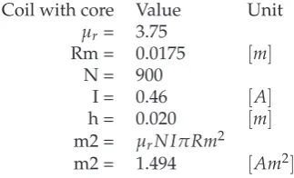
Coil with core Value Unit
μr= 1.00
Rm = 0.0175 [m]
N = 900
I = 0.46 [A]
h = 0.020 [m]
m2 = μrN IπRm2
m2 = 0.398 [Am2]
46 Electromagnetism Framework
Table 7.5: fefor a coreless electromagnet based onm1andm2.
fe Value Unit
μ0= 1.26E-06 [H / m]
m1 = 0.683 [Am2]
m2 = 0.398 [Am2]
h m1 = 0.010 [m]
h m2 = 0.020 [m]
h gap = 0.024 [m]
z1 = 0.039 [m]
fe= 3μ0m1m2/(4piz1144)
fe= 0.035 [N]
Figure 7.6: Schematic of electromagnet without core interacting with ring magnet.
magnet interaction. The core in an electromagnet alters the electromagnetic flux in such a way that it closer corresponds to a permanent magnet. Hence, without the core the results will get worse.
7.2.3
Electromagnet - Core
We have seen that our model performs quite poorly on a coreless electromagnet. For this reason we add a core, this is common practice and nearly all electromagnets do have a core. We will show that by adding a core to our electromagnet the predictions of our theoretical framework will increase in accuracy. It will also largely increase the perceived strength, since the magnetic flux will get more focused by the core.
![Figure 1.2: Example of an exoskeleton for rehabilitation [15].](https://thumb-us.123doks.com/thumbv2/123dok_us/9694423.470750/10.595.177.390.196.485/figure-example-of-an-exoskeleton-for-rehabilitation.webp)
![Figure 2.1: Example of different stages in learning in an experimental setting [2].](https://thumb-us.123doks.com/thumbv2/123dok_us/9694423.470750/18.595.71.494.242.482/figure-example-different-stages-learning-experimental-setting.webp)
![Figure 3.3: Ubi-Pen by Kyung et al. [27].](https://thumb-us.123doks.com/thumbv2/123dok_us/9694423.470750/25.595.103.523.248.459/figure-ubi-pen-by-kyung-et-al.webp)
![Figure 3.4: Mechanical overview of Iwata [20] their proposal.](https://thumb-us.123doks.com/thumbv2/123dok_us/9694423.470750/26.595.183.377.184.439/figure-mechanical-overview-iwata-proposal.webp)

![Figure 8.5: Schematic of the mpcc output as well as internal variables [29].](https://thumb-us.123doks.com/thumbv2/123dok_us/9694423.470750/63.595.122.495.137.362/figure-schematic-mpcc-output-internal-variables.webp)